WebGPU学习(九):学习“fractalCube”示例
大家好,本文学习Chrome->webgpu-samplers->fractalCube示例。
上一篇博文:
WebGPU学习(八):学习“texturedCube”示例
下一篇博文:
WebGPU学习(十):介绍“GPU实现粒子效果”
学习fractalCube.ts
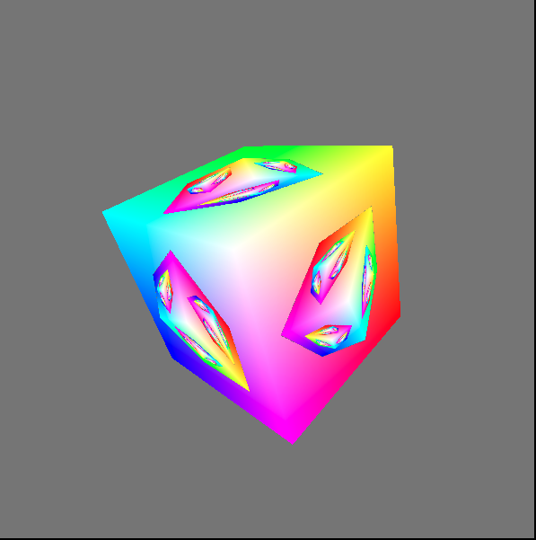
最终渲染结果:
该示例展示了如何用上一帧渲染的结果作为下一帧的纹理。
与“texturedCube”示例相比,该示例的纹理并不是来自图片,而是来自上一帧渲染的结果
下面,我们打开fractalCube.ts文件,分析相关代码:
传输顶点的color
它与“texturedCube”示例->“传递顶点的uv数据”类似,这里不再分析
上一帧渲染的结果作为下一帧的纹理
- 配置swapChain
因为swapChain保存了上一帧渲染的结果,所以将其作为下一帧纹理的source。因此它的usage需要增加GPUTextureUsage.COPY_SRC:
  const swapChain = context.configureSwapChain({
    device,
    format: "bgra8unorm",
    usage: GPUTextureUsage.OUTPUT_ATTACHMENT | GPUTextureUsage.COPY_SRC,
  });
- 创建空纹理(cubeTexture)和sampler,设置到uniform bind group中
相关代码如下:
  const fragmentShaderGLSL = `#version 450
  ...
  layout(set = 0, binding = 2) uniform texture2D myTexture;
  ...

  void main() {
    vec4 texColor = texture(sampler2D(myTexture, mySampler), fragUV * 0.8 + 0.1);

    ...

    outColor = mix(texColor, fragColor, f);
  }`;

  ...

  const cubeTexture = device.createTexture({
    size: { width: canvas.width, height: canvas.height, depth: 1 },
    format: "bgra8unorm",
    usage: GPUTextureUsage.COPY_DST | GPUTextureUsage.SAMPLED,
  });

  const sampler = device.createSampler({
    magFilter: "linear",
    minFilter: "linear",
  });

  const uniformBindGroup = device.createBindGroup({
    layout: bindGroupLayout,
    bindings: [
    ...
    {
      binding: 1,
      resource: sampler,
    }, {
      binding: 2,
      //传递cubeTexture到fragment shader中
      resource: cubeTexture.createView(),
    }],
  });
- 绘制和拷贝
在每一帧中:
绘制带纹理的立方体;
将渲染结果(swapChainTexture)拷贝到cubeTexture中。
相关代码如下:
  return function frame() {
    const swapChainTexture = swapChain.getCurrentTexture();

    renderPassDescriptor.colorAttachments[0].attachment = swapChainTexture.createView();

    const commandEncoder = device.createCommandEncoder({});
    const passEncoder = commandEncoder.beginRenderPass(renderPassDescriptor);
    ...
    passEncoder.setBindGroup(0, uniformBindGroup);
    ...
    passEncoder.draw(36, 1, 0, 0);
    passEncoder.endPass();

    commandEncoder.copyTextureToTexture({
      texture: swapChainTexture,
    }, {
      texture: cubeTexture,
    }, {
      width: canvas.width,
      height: canvas.height,
      depth: 1,
    });

    device.defaultQueue.submit([commandEncoder.finish()]);

    ...

  }
分析shader代码
本示例的vertex shader与“texturedCube”示例的vertex shader相比,增加了color attribute:
  const vertexShaderGLSL = `#version 450
  ...
  layout(location = 1) in vec4 color;
  ...

  layout(location = 0) out vec4 fragColor;
  ...

  void main() {
    ...
    fragColor = color;
    ...
  }`;
fragment shader的代码如下:
  const fragmentShaderGLSL = `#version 450
  layout(set = 0, binding = 1) uniform sampler mySampler;
  layout(set = 0, binding = 2) uniform texture2D myTexture;

  layout(location = 0) in vec4 fragColor;
  layout(location = 1) in vec2 fragUV;
  layout(location = 0) out vec4 outColor;

  void main() {
    vec4 texColor = texture(sampler2D(myTexture, mySampler), fragUV * 0.8 + 0.1);

    // 1.0 if we're sampling the background
    float f = float(length(texColor.rgb - vec3(0.5, 0.5, 0.5)) < 0.01);

    outColor = mix(texColor, fragColor, f);
  }`;
第10行对fragUV进行了处理,我们会在分析渲染时间线中分析它。
第13行和第15行相当于做了if判断:
if(纹理颜色 === 背景色){
    outColor = fragColor
}
else{
    outColor = 纹理颜色
}
这里之所以不用if判断而使用计算的方式,是为了减少条件判断,提高gpu的并行性
分析渲染时间线
下面分析下渲染的时间线:
第一帧
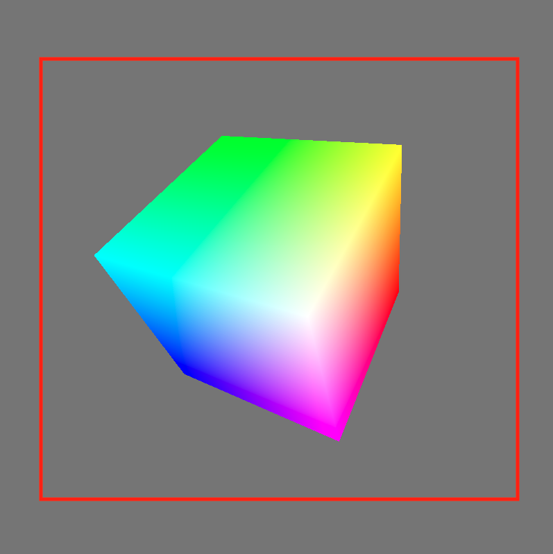
因为纹理为空纹理,它的颜色为背景色,所以fragment shader的outColor始终为fragColor,因此立方体的所有片段的颜色均为fragColor。
第一帧的渲染结果如下:

第一帧绘制结束后,渲染结果会被拷贝到cubeTexture中。
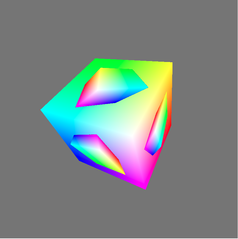
第二帧
分析执行的fragment shader代码:
  const fragmentShaderGLSL = `#version 450
  layout(set = 0, binding = 1) uniform sampler mySampler;
  layout(set = 0, binding = 2) uniform texture2D myTexture;

  layout(location = 0) in vec4 fragColor;
  layout(location = 1) in vec2 fragUV;
  layout(location = 0) out vec4 outColor;

  void main() {
    vec4 texColor = texture(sampler2D(myTexture, mySampler), fragUV * 0.8 + 0.1);

    // 1.0 if we're sampling the background
    float f = float(length(texColor.rgb - vec3(0.5, 0.5, 0.5)) < 0.01);

    outColor = mix(texColor, fragColor, f);
  }`;
- 第10行的“fragUV * 0.8 + 0.1”是为了取纹理坐标u、v方向的[0.1-0.9]部分,从而使纹理中立方体所占比例更大。
得到的纹理区域如下图的红色区域所示:
- 第13行和第15行代码,将纹理中的背景色替换为了fragColor
第二帧的渲染结果如下:
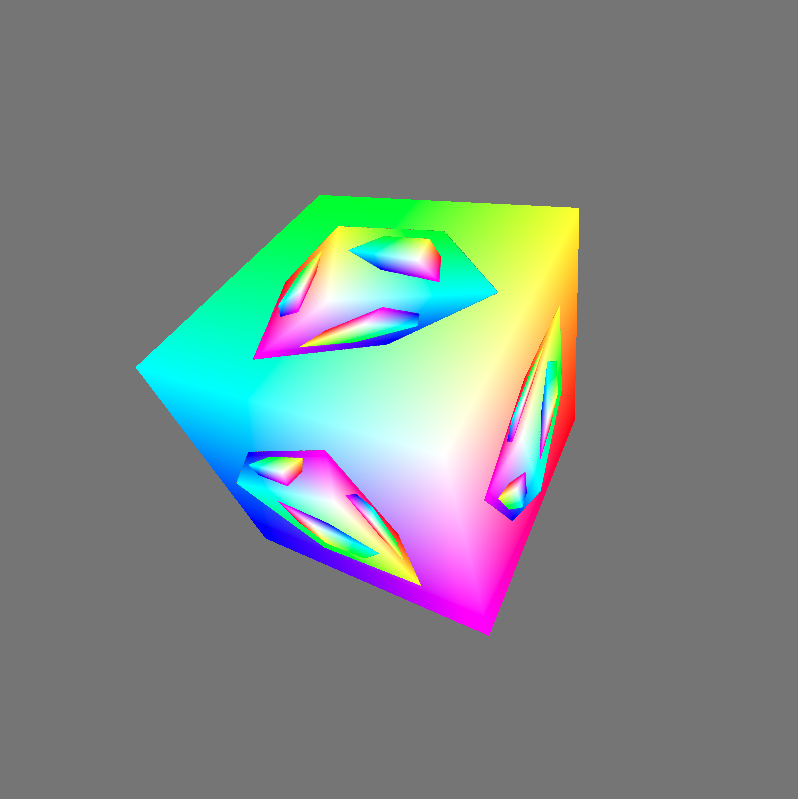
- 第三帧
依次类推,第三帧的渲染结果如下:
参考资料
感谢您的阅读~
扫码加入我的QQ群:

扫码加入免费知识星球-YYC的Web3D旅程:


 浙公网安备 33010602011771号