一种同时实现多次采样并减少CPU中断触发次数的方法
背景:我要实现多路AD采样,采样点数多的同时采样次数也需要很多,如果每个AD对应的DMA在传输完成后都触发一次中断,那对于CPU的负荷会比较大,由于需求特殊,故寻找一种能够实现一次总采样只触发一次中断的方法。这个紧跟上一篇随笔,这里引一下:https://www.cnblogs.com/daydaygood/p/18811676
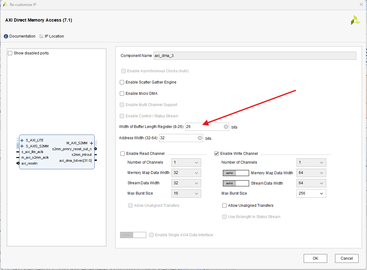
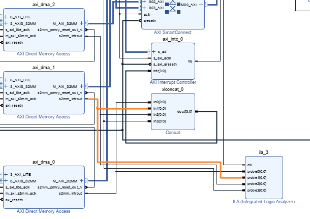
先更改一些IP核的设置,首先,调整DMA核的最大传输字节数,其次把INTC控制器的输入触发全部改成边沿上升沿触发(虽然DMA中断输出是电平触发,但这不影响,我之前没有改,遇到了一些问题,但我改了之后就可以这样做了),输出触发也改为上升沿触发,这里增加一个ila_3来查看每个dma中断输出情况。

重点来了,我们更改一下data_generate的代码,重点是这两部分,首先我们让tlast只在最后一次采样的最后一个数据拉高,其次我们让状态机在多次采样的过程中稳定运行,完整代码在后面,简单来讲,我分四次来传输16384个从1到16384的数据,分四次传输来模拟多次采样。


点击查看代码
`timescale 1ns / 1ps
//////////////////////////////////////////////////////////////////////////////////
// Company:
// Engineer:
//
// Create Date: 2025/04/04 18:45:06
// Design Name:
// Module Name: data_generate
// Project Name:
// Target Devices:
// Tool Versions:
// Description:
//
// Dependencies:
//
// Revision:
// Revision 0.01 - File Created
// Additional Comments:
//
//////////////////////////////////////////////////////////////////////////////////


`timescale 1 ns / 1 ps

	module data_generate #(
		// Users to add parameters here

		// User parameters ends
		// Do not modify the parameters beyond this line

		// Width of S_AXIS address bus. The slave accepts the read and write addresses of width C_M_AXIS_TDATA_WIDTH.
		parameter integer C_M_AXIS_TDATA_WIDTH	= 64,
		// Start count is the number of clock cycles the master will wait before initiating/issuing any transaction.
		parameter integer C_M_START_COUNT	= 32
	)
	(
		// Users to add ports here
        input wire  GPIO_start_flag,
		// User ports ends
		// Do not modify the ports beyond this line

		// Global ports
		input wire  M_AXIS_ACLK,
		//
		input wire  M_AXIS_ARESETN,
		// Master Stream Ports. TVALID indicates that the master is driving a valid transfer, A transfer takes place when both TVALID and TREADY are asserted.
		output wire  M_AXIS_TVALID,
		// TDATA is the primary payload that is used to provide the data that is passing across the interface from the master.
		output wire [C_M_AXIS_TDATA_WIDTH-1 : 0] M_AXIS_TDATA,
		// TSTRB is the byte qualifier that indicates whether the content of the associated byte of TDATA is processed as a data byte or a position byte.
		output wire [(C_M_AXIS_TDATA_WIDTH/8)-1 : 0] M_AXIS_TSTRB,
		// TLAST indicates the boundary of a packet.
		output wire  M_AXIS_TLAST,
		// TREADY indicates that the slave can accept a transfer in the current cycle.
		input wire  M_AXIS_TREADY
	);
	// Total number of output data
	localparam NUMBER_OF_OUTPUT_WORDS = 16384;

	// function called clogb2 that returns an integer which has the
	// value of the ceiling of the log base 2.
	function integer clogb2 (input integer bit_depth);
	  begin
	    for(clogb2=0; bit_depth>0; clogb2=clogb2+1)
	      bit_depth = bit_depth >> 1;
	  end
	endfunction

	// WAIT_COUNT_BITS is the width of the wait counter.
	localparam integer WAIT_COUNT_BITS = clogb2(C_M_START_COUNT-1);

	// bit_num gives the minimum number of bits needed to address 'depth' size of FIFO.
	localparam bit_num  = clogb2(NUMBER_OF_OUTPUT_WORDS);

	// Define the states of state machine
	// The control state machine oversees the writing of input streaming data to the FIFO,
	// and outputs the streaming data from the FIFO
	localparam [1:0] IDLE = 2'b00,        // This is the initial/idle state

	                INIT_COUNTER  = 2'b01, // This state initializes the counter, once
	                                // the counter reaches C_M_START_COUNT count,
	                                // the state machine changes state to SEND_STREAM
	                SEND_STREAM   = 2'b10; // In this state the
	                                     // stream data is output through M_AXIS_TDATA
	// State variable
	reg [1:0] mst_exec_state;
	// Example design FIFO read pointer
	reg [bit_num-1:0] read_pointer;
	reg [bit_num-1:0] read_pointer_single;
	// AXI Stream internal signals
	//wait counter. The master waits for the user defined number of clock cycles before initiating a transfer.
	reg [WAIT_COUNT_BITS-1 : 0] 	count;
	//streaming data valid
	wire  	axis_tvalid;
	//streaming data valid delayed by one clock cycle
	reg  	axis_tvalid_delay;
	//Last of the streaming data
	wire  	axis_tlast;
	//Last of the streaming data delayed by one clock cycle
	reg  	axis_tlast_delay;
	//FIFO implementation signals
	reg [C_M_AXIS_TDATA_WIDTH-1 : 0] 	stream_data_out;
	wire  	tx_en;
	//The master has issued all the streaming data stored in FIFO
	reg  	tx_done;


	// I/O Connections assignments

	assign M_AXIS_TVALID	= axis_tvalid_delay;
	assign M_AXIS_TDATA	= stream_data_out;
	assign M_AXIS_TLAST	= axis_tlast_delay;
	assign M_AXIS_TSTRB	= {(C_M_AXIS_TDATA_WIDTH/8){1'b1}};


	// Control state machine implementation
	always @(posedge M_AXIS_ACLK)
	begin
	  if (!M_AXIS_ARESETN)
	  // Synchronous reset (active low)
	    begin
	      mst_exec_state <= IDLE;
	      count    <= 0;
	    end
	  else
	    case (mst_exec_state)
	      IDLE:
	        // The slave starts accepting tdata when
	        // there tvalid is asserted to mark the
	        // presence of valid streaming data
	        //if ( count == 0 )
	        begin
	            mst_exec_state  <= INIT_COUNTER;
                count    <= 0;
	        end
	        //else
	        //  begin
	        //    mst_exec_state  <= IDLE;
	        //  end

	      INIT_COUNTER:
	        // The slave starts accepting tdata when
	        // there tvalid is asserted to mark the
	        // presence of valid streaming data
	        if ( count == C_M_START_COUNT - 1 )
	          begin
	            mst_exec_state  <= SEND_STREAM;
	          end
	        else
	          begin
	            count <= count + 1;
	            mst_exec_state  <= INIT_COUNTER;
	          end

	      SEND_STREAM:
	        // The example design streaming master functionality starts
	        // when the master drives output tdata from the FIFO and the slave
	        // has finished storing the S_AXIS_TDATA
	        if (tx_done)
	          begin
	            mst_exec_state <= IDLE;
	          end
	        else
	          begin
	            mst_exec_state <= SEND_STREAM;
	          end
	    endcase
	end

reg     GPIO_start_flag_delay;
wire    start_flag;

assign start_flag = ((GPIO_start_flag)&&(!GPIO_start_flag_delay));

always @(posedge M_AXIS_ACLK) begin
    if (!M_AXIS_ARESETN) begin
        GPIO_start_flag_delay <= 1'd0;
    end else begin
        GPIO_start_flag_delay <= GPIO_start_flag;
    end
end

reg wr_en;

always @(posedge M_AXIS_ACLK) begin
    if (!M_AXIS_ARESETN) begin
        wr_en <= 1'd0;
    end else    if (start_flag) begin
        wr_en <= 1'd1;
    end else    if (tx_done) begin
        wr_en <= 1'd0;
    end
end

	//tvalid generation
	//axis_tvalid is asserted when the control state machine's state is SEND_STREAM and
	//number of output streaming data is less than the NUMBER_OF_OUTPUT_WORDS.
	assign axis_tvalid = ((wr_en)&&(mst_exec_state == SEND_STREAM) && (read_pointer_single < 4096));

	// AXI tlast generation
	// axis_tlast is asserted number of output streaming data is NUMBER_OF_OUTPUT_WORDS-1
	// (0 to NUMBER_OF_OUTPUT_WORDS-1)
	assign axis_tlast = ((read_pointer == NUMBER_OF_OUTPUT_WORDS-1)&&(tx_en));


	// Delay the axis_tvalid and axis_tlast signal by one clock cycle
	// to match the latency of M_AXIS_TDATA
	always @(posedge M_AXIS_ACLK)
	begin
	  if (!M_AXIS_ARESETN)
	    begin
	      axis_tvalid_delay <= 1'b0;
	      axis_tlast_delay <= 1'b0;
	    end
	  else
	    begin
	      axis_tvalid_delay <= axis_tvalid;
	      axis_tlast_delay <= axis_tlast;
	    end
	end
	//read_pointer pointer

always@(posedge M_AXIS_ACLK)   begin
	    if(!M_AXIS_ARESETN)   begin
	      read_pointer  <= 0;
		  read_pointer_single	<= 0;
	      tx_done       <= 1'b0;
	    end else  case (mst_exec_state)
        SEND_STREAM :begin
			if (tx_en) begin
            	if (read_pointer < NUMBER_OF_OUTPUT_WORDS-1)   begin
					read_pointer <= read_pointer + 1;
					if (read_pointer_single == 4095) begin
						read_pointer_single = 0;
						tx_done 	 	<= 1'b1;
					end	else	begin
						read_pointer_single <= read_pointer_single + 1;
						tx_done 	 	<= 1'b0;
					end
            	end else    begin
					read_pointer    		<= 0;
					read_pointer_single     <= 0;
              		tx_done 	 			<= 1'b1;
            	end
        	end
		end
        default: begin
            read_pointer    		<= read_pointer;
			read_pointer_single    	<= 0;
            tx_done         		<= 1'b0;
        end
      endcase
end

	//FIFO read enable generation

	assign tx_en = M_AXIS_TREADY && axis_tvalid;

	    // Streaming output data is read from FIFO
	    always @( posedge M_AXIS_ACLK )
	    begin
	      if(!M_AXIS_ARESETN)
	        begin
	          stream_data_out <= 1;
	        end
	      else if (tx_en)// && M_AXIS_TSTRB[byte_index]
	        begin
	          stream_data_out <= read_pointer + 32'b1;
	        end
	    end

	// Add user logic here

	// User logic ends

	endmodule
编译后我们去vitis里,编写main程序,代码如下,其实就是,让data_generate分时产生四次数据,同时记录中断情况,来查看该方案是否可行。
点击查看代码
#include "my_init.h"
#include "my_intr.h"
#include "my_code.h"
#include "globals.h"

int main( ){

    Xil_ICacheEnable();
    Xil_DCacheEnable();
    xil_printf("\r\n--- Entering main() --- \r\n");

// 1.4个DMA以及GPIO初始化
    dma_init_for_four_adc_dma(&axi_dma_0, &axi_dma_1, &axi_dma_2, &axi_dma_3,&dma_channels[0], &dma_channels[1],&dma_channels[2],&dma_channels[3]);
    GPIO_init(&Gpio);
// 2.初始化 XScuGIC、Interrupt_Controller、注册异常以及建立中断系统
    my_setup_XScuGic_init(&intc);
    my_Interrupt_Controller_init(&InterruptController, &intrcontext[0], &intrcontext[1], &intrcontext[2], &intrcontext[3],
                                        &dma_channels[0], &dma_channels[1], &dma_channels[2], &dma_channels[3]);
    my_Exception_start();
    setup_interrupts(&intc, &InterruptController);
// 3.开启其他中断
    platform_enable_interrupts(&intc, &InterruptController, &dma_channels[0], &dma_channels[1], &dma_channels[2], &dma_channels[3]);
    dma_receive_for_four_adc_data();
    for (int i = 0; i < 4; i++)
    {
        sleep(1);
        xil_printf("\r\n--- %d --- \r\n",i);
        XGpio_DiscreteWrite(&Gpio, 1, 0x1);
        sleep(1);
        XGpio_DiscreteWrite(&Gpio, 1, 0x0);
    }
    dma_receive_for_four_adc_data();
    for (int i = 0; i < 4; i++)
    {
        sleep(1);
        xil_printf("\r\n--- %d --- \r\n",i);
        XGpio_DiscreteWrite(&Gpio, 1, 0x1);
        sleep(1);
        XGpio_DiscreteWrite(&Gpio, 1, 0x0);
    }
    dma_receive_for_four_adc_data();
    for (int i = 0; i < 4; i++)
    {
        sleep(1);
        xil_printf("\r\n--- %d --- \r\n",i);
        XGpio_DiscreteWrite(&Gpio, 1, 0x1);
        sleep(1);
        XGpio_DiscreteWrite(&Gpio, 1, 0x0);
    }
//开始循环
    return XST_SUCCESS;
}
串口打印信息情况。

数据传输情况。

ila观察到的中断情况。

那这个方法呢,其实只是减少了中断触发次数,在DMA总线中可能会产生抢占行为,如下图,单路传输的时候,总线上就一个dma,多路dma的时候,就会微观上分时传输,这并不是很好,具体还要看实际情况。


 浙公网安备 33010602011771号