

使用多路DMA进行数据传输
DMA的设置

FIFO的设置,第二页默认

这里特别注意,fifo的复位一定要来自DMA的复位out,这个示例里使用全局复位影响不大,但其他有些情况下会带来问题
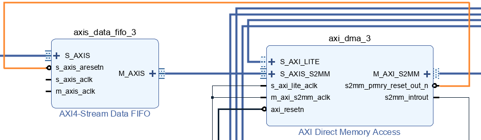
DMA读时钟100MHz
FIFO写时钟250MHz,模拟高速ADC数据产生

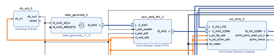
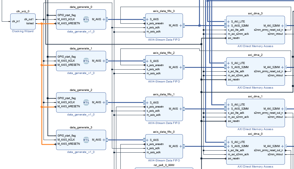
同样的的情况,模拟四路数据传输,模拟多通道情况。MMCM IP核的locked作为generate rtl数据产生模块的复位信号
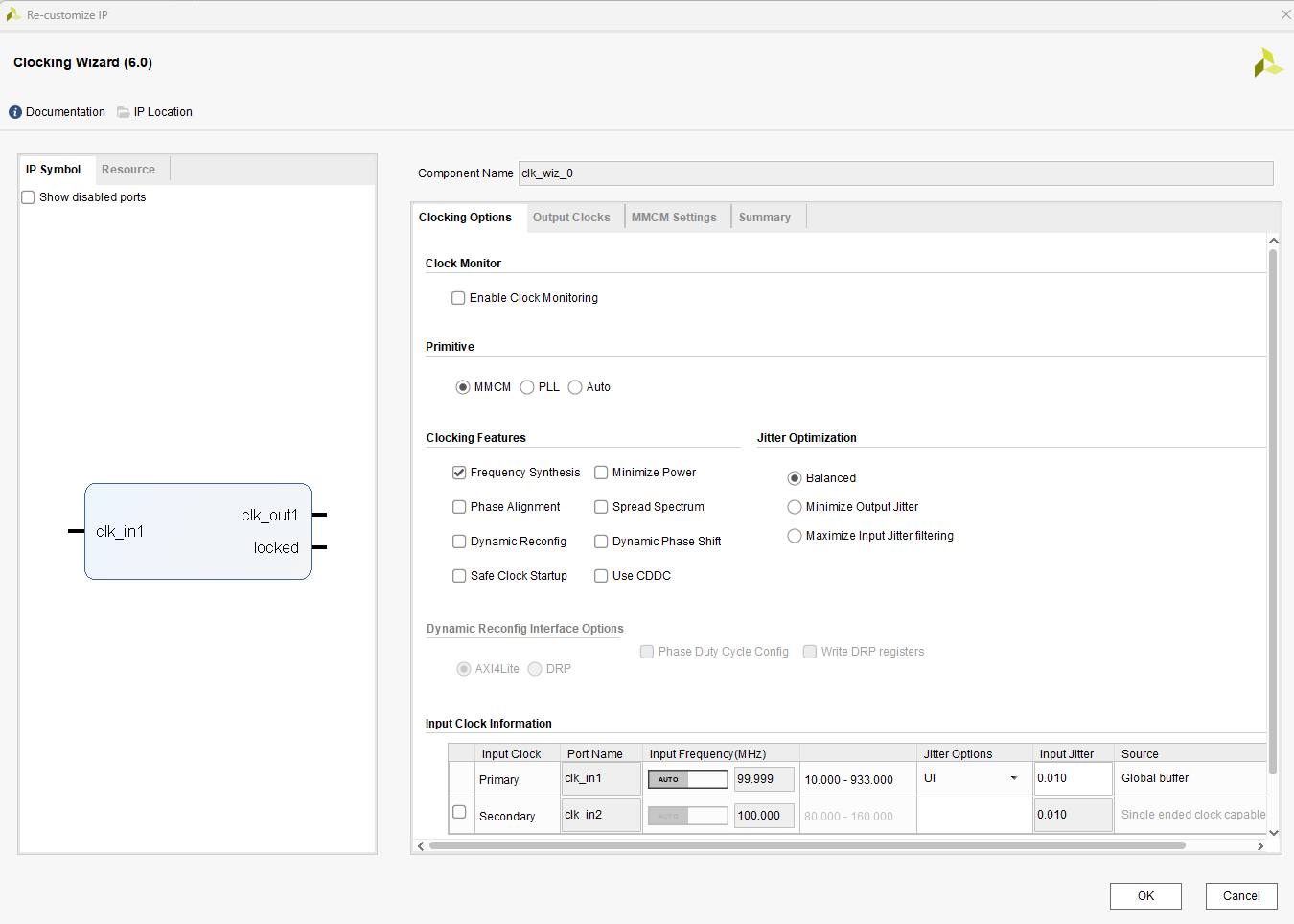
MMCM设置,输入100Mhz,输出250MHz。未展示部分默认


使用xlconcat和intc形成多级中断

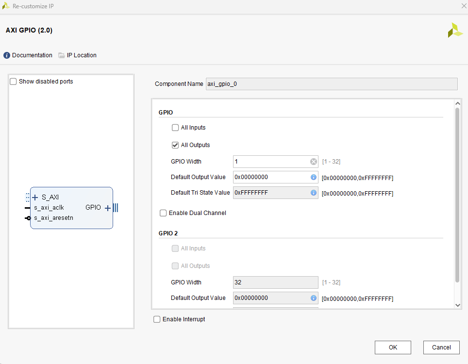
使用AXI GPIO产生开始信号,data_generate模块里对开始信号做处理,以便形成完整的数据传输

点击查看代码
reg     GPIO_start_flag_delay;
wire    start_flag;

assign start_flag = ((GPIO_start_flag)&&(!GPIO_start_flag_delay));

always @(posedge M_AXIS_ACLK) begin
    if (!M_AXIS_ARESETN) begin
        GPIO_start_flag_delay <= 1'd0;
    end else begin
        GPIO_start_flag_delay <= GPIO_start_flag;
    end
end

reg wr_en;

always @(posedge M_AXIS_ACLK) begin
    if (!M_AXIS_ARESETN) begin
        wr_en <= 1'd0;
    end else    if (start_flag) begin
        wr_en <= 1'd1;
    end else    if (tx_done) begin
        wr_en <= 1'd0;
    end
end

	//tvalid generation
	//axis_tvalid is asserted when the control state machine's state is SEND_STREAM and
	//number of output streaming data is less than the NUMBER_OF_OUTPUT_WORDS.
	assign axis_tvalid = ((wr_en)&&(mst_exec_state == SEND_STREAM) && (read_pointer < NUMBER_OF_OUTPUT_WORDS));

	// AXI tlast generation
	// axis_tlast is asserted number of output streaming data is NUMBER_OF_OUTPUT_WORDS-1
	// (0 to NUMBER_OF_OUTPUT_WORDS-1)
	assign axis_tlast = ((read_pointer == NUMBER_OF_OUTPUT_WORDS-1)&&(tx_en));
0号ila用来观察PS对dma的axi-lite通信

1号ila用来观察DMA对fifo的读取情况
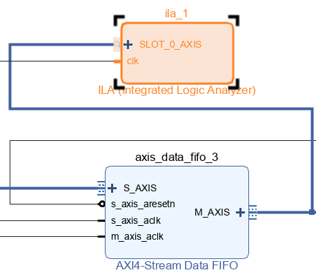
2号ila用来观察DMA对数据的传输情况

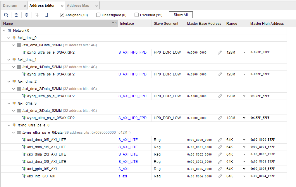
最后是地址分配
综合,实现,生成bit流,导出硬件文件,进入vitis
创建工程后,进入bsp,如下所示,dma驱动 intc驱动,gpio驱动都在

编写代码后(代码在最后面),进入调试界面,下面是某一次dma接收之后的情况,18007FF0这个地址这行是上一次接收的末尾,红色这次接收的开始,正好是1-0x1000,共计4096个数,main函数里运行了三次传输,均为正确,第四次是错误传输的示例,表明开始信号是上升沿

DMA传输错误情况下不会产生DMA中断

下面是PL端ila的信号,感兴趣的可以自己设置触发条件查看通信情况,这里不再细说,毕竟功能上已经实现了。


最后是vitis的代码
点击查看代码
globals.h
#ifndef GLOBALS_H
#define GLOBALS_H

#include "xparameters.h"
#include "xil_printf.h"
#include "xil_cache.h"
#include "xaxidma.h"
#include "xgpio.h"
#include "xscugic.h"
#include "xintc.h"
#include "xil_io.h"

#define DDR_BASE_ADDR XPAR_PSU_DDR_0_S_AXI_BASEADDR //0x00000000    DDR基地址
#define AXI_DMA_0_ADDR  DDR_BASE_ADDR               //0x0000_0000-0x07FF_FFFF
#define AXI_DMA_1_ADDR (DDR_BASE_ADDR + 0x08000000) //0x0800_0000-0x0FFF_FFFF
#define AXI_DMA_2_ADDR (DDR_BASE_ADDR + 0x10000000) //0x1000_0000-0x17FF_FFFF
#define AXI_DMA_3_ADDR (DDR_BASE_ADDR + 0x18000000) //0x1800_0000-0x1FFF_FFFF

#define ONE_PKT_LENGTH  0x8000  //单次接收包长度

#define NUMBER_RECEIVE  0x1000  //总接收次数

typedef struct {
    u8  DMA_ID;
    XAxiDma *dma_inst;
    u8 *base_addr;
    u8 *current_addr;
    u16 transfer_count;
    u32 len;
    volatile int transfer_end_flag;
    unsigned int rx_intr_ID;
} DmaChannel;

DmaChannel dma_channels[4];

typedef struct {
    XIntc *intc;      // INTC控制器实例
    DmaChannel *dma_channels;     // DMA实例
} IntrContext;

IntrContext intrcontext[4];

// 全局变量
XAxiDma axi_dma_0;                         //AXI_DMA_0 实例
XAxiDma axi_dma_1;                         //AXI_DMA_1 实例
XAxiDma axi_dma_2;                         //AXI_DMA_2 实例
XAxiDma axi_dma_3;                         //AXI_DMA_3 实例

XGpio Gpio;

XScuGic intc;                              // 中断控制器
XIntc InterruptController;                 //* Instance of the Interrupt Controller */

int status;

// 状态标志
volatile int dma_transfer_start_flag;       // DMA传输启动标志

#endif // GLOBALS_H
点击查看代码
my_init.h
#ifndef MY_INIT_H
#define MY_INIT_H

#include "globals.h"

#define DMA_0_DEV_ID            XPAR_AXIDMA_0_DEVICE_ID     //AXI_DMA_0-4的器件 ID
#define DMA_1_DEV_ID            XPAR_AXIDMA_1_DEVICE_ID
#define DMA_2_DEV_ID            XPAR_AXIDMA_2_DEVICE_ID
#define DMA_3_DEV_ID            XPAR_AXIDMA_3_DEVICE_ID

#define GPIO_EXAMPLE_DEVICE_ID  XPAR_GPIO_0_DEVICE_ID

#define DMA_0_RX_INTR_ID        XPAR_INTC_0_AXIDMA_0_VEC_ID
#define DMA_1_RX_INTR_ID        XPAR_INTC_0_AXIDMA_1_VEC_ID
#define DMA_2_RX_INTR_ID        XPAR_INTC_0_AXIDMA_2_VEC_ID
#define DMA_3_RX_INTR_ID        XPAR_INTC_0_AXIDMA_3_VEC_ID

/************************** Function Prototypes ******************************/
int	dma_init_for_four_adc_dma(XAxiDma *axi_dma_0, XAxiDma *axi_dma_1, XAxiDma *axi_dma_2, XAxiDma *axi_dma_3,
    DmaChannel *dma_channels_0,  DmaChannel *dma_channels_1,  DmaChannel *dma_channels_2,  DmaChannel *dma_channels_3);
int GPIO_init(XGpio *Gpio);
#endif // MY_INIT_H
点击查看代码
my_init.c
#include "my_init.h"
int	dma_init_for_four_adc_dma(XAxiDma *axi_dma_0, XAxiDma *axi_dma_1, XAxiDma *axi_dma_2, XAxiDma *axi_dma_3,
     DmaChannel *dma_channels_0,  DmaChannel *dma_channels_1,  DmaChannel *dma_channels_2,  DmaChannel *dma_channels_3);
	static int dma_init(XAxiDma *axi_dma, u32 DMA_DEV_ID) ;

int	dma_init_for_four_adc_dma(XAxiDma *axi_dma_0, XAxiDma *axi_dma_1, XAxiDma *axi_dma_2, XAxiDma *axi_dma_3,
    DmaChannel *dma_channels_0,  DmaChannel *dma_channels_1,  DmaChannel *dma_channels_2,  DmaChannel *dma_channels_3){
	// DMA初始化
	dma_init(axi_dma_0, DMA_0_DEV_ID);
	dma_init(axi_dma_1, DMA_1_DEV_ID);
	dma_init(axi_dma_2, DMA_2_DEV_ID);
	dma_init(axi_dma_3, DMA_3_DEV_ID);
    *dma_channels_0 = (DmaChannel){0, axi_dma_0, (u8 *)AXI_DMA_0_ADDR, (u8 *)AXI_DMA_0_ADDR, 0, ONE_PKT_LENGTH, 0, DMA_0_RX_INTR_ID};
	*dma_channels_1 = (DmaChannel){1, axi_dma_1, (u8 *)AXI_DMA_1_ADDR, (u8 *)AXI_DMA_1_ADDR, 0, ONE_PKT_LENGTH, 0, DMA_1_RX_INTR_ID};
	*dma_channels_2 = (DmaChannel){2, axi_dma_2, (u8 *)AXI_DMA_2_ADDR, (u8 *)AXI_DMA_2_ADDR, 0, ONE_PKT_LENGTH, 0, DMA_2_RX_INTR_ID};
	*dma_channels_3 = (DmaChannel){3, axi_dma_3, (u8 *)AXI_DMA_3_ADDR, (u8 *)AXI_DMA_3_ADDR, 0, ONE_PKT_LENGTH, 0, DMA_3_RX_INTR_ID};

    return XST_SUCCESS;
}

static int dma_init(XAxiDma *axi_dma, u32 DMA_DEV_ID) {
    static XAxiDma_Config *config;
    config = XAxiDma_LookupConfig(DMA_DEV_ID);
    if (!config) {
        xil_printf("No config found for %d\r\n", DMA_DEV_ID);
        return XST_FAILURE;
    }
    status = XAxiDma_CfgInitialize(axi_dma, config);
    if (status != XST_SUCCESS) {
        xil_printf("Initialization failed %d\r\n", status);
        return XST_FAILURE;
    }
    if (XAxiDma_HasSg(axi_dma)) {
        xil_printf("Device configured as SG mode\r\n");
        return XST_FAILURE;
    }
    return XST_SUCCESS;
}


int GPIO_init(XGpio *Gpio){
    	/* Initialize the GPIO driver */
    int Status;
	Status = XGpio_Initialize(Gpio, GPIO_EXAMPLE_DEVICE_ID);
	if (Status != XST_SUCCESS) {
		xil_printf("Gpio Initialization Failed\r\n");
		return XST_FAILURE;
	}
	XGpio_SetDataDirection(Gpio, 1, 0);
    return XST_SUCCESS;
}
点击查看代码
my_intr.h
#ifndef MY_INTR_H
#define MY_INTR_H

#include "globals.h"

#define INTC_DEVICE_ID		        XPAR_SCUGIC_SINGLE_DEVICE_ID    //SCUGIC的器件 ID

#define INTC_Controller_DEVICE_ID   XPAR_INTC_0_DEVICE_ID           //INTC Controller的设备ID
#define INTC_Controller_INTR_ID     XPAR_FABRIC_INTC_0_VEC_ID

#define RESET_TIMEOUT_COUNTER 10000 //复位时间

#define INTR_PRIORITY     0xA0
#define TRIGGER_TYPE      0x3


/************************** Function Prototypes ******************************/
int my_setup_XScuGic_init(XScuGic *xscugic_inst);
int	my_Interrupt_Controller_init(XIntc *Interrupt_Controller, IntrContext *intrcontext_0, IntrContext *intrcontext_1, IntrContext *intrcontext_2, IntrContext *intrcontext_3,
    DmaChannel *dma_channels_0,  DmaChannel *dma_channels_1,  DmaChannel *dma_channels_2,  DmaChannel *dma_channels_3);
int	my_Exception_start(void);
int setup_interrupts(XScuGic *intc, XIntc *InterruptController);
int platform_enable_interrupts(XScuGic *intc, XIntc *InterruptController, DmaChannel *dma_channels_0,  DmaChannel *dma_channels_1,  DmaChannel *dma_channels_2,  DmaChannel *dma_channels_3);
int platform_disable_interrupts(XIntc *InterruptController, DmaChannel *dma_channels_0,  DmaChannel *dma_channels_1,  DmaChannel *dma_channels_2,  DmaChannel *dma_channels_3);


#endif // MY_INTR_H
点击查看代码
my_intr.c
#include "my_intr.h"
int my_setup_XScuGic_init(XScuGic *xscugic_inst);
int	my_Interrupt_Controller_init(XIntc *Interrupt_Controller, IntrContext *intrcontext_0, IntrContext *intrcontext_1, IntrContext *intrcontext_2, IntrContext *intrcontext_3,
    DmaChannel *dma_channels_0,  DmaChannel *dma_channels_1,  DmaChannel *dma_channels_2,  DmaChannel *dma_channels_3);
int	my_Exception_start(void);
int setup_interrupts(XScuGic *intc, XIntc *InterruptController);
    static void dma_rx_intr_handler(void *callback);
        static void handle_dma_error(XAxiDma *axi_dma);
int platform_enable_interrupts(XScuGic *intc, XIntc *InterruptController, DmaChannel *dma_channels_0,  DmaChannel *dma_channels_1,  DmaChannel *dma_channels_2,  DmaChannel *dma_channels_3);
int platform_disable_interrupts(XIntc *InterruptController, DmaChannel *dma_channels_0,  DmaChannel *dma_channels_1,  DmaChannel *dma_channels_2,  DmaChannel *dma_channels_3);

int my_setup_XScuGic_init(XScuGic *xscugic_inst){
    static XScuGic_Config *IntcConfig;
    IntcConfig = XScuGic_LookupConfig(INTC_DEVICE_ID);
    status = XScuGic_CfgInitialize(xscugic_inst, IntcConfig, IntcConfig -> CpuBaseAddress);
	if (status != XST_SUCCESS) {
        xil_printf("XScuGic_init failed %d\r\n", status);
        return XST_FAILURE;
    }
	return XST_SUCCESS;
}

int	my_Interrupt_Controller_init(XIntc *Interrupt_Controller, IntrContext *intrcontext_0, IntrContext *intrcontext_1, IntrContext *intrcontext_2, IntrContext *intrcontext_3,
                     DmaChannel *dma_channels_0,  DmaChannel *dma_channels_1,  DmaChannel *dma_channels_2,  DmaChannel *dma_channels_3){
	status = XIntc_Initialize(Interrupt_Controller, INTC_Controller_DEVICE_ID);
    *intrcontext_0 = (IntrContext){Interrupt_Controller, dma_channels_0};
	*intrcontext_1 = (IntrContext){Interrupt_Controller, dma_channels_1};
	*intrcontext_2 = (IntrContext){Interrupt_Controller, dma_channels_2};
	*intrcontext_3 = (IntrContext){Interrupt_Controller, dma_channels_3};
	if (status != XST_SUCCESS) {
		return XST_FAILURE;
	}
	return XST_SUCCESS;
}

int	my_Exception_start(void){
	Xil_ExceptionInit();
    Xil_ExceptionRegisterHandler(XIL_EXCEPTION_ID_INT, (Xil_ExceptionHandler)XScuGic_InterruptHandler, &intc);
    Xil_ExceptionEnable();
    return XST_SUCCESS;
}

// 建立中断系统

int setup_interrupts(XScuGic *intc, XIntc *InterruptController) {
    status = XScuGic_Connect(intc,INTC_Controller_INTR_ID, (Xil_ExceptionHandler)XIntc_InterruptHandler, InterruptController);
    if (status != XST_SUCCESS) {
        xil_printf("Failed to connect GIC_InterruptHandler\r\n");
        return XST_FAILURE;
    }
    //设置INTC中断控制器的优先级
    XScuGic_SetPriorityTriggerType(intc,INTC_Controller_INTR_ID,0xA0,0x03);
    // 注册中断服务程序(示例:4个DMA中断)
    status = XIntc_Connect(InterruptController, dma_channels[0].rx_intr_ID, (XInterruptHandler)dma_rx_intr_handler, &intrcontext[0]);
    if (status != XST_SUCCESS) {
        xil_printf("Failed to connect dma_0_rx_intr_handler\r\n");
        return XST_FAILURE;
    }
    status = XIntc_Connect(InterruptController, dma_channels[1].rx_intr_ID, (XInterruptHandler)dma_rx_intr_handler, &intrcontext[1]);
    if (status != XST_SUCCESS) {
        xil_printf("Failed to connect dma_1_rx_intr_handler\r\n");
        return XST_FAILURE;
    }
    status = XIntc_Connect(InterruptController, dma_channels[2].rx_intr_ID, (XInterruptHandler)dma_rx_intr_handler, &intrcontext[2]);
    if (status != XST_SUCCESS) {
        xil_printf("Failed to connect dma_2_rx_intr_handler\r\n");
        return XST_FAILURE;
    }
    status = XIntc_Connect(InterruptController, dma_channels[3].rx_intr_ID, (XInterruptHandler)dma_rx_intr_handler, &intrcontext[3]);
    if (status != XST_SUCCESS) {
        xil_printf("Failed to connect dma_3_rx_intr_handler\r\n");
        return XST_FAILURE;
    }
    return XST_SUCCESS;
}

// 中断处理函数
static void dma_rx_intr_handler(void *callback) {
    IntrContext *ctx = (IntrContext *)callback;
    XIntc *intc = ctx->intc;
    DmaChannel *dma_channels = ctx->dma_channels;
    XAxiDma *axi_dma = dma_channels->dma_inst;
    u32 irq_status = XAxiDma_IntrGetIrq(axi_dma, XAXIDMA_DEVICE_TO_DMA);
    XAxiDma_IntrAckIrq(axi_dma, irq_status, XAXIDMA_DEVICE_TO_DMA);
    //xil_printf("irq_status_0 is: 0x%08X\n", irq_status);
	if (!(irq_status  & XAXIDMA_IRQ_ALL_MASK)) {
		return;
	}
    if (irq_status & XAXIDMA_IRQ_ERROR_MASK) {
        handle_dma_error(axi_dma);
    }
    if (irq_status & XAXIDMA_IRQ_IOC_MASK) {
        dma_channels->transfer_count++;
        dma_channels->current_addr += dma_channels->len;
        xil_printf("dma_0_rx_done_cnt is: %d\n", dma_channels->transfer_count);
        dma_channels->transfer_end_flag   =   1;
    }
    XIntc_Acknowledge(intc, dma_channels->rx_intr_ID);
}
static void handle_dma_error(XAxiDma *axi_dma) {
    XAxiDma_Reset(axi_dma);

    int timeout = RESET_TIMEOUT_COUNTER;
    while (timeout) {
        if(XAxiDma_ResetIsDone(axi_dma)) {
            break;
        }
        timeout -= 1;
    }
    if (!timeout) {
    }
}

int platform_enable_interrupts(XScuGic *intc, XIntc *InterruptController,
                                    DmaChannel *dma_channels_0,  DmaChannel *dma_channels_1,  DmaChannel *dma_channels_2,  DmaChannel *dma_channels_3){
	/* Start the interrupt controller */
	status = XIntc_Start(InterruptController, XIN_REAL_MODE);
	if (status != XST_SUCCESS) {
		xil_printf("Failed to start intc\r\n");
		return XST_FAILURE;
	}
    XScuGic_Enable(intc, INTC_Controller_INTR_ID); //使能 GIC 中的 INTC 中断
    XIntc_Enable(InterruptController, dma_channels_0->rx_intr_ID);
    XIntc_Enable(InterruptController, dma_channels_1->rx_intr_ID);
    XIntc_Enable(InterruptController, dma_channels_2->rx_intr_ID);
    XIntc_Enable(InterruptController, dma_channels_3->rx_intr_ID);

    XAxiDma_IntrDisable(dma_channels_0->dma_inst, XAXIDMA_IRQ_ALL_MASK, XAXIDMA_DMA_TO_DEVICE);
    XAxiDma_IntrDisable(dma_channels_1->dma_inst, XAXIDMA_IRQ_ALL_MASK, XAXIDMA_DMA_TO_DEVICE);
    XAxiDma_IntrDisable(dma_channels_2->dma_inst, XAXIDMA_IRQ_ALL_MASK, XAXIDMA_DMA_TO_DEVICE);
    XAxiDma_IntrDisable(dma_channels_3->dma_inst, XAXIDMA_IRQ_ALL_MASK, XAXIDMA_DMA_TO_DEVICE);

    XAxiDma_IntrDisable(dma_channels_0->dma_inst, XAXIDMA_IRQ_ALL_MASK, XAXIDMA_DEVICE_TO_DMA);
    XAxiDma_IntrDisable(dma_channels_1->dma_inst, XAXIDMA_IRQ_ALL_MASK, XAXIDMA_DEVICE_TO_DMA);
    XAxiDma_IntrDisable(dma_channels_2->dma_inst, XAXIDMA_IRQ_ALL_MASK, XAXIDMA_DEVICE_TO_DMA);
    XAxiDma_IntrDisable(dma_channels_3->dma_inst, XAXIDMA_IRQ_ALL_MASK, XAXIDMA_DEVICE_TO_DMA);

    //XAxiDma_IntrEnable(&axi_dma, XAXIDMA_IRQ_ALL_MASK, XAXIDMA_DMA_TO_DEVICE);
    XAxiDma_IntrEnable(dma_channels_0->dma_inst, XAXIDMA_IRQ_ALL_MASK, XAXIDMA_DEVICE_TO_DMA);
    XAxiDma_IntrEnable(dma_channels_1->dma_inst, XAXIDMA_IRQ_ALL_MASK, XAXIDMA_DEVICE_TO_DMA);
    XAxiDma_IntrEnable(dma_channels_2->dma_inst, XAXIDMA_IRQ_ALL_MASK, XAXIDMA_DEVICE_TO_DMA);
    XAxiDma_IntrEnable(dma_channels_3->dma_inst, XAXIDMA_IRQ_ALL_MASK, XAXIDMA_DEVICE_TO_DMA);

    /* Enable interrupts from the hardware */

    return XST_SUCCESS;
}

int platform_disable_interrupts(XIntc *InterruptController, DmaChannel *dma_channels_0,  DmaChannel *dma_channels_1,  DmaChannel *dma_channels_2,  DmaChannel *dma_channels_3) {
    // 先禁用DMA中断
    XAxiDma_IntrDisable(dma_channels_0->dma_inst, XAXIDMA_IRQ_ALL_MASK, XAXIDMA_DEVICE_TO_DMA);
    XAxiDma_IntrDisable(dma_channels_1->dma_inst, XAXIDMA_IRQ_ALL_MASK, XAXIDMA_DEVICE_TO_DMA);
    XAxiDma_IntrDisable(dma_channels_2->dma_inst, XAXIDMA_IRQ_ALL_MASK, XAXIDMA_DEVICE_TO_DMA);
    XAxiDma_IntrDisable(dma_channels_3->dma_inst, XAXIDMA_IRQ_ALL_MASK, XAXIDMA_DEVICE_TO_DMA);

	XIntc_Disconnect(InterruptController, dma_channels_0->rx_intr_ID);
    XIntc_Disconnect(InterruptController, dma_channels_1->rx_intr_ID);
    XIntc_Disconnect(InterruptController, dma_channels_2->rx_intr_ID);
    XIntc_Disconnect(InterruptController, dma_channels_3->rx_intr_ID);

    //XAxiDma_IntrDisable(&axi_dma, XAXIDMA_IRQ_ALL_MASK, XAXIDMA_DMA_TO_DEVICE);
    //XAxiDma_IntrDisable(&axi_dma, XAXIDMA_IRQ_ALL_MASK, XAXIDMA_DEVICE_TO_DMA);
    //XScuGic_Disconnect(&intc, DMA_TX_INTR_ID);
    //XScuGic_Disconnect(&intc, DMA_RX_INTR_ID);
    //XScuGic_Disable(&intc, DMA_TX_INTR_ID);
    //XScuGic_Disable(&intc, DMA_RX_INTR_ID);
    return XST_SUCCESS;
}
点击查看代码
my_code.h
#ifndef MY_CODE_H
#define MY_CODE_H
#include "globals.h"

/************************** Function Prototypes ******************************/

int dma_receive_for_four_adc_data();
#endif // MY_CODE_H
点击查看代码
my_code.c
#include "my_code.h"
int dma_receive_for_four_adc_data();

int dma_receive_for_four_adc_data(){
    // 启动初始传输
    for(int i = 0; i < 4; i++) {
        xil_printf("XAxiDma_SimpleTransfer at address %08X and length %d\n", dma_channels[i].current_addr, dma_channels[i].len);
        status = XAxiDma_SimpleTransfer(dma_channels[i].dma_inst, (UINTPTR)dma_channels[i].current_addr, dma_channels[i].len, XAXIDMA_DEVICE_TO_DMA);
        if(status != XST_SUCCESS) {
            xil_printf("XAxiDma_SimpleTransfer %d failed at 0x%08X \n", i ,status);
            return XST_FAILURE;
        }
        Xil_DCacheFlushRange((UINTPTR)dma_channels[i].current_addr, dma_channels[i].len);
        //dma_channels[i].transfer_count++;
        //dma_channels[i].current_addr += 256;
        //xil_printf("XAxiDma_SimpleTransfer %d start \n", i);
    }
    return XST_SUCCESS;
}
点击查看代码
main.c
#include "my_init.h"
#include "my_intr.h"
#include "my_code.h"
#include "globals.h"

int main( ){

    Xil_ICacheEnable();
    Xil_DCacheEnable();
    xil_printf("\r\n--- Entering main() --- \r\n");

// 1.4个DMA以及GPIO初始化
    dma_init_for_four_adc_dma(&axi_dma_0, &axi_dma_1, &axi_dma_2, &axi_dma_3,&dma_channels[0], &dma_channels[1],&dma_channels[2],&dma_channels[3]);
    GPIO_init(&Gpio);
// 2.初始化 XScuGIC、Interrupt_Controller、注册异常以及建立中断系统
    my_setup_XScuGic_init(&intc);
    my_Interrupt_Controller_init(&InterruptController, &intrcontext[0], &intrcontext[1], &intrcontext[2], &intrcontext[3],
                                        &dma_channels[0], &dma_channels[1], &dma_channels[2], &dma_channels[3]);
    my_Exception_start();
    setup_interrupts(&intc, &InterruptController);
// 3.开启其他中断
    platform_enable_interrupts(&intc, &InterruptController, &dma_channels[0], &dma_channels[1], &dma_channels[2], &dma_channels[3]);
    xil_printf("\r\n--- start first --- \r\n");
    XGpio_DiscreteWrite(&Gpio, 1, 0x1);
    xil_printf("\r\n--- fifo is ok --- \r\n");
    dma_receive_for_four_adc_data();
    xil_printf("\r\n--- dma_receive is ok --- \r\n");
    XGpio_DiscreteWrite(&Gpio, 1, 0x0);
    xil_printf("\r\n--- start secend --- \r\n");
    XGpio_DiscreteWrite(&Gpio, 1, 0x1);
    xil_printf("\r\n--- fifo is ok --- \r\n");
    dma_receive_for_four_adc_data();
    xil_printf("\r\n--- dma_receive is ok --- \r\n");
    XGpio_DiscreteWrite(&Gpio, 1, 0x0);
    xil_printf("\r\n--- start third --- \r\n");
    XGpio_DiscreteWrite(&Gpio, 1, 0x1);
    xil_printf("\r\n--- fifo is ok --- \r\n");
    dma_receive_for_four_adc_data();
    xil_printf("\r\n--- dma_receive is ok --- \r\n");

    xil_printf("\r\n--- start fourth for error --- \r\n");
    XGpio_DiscreteWrite(&Gpio, 1, 0x1);
    xil_printf("\r\n--- fifo is ok --- \r\n");
    dma_receive_for_four_adc_data();
    xil_printf("\r\n--- dma_receive is ok --- \r\n");


//开始循环
    return XST_SUCCESS;
}
点击查看代码
`timescale 1ns / 1ps
//////////////////////////////////////////////////////////////////////////////////
// Company:
// Engineer:
//
// Create Date: 2025/04/04 18:45:06
// Design Name:
// Module Name: data_generate
// Project Name:
// Target Devices:
// Tool Versions:
// Description:
//
// Dependencies:
//
// Revision:
// Revision 0.01 - File Created
// Additional Comments:
//
//////////////////////////////////////////////////////////////////////////////////


`timescale 1 ns / 1 ps

	module data_generate #(
		// Users to add parameters here

		// User parameters ends
		// Do not modify the parameters beyond this line

		// Width of S_AXIS address bus. The slave accepts the read and write addresses of width C_M_AXIS_TDATA_WIDTH.
		parameter integer C_M_AXIS_TDATA_WIDTH	= 64,
		// Start count is the number of clock cycles the master will wait before initiating/issuing any transaction.
		parameter integer C_M_START_COUNT	= 32
	)
	(
		// Users to add ports here
        input wire  GPIO_start_flag,
		// User ports ends
		// Do not modify the ports beyond this line

		// Global ports
		input wire  M_AXIS_ACLK,
		//
		input wire  M_AXIS_ARESETN,
		// Master Stream Ports. TVALID indicates that the master is driving a valid transfer, A transfer takes place when both TVALID and TREADY are asserted.
		output wire  M_AXIS_TVALID,
		// TDATA is the primary payload that is used to provide the data that is passing across the interface from the master.
		output wire [C_M_AXIS_TDATA_WIDTH-1 : 0] M_AXIS_TDATA,
		// TSTRB is the byte qualifier that indicates whether the content of the associated byte of TDATA is processed as a data byte or a position byte.
		output wire [(C_M_AXIS_TDATA_WIDTH/8)-1 : 0] M_AXIS_TSTRB,
		// TLAST indicates the boundary of a packet.
		output wire  M_AXIS_TLAST,
		// TREADY indicates that the slave can accept a transfer in the current cycle.
		input wire  M_AXIS_TREADY
	);
	// Total number of output data
	localparam NUMBER_OF_OUTPUT_WORDS = 4096;

	// function called clogb2 that returns an integer which has the
	// value of the ceiling of the log base 2.
	function integer clogb2 (input integer bit_depth);
	  begin
	    for(clogb2=0; bit_depth>0; clogb2=clogb2+1)
	      bit_depth = bit_depth >> 1;
	  end
	endfunction

	// WAIT_COUNT_BITS is the width of the wait counter.
	localparam integer WAIT_COUNT_BITS = clogb2(C_M_START_COUNT-1);

	// bit_num gives the minimum number of bits needed to address 'depth' size of FIFO.
	localparam bit_num  = clogb2(NUMBER_OF_OUTPUT_WORDS);

	// Define the states of state machine
	// The control state machine oversees the writing of input streaming data to the FIFO,
	// and outputs the streaming data from the FIFO
	localparam [1:0] IDLE = 2'b00,        // This is the initial/idle state

	                INIT_COUNTER  = 2'b01, // This state initializes the counter, once
	                                // the counter reaches C_M_START_COUNT count,
	                                // the state machine changes state to SEND_STREAM
	                SEND_STREAM   = 2'b10; // In this state the
	                                     // stream data is output through M_AXIS_TDATA
	// State variable
	reg [1:0] mst_exec_state;
	// Example design FIFO read pointer
	reg [bit_num-1:0] read_pointer;

	// AXI Stream internal signals
	//wait counter. The master waits for the user defined number of clock cycles before initiating a transfer.
	reg [WAIT_COUNT_BITS-1 : 0] 	count;
	//streaming data valid
	wire  	axis_tvalid;
	//streaming data valid delayed by one clock cycle
	reg  	axis_tvalid_delay;
	//Last of the streaming data
	wire  	axis_tlast;
	//Last of the streaming data delayed by one clock cycle
	reg  	axis_tlast_delay;
	//FIFO implementation signals
	reg [C_M_AXIS_TDATA_WIDTH-1 : 0] 	stream_data_out;
	wire  	tx_en;
	//The master has issued all the streaming data stored in FIFO
	reg  	tx_done;


	// I/O Connections assignments

	assign M_AXIS_TVALID	= axis_tvalid_delay;
	assign M_AXIS_TDATA	= stream_data_out;
	assign M_AXIS_TLAST	= axis_tlast_delay;
	assign M_AXIS_TSTRB	= {(C_M_AXIS_TDATA_WIDTH/8){1'b1}};


	// Control state machine implementation
	always @(posedge M_AXIS_ACLK)
	begin
	  if (!M_AXIS_ARESETN)
	  // Synchronous reset (active low)
	    begin
	      mst_exec_state <= IDLE;
	      count    <= 0;
	    end
	  else
	    case (mst_exec_state)
	      IDLE:
	        // The slave starts accepting tdata when
	        // there tvalid is asserted to mark the
	        // presence of valid streaming data
	        //if ( count == 0 )
	        begin
	            mst_exec_state  <= INIT_COUNTER;
                count    <= 0;
	        end
	        //else
	        //  begin
	        //    mst_exec_state  <= IDLE;
	        //  end

	      INIT_COUNTER:
	        // The slave starts accepting tdata when
	        // there tvalid is asserted to mark the
	        // presence of valid streaming data
	        if ( count == C_M_START_COUNT - 1 )
	          begin
	            mst_exec_state  <= SEND_STREAM;
	          end
	        else
	          begin
	            count <= count + 1;
	            mst_exec_state  <= INIT_COUNTER;
	          end

	      SEND_STREAM:
	        // The example design streaming master functionality starts
	        // when the master drives output tdata from the FIFO and the slave
	        // has finished storing the S_AXIS_TDATA
	        if (tx_done)
	          begin
	            mst_exec_state <= IDLE;
	          end
	        else
	          begin
	            mst_exec_state <= SEND_STREAM;
	          end
	    endcase
	end

reg     GPIO_start_flag_delay;
wire    start_flag;

assign start_flag = ((GPIO_start_flag)&&(!GPIO_start_flag_delay));

always @(posedge M_AXIS_ACLK) begin
    if (!M_AXIS_ARESETN) begin
        GPIO_start_flag_delay <= 1'd0;
    end else begin
        GPIO_start_flag_delay <= GPIO_start_flag;
    end
end

reg wr_en;

always @(posedge M_AXIS_ACLK) begin
    if (!M_AXIS_ARESETN) begin
        wr_en <= 1'd0;
    end else    if (start_flag) begin
        wr_en <= 1'd1;
    end else    if (tx_done) begin
        wr_en <= 1'd0;
    end
end

	//tvalid generation
	//axis_tvalid is asserted when the control state machine's state is SEND_STREAM and
	//number of output streaming data is less than the NUMBER_OF_OUTPUT_WORDS.
	assign axis_tvalid = ((wr_en)&&(mst_exec_state == SEND_STREAM) && (read_pointer < NUMBER_OF_OUTPUT_WORDS));

	// AXI tlast generation
	// axis_tlast is asserted number of output streaming data is NUMBER_OF_OUTPUT_WORDS-1
	// (0 to NUMBER_OF_OUTPUT_WORDS-1)
	assign axis_tlast = ((read_pointer == NUMBER_OF_OUTPUT_WORDS-1)&&(tx_en));


	// Delay the axis_tvalid and axis_tlast signal by one clock cycle
	// to match the latency of M_AXIS_TDATA
	always @(posedge M_AXIS_ACLK)
	begin
	  if (!M_AXIS_ARESETN)
	    begin
	      axis_tvalid_delay <= 1'b0;
	      axis_tlast_delay <= 1'b0;
	    end
	  else
	    begin
	      axis_tvalid_delay <= axis_tvalid;
	      axis_tlast_delay <= axis_tlast;
	    end
	end
	//read_pointer pointer

always@(posedge M_AXIS_ACLK)   begin
	    if(!M_AXIS_ARESETN)   begin
	      read_pointer  <= 0;
	      tx_done       <= 1'b0;
	    end else  case (mst_exec_state)
        SEND_STREAM :begin
            if (read_pointer <= NUMBER_OF_OUTPUT_WORDS-1)   begin
              tx_done <= 1'b0;
              if (tx_en)
                // read pointer is incremented after every read from the FIFO
                // when FIFO read signal is enabled.
                begin
                  read_pointer <= read_pointer + 1;
                end
            end else    begin
              // tx_done is asserted when NUMBER_OF_OUTPUT_WORDS numbers of streaming data
              // has been out.
              tx_done 	 <= 1'b1;
            end
        end
        default: begin
            read_pointer    <= 0;
            tx_done         <= 1'b0;
        end
      endcase
end

	//FIFO read enable generation

	assign tx_en = M_AXIS_TREADY && axis_tvalid;

	    // Streaming output data is read from FIFO
	    always @( posedge M_AXIS_ACLK )
	    begin
	      if(!M_AXIS_ARESETN)
	        begin
	          stream_data_out <= 1;
	        end
	      else if (tx_en)// && M_AXIS_TSTRB[byte_index]
	        begin
	          stream_data_out <= read_pointer + 32'b1;
	        end
	    end

	// Add user logic here

	// User logic ends

	endmodule


 浙公网安备 33010602011771号