DirectX11 With Windows SDK--19 编译Assimp并加载模型、新的Effects框架
前言
注意:这一章进行了重写,对应教程Dev分支第19章的项目,在更新完后面的项目后会替换掉原来第19章的教程
在前面的章节中我们一直使用的是由代码生成的几何模型,但现在我们希望能够导入模型设计师生成的各种格式的模型。然而,在DirectX中,将模型导入到内存后还需要我们进行处理,最终变成能让管线使用的顶点缓冲区、索引缓冲区、各种常量等,这就意味着我们需要关注这些模型数据的细节了。
然而一个现实问题是,模型的格式有很多种,且每种格式内部的存储结构又各不相同,不仅可以是文本形式,还可以是二进制形式。在这一章中,我们将学习使用Assimp模型加载库,它支持很多种模型格式的导入,能够处理成Assimp统一的存储结构。
DirectX11 With Windows SDK完整目录
欢迎加入QQ群: 727623616 可以一起探讨DX11,以及有什么问题也可以在这里汇报。
构建Assimp
去Assimp页面找到最新的Release然后下载它的源码,我们需要使用CMake来生成VS项目。当然现在教程的代码中直接包含了一份完整的Assimp源码,位于Assimp文件夹内。
我们将介绍两种生成和使用Assimp的方式
通过cmake-gui配置生成
运行cmake-gui.exe,填写源码位置和build binaries的位置,点击Configure选择你所拥有的Visual Studio版本后确定。等待CMake完成配置过程后,在中间可以看到大量新出现(红颜色标记)的配置属性。由于目前版本的Assimp需要使用ZLIB,而通常本机是没有编译过ZLIB的,我们需要在下图中找到ASSIMP_BUILD_ZLIB项并将其勾选:
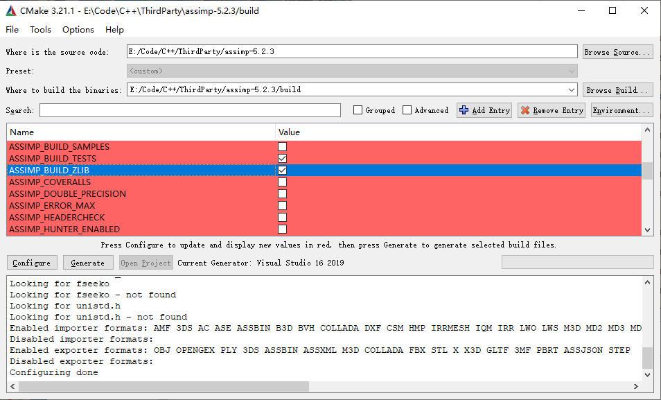
与此同时我们要找到CMAKE_INSTALL_PREFIX确定Assimp安装的位置,默认为C:/Program Files (x86)/Assimp,当然你也可以进行更改,但需要记住安装的位置在后面教程项目配置的时候需要用到。
然后ASSIMP_BUILD_ASSIMP_TOOLS这个选项也推荐关掉
如果你想使用Assimp的模型查看器的话,勾选ASSIMP_BUILD_ASSIMP_VIEW,但前提是需要安装Microsoft DirectX SDK。
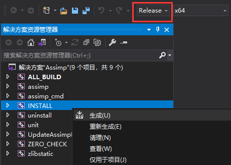
完成上述配置后点击Generate就会生成Visual Studio项目。然后我们需要以管理员身份打开Visual Studio,并打开Assimp.sln。
我们需要分别以Release x64和Debug x64配置各生成一次,右键INSTALL生成就会自动编译并将生成的静态库、动态库以及头文件复制到CMAKE_INSTALL_PREFIX确定的路径中:
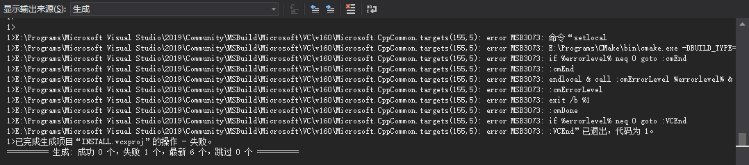
如果出现以下情况也不代表就是失败了,实际上也已经完成了复制:
完成两次生成后,应该去CMAKE_INSTALL_PREFIX(C:/Program Files (x86)/Assimp)的路径检查文件情况,应该可以看到文件结构大致如下:
Assimp
|---bin
|   |---assimp-vc14*-mt.dll
|   |---assimp-vc14*-mtd.dll
|---include
|   |---assimp
|---lib
    |---cmake
    |---pkgconfig
    |---assimp-vc14*-mt.lib
    |---assimp-vc14*-mtd.lib
    |---zlibstatic.lib
    |---zlibstaticd.lib
对于你的项目而言,需要引入Assimp的头文件、静态库和动态库,具体过程如下。
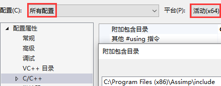
在项目属性页中,选择C/C++ → 常规 → 附加包含目录,添加Assimp头文件所在路径:
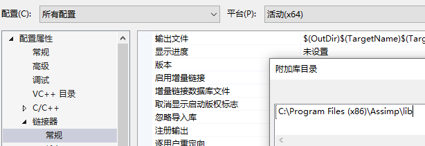
选择链接器 → 常规 → 附加库目录,添加Assimp库目录:
然后是动态库。一般在提供他人程序的时候也要在exe路径放所需的动态库,但现在在学习的过程中我们可能会产生很多项目,但又不希望为每个项目都复制dll过来,为此我们可以让程序在运行的时候去额外寻找指定路径的dll。
选择调试 → 环境,添加PATH=C:\Program Files (x86)\Assimp\bin,这样程序运行的时候就会额外在该路径寻找动态库了,但每个使用Assimp的项目都需要进行这样的设置,其属性保存在*.vcxproj.user中
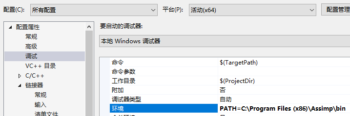
这样你编译好的程序在运行的时候就会额外寻找该路径下的dll了。
编写cmake给你的项目引入assimp
由于assimp提供了cmake,如果你的项目是通过cmake来生成的话,自然就会想到是不是能够用cmake去调assimp的cmake?答案是肯定的。
首先在你的CMakeLists.txt中添加这段,确保你的项目路径中包含了assimp:
add_subdirectory("assimp")
target_link_libraries(TargetName assimp)
这样相当于你在cmake-gui直接配置、生成,然后产生的那些子项目现在全部都包含到了你的解决方案里。但是这里面有很多的项目我们是不需要的,为此我们得在cmake中设置各种选项,下面是一种个人推荐的做法:
set(ASSIMP_BUILD_ZLIB ON)
set(ASSIMP_BUILD_ASSIMP_TOOLS OFF)
set(ASSIMP_BUILD_TESTS OFF)
set(ASSIMP_INSTALL OFF)
set(ASSIMP_INJECT_DEBUG_POSTFIX OFF)

add_subdirectory("assimp")
target_link_libraries(TargetName assimp)
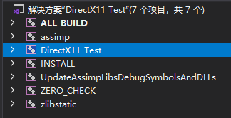
这时候你生成的解决方案中,有关于Assimp的项目就只剩下assimp、UpdateAssimpLibsDebugSymbolsAndDLLs和zlibstatic了。但直接生成解决方案的话会找不到dll,为此我们还要在cmake中能够自动配置调试环境。完整的cmake代码如下:
set(ASSIMP_BUILD_ZLIB ON)
set(ASSIMP_BUILD_ASSIMP_TOOLS OFF)
set(ASSIMP_BUILD_TESTS OFF)
set(ASSIMP_INSTALL OFF)
set(ASSIMP_INJECT_DEBUG_POSTFIX OFF)

add_subdirectory("assimp")
target_link_libraries(TargetName assimp)
set_target_properties(TargetName PROPERTIES VS_DEBUGGER_ENVIRONMENT "PATH=${ASSIMP_LIBRARY_OUTPUT_DIRECTORY}/$<IF:$<CONFIG:Debug>,Debug,Release>")
然后就可以看到你的项目已经包含了assimp,并且应该可以在项目属性页的调试、C/C++附加库目录、链接器附加依赖项都应该包含了assimp的路径(更多的图就不放了,自行检查)。
现在你的项目应该就可以编译完直接运行了。光是这短短8句话,就花费了我很长的时间去探寻。
如果要打包程序,记得去assimp/bin/Release把dll复制一份到你的exe旁。
Assimp的统一模型格式
当使用Assimp导入一个模型的时候,它通常会将整个模型加载进一个场景aiScene当中。下图描述Assimp的存储结构:
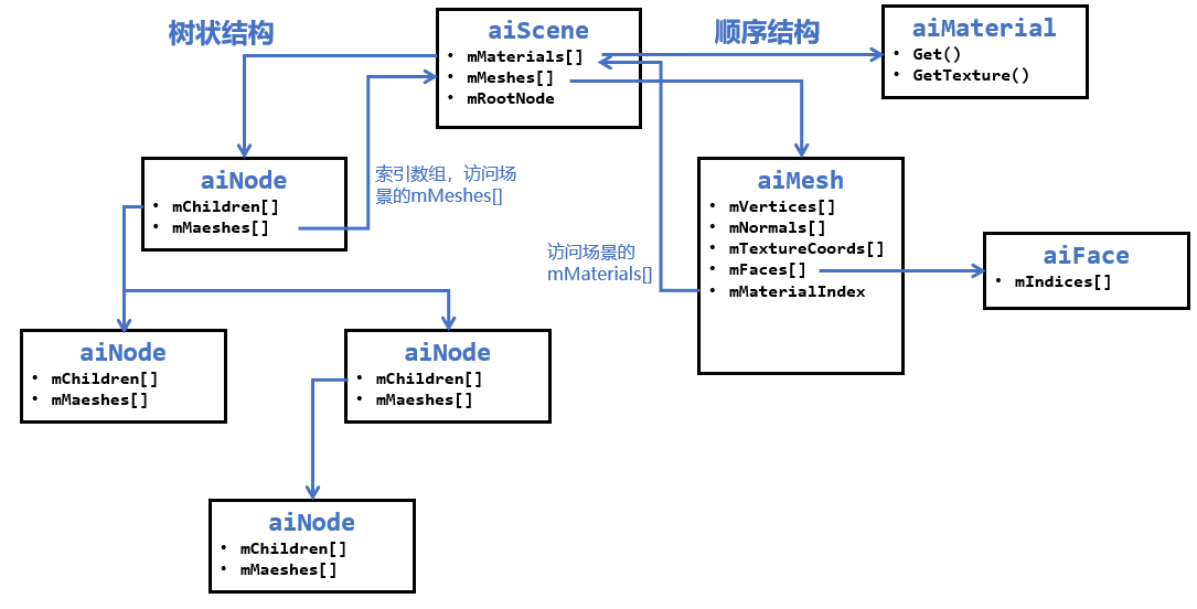
可以看到,在Assimp的场景中存储了所有的模型和材质,并且是以数组的方式存储的。然而有些模型文件是树状结构的,在这里Assimp也支持树状结构,只不过存储的网格模型是以索引的方式,需要用户对。为了方便,教程项目会将模型和材质数据进行数组方式的存储和解析。
Assimp模型导入
Assimp导入模型的实现存放在ModelManager类中。现在我们需要使用Assimp的Importer来导入一个模型:
#include <assimp/Importer.hpp>
#include <assimp/postprocess.h>
#include <assimp/scene.h>

using namespace Assimp;
Importer importer;
// 去掉里面的点、线图元
importer.SetPropertyInteger(AI_CONFIG_PP_SBP_REMOVE, aiPrimitiveType_LINE | aiPrimitiveType_POINT);
auto pAssimpScene = importer.ReadFile(filename.data(),
    aiProcess_ConvertToLeftHanded |     // 转为左手系
    aiProcess_GenBoundingBoxes |        // 获取碰撞盒
    aiProcess_Triangulate |             // 将多边形拆分
    aiProcess_ImproveCacheLocality |    // 改善缓存局部性
    aiProcess_SortByPType);             // 按图元顶点数排序用于移除非三角形图元
由于读取的模型有可能是左手系的,也有可能是右手系的,甚至有的模型三角形绕序也不一样。对DirectX来说,常用的是左手系及顺时针三角形绕序,我们可以使用aiProcess_ConvertToLeftHanded宏将其处理成上述所说的左手系和顺时针绕序。
然后我们需要检查是否成功读取模型,且模型是否完整:
if (pAssimpScene && !(pAssimpScene->mFlags & AI_SCENE_FLAGS_INCOMPLETE) && pAssimpScene->HasMeshes())
{
    // ...
}
接下来我们定义了MeshData和Material结构体,将Assimp的统一模型格式转化成DirectX11所需的数据格式:
// 获取ID
using XID = size_t;
inline XID StringToID(std::string_view str)
{
    static std::hash<std::string_view> hash;
    return hash(str);
}

template<class T, class V>
struct IsVariantMember;

template<class T, class... ALL_V>
struct IsVariantMember<T, std::variant<ALL_V...>> : public std::disjunction<std::is_same<T, ALL_V>...> {};

using Property = std::variant<
    int, uint32_t, float, DirectX::XMFLOAT4, DirectX::XMFLOAT4X4,
    std::vector<float>, std::vector<DirectX::XMFLOAT4>, std::vector<DirectX::XMFLOAT4X4>,
    std::string>;

class Material
{
public:
    Material() = default;

    void Clear()
    {
        m_Properties.clear();
    }

    template<class T>
    void Set(std::string_view name, const T& value)
    {
        static_assert(IsVariantMember<T, Property>::value, "Type T isn't one of the Property types!");
        m_Properties[StringToID(name)] = value;
    }

    template<class T>
    const T& Get(std::string_view name) const
    {
        auto it = m_Properties.find(StringToID(name));
        return std::get<T>(it->second);
    }

    template<class T>
    bool Has(std::string_view name) const
    {
        auto it = m_Properties.find(StringToID(name));
        if (it == m_Properties.end() || !std::holds_alternative<T>(it->second))
            return false;
        return true;
    }

    bool HasProperty(std::string_view name) const
    {
        return m_Properties.find(StringToID(name)) != m_Properties.end();
    }

private:

    std::unordered_map<XID, Property> m_Properties;
};
而网格的顶点在这里我们按每个属性单独生成一个Buffer,因为Assimp对于顶点也是按不同的属性分开存储的。
struct MeshData
{
    // 使用模板别名(C++11)简化类型名
    template <class T>
    using ComPtr = Microsoft::WRL::ComPtr<T>;

    ComPtr<ID3D11Buffer> m_pVertices;
    ComPtr<ID3D11Buffer> m_pNormals;
    std::vector<ComPtr<ID3D11Buffer>> m_pTexcoordArrays;
    ComPtr<ID3D11Buffer> m_pTangents;
    ComPtr<ID3D11Buffer> m_pColors;

    ComPtr<ID3D11Buffer> m_pIndices;
    uint32_t m_VertexCount = 0;
    uint32_t m_IndexCount = 0;
    uint32_t m_MaterialIndex = 0;

    DirectX::BoundingBox m_BoundingBox;
    bool m_InFrustum = true;
};
模型本身我们也遵循Assimp的顺序存储结构:
struct Model
{
    std::vector<Material> materials;
    std::vector<MeshData> meshdatas;
    DirectX::BoundingBox boundingbox;
};
接下来我们先处理模型相关的属性:
Model model;

model.meshdatas.resize(pAssimpScene->mNumMeshes);
model.materials.resize(pAssimpScene->mNumMaterials);
for (uint32_t i = 0; i < pAssimpScene->mNumMeshes; ++i)
{
    auto& mesh = model.meshdatas[i];

    auto pAiMesh = pAssimpScene->mMeshes[i];
    uint32_t numVertices = pAiMesh->mNumVertices;

    CD3D11_BUFFER_DESC bufferDesc(0, D3D11_BIND_VERTEX_BUFFER);
    D3D11_SUBRESOURCE_DATA initData{ nullptr, 0, 0 };
    // 位置
    if (pAiMesh->mNumVertices > 0)
    {
        initData.pSysMem = pAiMesh->mVertices;
        bufferDesc.ByteWidth = numVertices * sizeof(XMFLOAT3);
        m_pDevice->CreateBuffer(&bufferDesc, &initData, mesh.m_pVertices.GetAddressOf());

        BoundingBox::CreateFromPoints(mesh.m_BoundingBox, numVertices,
                                      (const XMFLOAT3*)pAiMesh->mVertices, sizeof(XMFLOAT3));
        if (i == 0)
            model.boundingbox = mesh.m_BoundingBox;
        else
            model.boundingbox.CreateMerged(model.boundingbox, model.boundingbox, mesh.m_BoundingBox);
    }

    // 法线
    if (pAiMesh->HasNormals())
    {
        initData.pSysMem = pAiMesh->mNormals;
        bufferDesc.ByteWidth = numVertices * sizeof(XMFLOAT3);
        m_pDevice->CreateBuffer(&bufferDesc, &initData, mesh.m_pNormals.GetAddressOf());
    }

    // 切线和副切线
    if (pAiMesh->HasTangentsAndBitangents())
    {
        std::vector<XMFLOAT4> tangents(numVertices, XMFLOAT4(0.0f, 0.0f, 0.0f, 1.0f));
        for (uint32_t i = 0; i < pAiMesh->mNumVertices; ++i)
        {
            memcpy_s(&tangents[i], sizeof(XMFLOAT3),
                     pAiMesh->mTangents + i, sizeof(XMFLOAT3));
        }

        initData.pSysMem = tangents.data();
        bufferDesc.ByteWidth = pAiMesh->mNumVertices * sizeof(XMFLOAT4);
        m_pDevice->CreateBuffer(&bufferDesc, &initData, mesh.m_pTangents.GetAddressOf());

        for (uint32_t i = 0; i < pAiMesh->mNumVertices; ++i)
        {
            memcpy_s(&tangents[i], sizeof(XMFLOAT3),
                     pAiMesh->mBitangents + i, sizeof(XMFLOAT3));
        }
        m_pDevice->CreateBuffer(&bufferDesc, &initData, mesh.m_pBitangents.GetAddressOf());
    }

    // 纹理坐标
    uint32_t numUVs = 8;
    while (numUVs && !pAiMesh->HasTextureCoords(numUVs - 1))
        numUVs--;

    if (numUVs > 0)
    {
        mesh.m_pTexcoordArrays.resize(numUVs);
        for (uint32_t i = 0; i < numUVs; ++i)
        {
            std::vector<XMFLOAT2> uvs(numVertices);
            for (uint32_t j = 0; j < numVertices; ++j)
            {
                memcpy_s(&uvs[j], sizeof(XMFLOAT2),
                         pAiMesh->mTextureCoords[i] + j, sizeof(XMFLOAT2));
            }
            initData.pSysMem = uvs.data();
            bufferDesc.ByteWidth = numVertices * sizeof(XMFLOAT2);
            m_pDevice->CreateBuffer(&bufferDesc, &initData, mesh.m_pTexcoordArrays[i].GetAddressOf());
        }
    }

    // 索引
    uint32_t numFaces = pAiMesh->mNumFaces;
    uint32_t numIndices = numFaces * 3;
    if (numFaces > 0)
    {
        mesh.m_IndexCount = numIndices;
        if (numIndices < 65535)
        {
            std::vector<uint16_t> indices(numIndices);
            for (size_t i = 0; i < numFaces; ++i)
            {
                indices[i * 3] = static_cast<uint16_t>(pAiMesh->mFaces[i].mIndices[0]);
                indices[i * 3 + 1] = static_cast<uint16_t>(pAiMesh->mFaces[i].mIndices[1]);
                indices[i * 3 + 2] = static_cast<uint16_t>(pAiMesh->mFaces[i].mIndices[2]);
            }
            bufferDesc = CD3D11_BUFFER_DESC(numIndices * sizeof(uint16_t), D3D11_BIND_INDEX_BUFFER);
            initData.pSysMem = indices.data();
            m_pDevice->CreateBuffer(&bufferDesc, &initData, mesh.m_pIndices.GetAddressOf());
        }
        else
        {
            std::vector<uint32_t> indices(numIndices);
            for (size_t i = 0; i < numFaces; ++i)
            {
                memcpy_s(indices.data() + i * 3, sizeof(uint32_t) * 3,
                         pAiMesh->mFaces[i].mIndices, sizeof(uint32_t) * 3);
            }
            bufferDesc = CD3D11_BUFFER_DESC(numIndices * sizeof(uint32_t), D3D11_BIND_INDEX_BUFFER);
            initData.pSysMem = indices.data();
            m_pDevice->CreateBuffer(&bufferDesc, &initData, mesh.m_pIndices.GetAddressOf());
        }
    }

    // 材质索引
    mesh.m_MaterialIndex = pAiMesh->mMaterialIndex;
}
这里规定如果索引数小于等于65535,则每个索引使用2字节存储,否则使用4字节存储。
然后是材质相关的属性,主要可以分为值和纹理。对于值,我们可以使用Get()方法,通过AI_MATKEY尝试获取;对于纹理,我们可以使用GetTexture()方法,通过aiTextureType尝试获取:
namespace fs = std::filesystem;
for (uint32_t i = 0; i < pAssimpScene->mNumMaterials; ++i)
{
    auto& material = model.materials[i];

    auto pAiMaterial = pAssimpScene->mMaterials[i];
    XMFLOAT4 vec{};
    float value{};
    uint32_t boolean{};
    uint32_t num = 3;

    if (aiReturn_SUCCESS == pAiMaterial->Get(AI_MATKEY_COLOR_AMBIENT, (float*)&vec, &num))
        material.Set("$AmbientColor", vec);
    if (aiReturn_SUCCESS == pAiMaterial->Get(AI_MATKEY_COLOR_DIFFUSE, (float*)&vec, &num))
        material.Set("$DiffuseColor", vec);
    if (aiReturn_SUCCESS == pAiMaterial->Get(AI_MATKEY_COLOR_SPECULAR, (float*)&vec, &num))
        material.Set("$SpecularColor", vec);
    if (aiReturn_SUCCESS == pAiMaterial->Get(AI_MATKEY_SPECULAR_FACTOR, value))
        material.Set("$SpecularFactor", value);
    if (aiReturn_SUCCESS == pAiMaterial->Get(AI_MATKEY_COLOR_EMISSIVE, (float*)&vec, &num))
        material.Set("$EmissiveColor", vec);
    if (aiReturn_SUCCESS == pAiMaterial->Get(AI_MATKEY_COLOR_TRANSPARENT, (float*)&vec, &num))
        material.Set("$TransparentColor", vec);
    if (aiReturn_SUCCESS == pAiMaterial->Get(AI_MATKEY_COLOR_REFLECTIVE, (float*)&vec, &num))
        material.Set("$ReflectiveColor", vec);
    if (pAiMaterial->GetTextureCount(aiTextureType_DIFFUSE) > 0)
    {
        aiString aiPath;
        pAiMaterial->GetTexture(aiTextureType_DIFFUSE, 0, &aiPath);
        fs::path tex_filename = filename;
        tex_filename = tex_filename.parent_path() / aiPath.C_Str();
        TextureManager::Get().CreateTexture(tex_filename.string(), true, true);
        material.Set("$Diffuse", tex_filename.string());
    }
    if (pAiMaterial->GetTextureCount(aiTextureType_NORMALS) > 0)
    {
        aiString aiPath;
        pAiMaterial->GetTexture(aiTextureType_NORMALS, 0, &aiPath);
        fs::path tex_filename = filename;
        tex_filename = tex_filename.parent_path() / aiPath.C_Str();
        TextureManager::Get().CreateTexture(tex_filename.string());
        material.Set("$Normal", tex_filename.string());
    }
}
后续随着项目的复杂,这里需要读取判断的内容也会变多。
多顶点缓冲区输入
之前我们提到,在输入装配阶段中提供了16个输入槽,这意味着我们最多可以同时绑定16个顶点缓冲区作为输入。那这时候如果我们使用多个顶点缓冲区作为输入会产生什么样的结果呢?
现在假定着色器需要使用的顶点结构为:
| 索引 | 顶点位置 | 顶点法向量 | 顶点UV |
|---|---|---|---|
| 0 | P1 | N1 | T0 |
| 1 | P2 | N2 | T1 |
| 2 | P3 | N3 | T2 |
如今我们有两种方式输入顶点的方式,见下图:
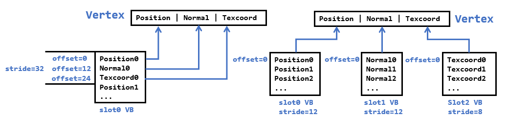
左边的是我们之前常用的方式,在一个顶点缓冲区内按顶点、法线、UV交替存放,然后设置正确的stride和offset来读取对应区域的数据来组成顶点。而现在我们拿到的数据是顶点数组、法线数组和UV数组,并分别创建各自的顶点缓冲区,然后在输入装配阶段绑定多个顶点缓冲区,此时我们只需要让各自的offset为0,只需要设置正确的stride即可。
回顾一下顶点输入布局描述的结构:
 typedef struct D3D11_INPUT_ELEMENT_DESC
 {
    LPCSTR SemanticName;    // 语义名
    UINT SemanticIndex;     // 语义名对应的索引值
    DXGI_FORMAT Format;     // DXGI数据格式
    UINT InputSlot;         // 输入槽
    UINT AlignedByteOffset; // 对齐的字节偏移量
    D3D11_INPUT_CLASSIFICATION InputSlotClass;  // 输入槽类别(此时为顶点)
    UINT InstanceDataStepRate;  // 忽略(0)
 } 	D3D11_INPUT_ELEMENT_DESC;
现在我们可以在输入布局中这样指定,并且我们也不需要去计算每个输入槽对应的字节偏移了:
| 语义 | 语义索引 | 数据格式 | 输入槽 | 该输入槽对应的字节偏移 |
|---|---|---|---|---|
| POSITION | 0 | R32G32B32_FLOAT | 0 | 0 |
| NORMAL | 0 | R32G32B32_FLOAT | 1 | 0 |
| TEXCOORD | 0 | R32G32_FLOAT | 2 | 0 |
这样,下面在HLSL的顶点结构体数据实际上来源于三个输入槽:
struct VertexPosNormalColor
{
	float3 pos : POSITION;		// 来自输入槽0
	float3 normal : NORMAL;		// 来自输入槽1
	float4 tex : TEXCOORD;		// 来自输入槽2
};
然后,输入装配器就会根据输入布局,以及索引值来抽取对应数据,最终构造出来的顶点数据流和一开始给出的表格数据是一致的。当然,我们也可以将这些数据拼成单个顶点缓冲区,但这样就无法应对顶点结构复杂多变的shader了。
然后在输入装配阶段,传入这些顶点缓冲区,并设置好各自的步幅和偏移即可:
ID3D11Buffer* pVBs[] = { pPosBuffer, pNormalBuffer, pTexBuffer };
uint32_t strides[] = { 12, 12, 8 };
uint32_t offsets[] = { 0, 0, 0 };
m_pd3dImmediateContext->IASetVertexBuffers(0, ARRAYSIZE(pVBs), pVBs, strides, offsets);
新的EffectHelper
本章开始的代码引入了新的EffectHelper来管理着色器所需的资源,并且由于它能够支持对着色器反射,我们可以在C++获取到着色器的变量名,用户可以直接通过这些变量名来预先设置管线所需的资源。此外,我们可以无需操心常量缓冲区的创建和设置了。这里我们不会对EffectHelper的内部实现做解析,读者只需要知道如何使用即可。
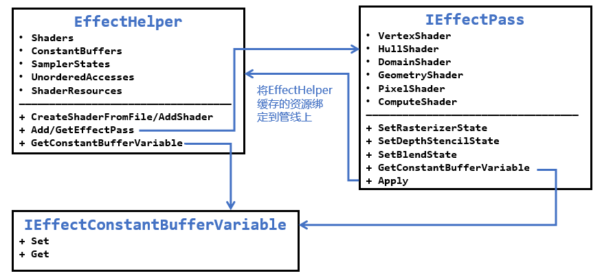
EffectHelper内部负责管理着色器需要用到的各种资源,如常量缓冲区、纹理输入、采样器等。而一个IEffectPass代表一次绘制所需要用到的各个着色器、光栅化状态、深度/模板状态和混合状态。通过EffectHelper可以获取到全局的常量缓冲区变量,而IEffectPass可以获取到和着色器相关的uniform变量。在完成这些设置后,调用IEffectPass::Apply就会将EffectHelper缓存的各项资源绑定到渲染管线上。基本顺序为:
- 添加各种shader,让其进行着色器反射,但需要注意不同的shader中,同一个register对应的变量名和类型都应该相同,cbuffer布局也应该相同。若有不同则应该归类于不同的
EffectHelper - 根据已经添加的shader,创建一系列需要用到EffectPass,每个EffectPass需要指定所需的着色器和渲染状态
- 根据名称去设置着色器常量、采样器状态、着色器资源等
- 要使用某个Pass,从EffectHelper获取并进行Apply,这样就会将shader、常量缓冲区、采样器、着色器资源等绑定到渲染管线上
此外,为了简化调用过程,这里为每个EffectHelper对象配备一个具体的Effect单例类,负责设置好EffectHelper所需的东西。这些Effect需要继承IEffect接口类,除此之外,目前还引入了IEffectTransform、IEffectMaterial和IEffectMeshData接口类来统一变换的设置、材质和模型的读取和解析,根据需要来继承。
在IEffect.h内我们定义了下述结构体:
struct MeshDataInput
{
    std::vector<ID3D11Buffer*> pVertexBuffers;
    ID3D11Buffer* pIndexBuffer = nullptr;
    std::vector<uint32_t> strides;
    std::vector<uint32_t> offsets;
    uint32_t indexCount = 0;
};

class IEffect
{
public:
    IEffect() = default;
    virtual ~IEffect() = default;
    // 不允许拷贝,允许移动
    IEffect(const IEffect&) = delete;
    IEffect& operator=(const IEffect&) = delete;
    IEffect(IEffect&&) = default;
    IEffect& operator=(IEffect&&) = default;

    // 更新并绑定常量缓冲区
    virtual void Apply(ID3D11DeviceContext * deviceContext) = 0;
};

class IEffectTransform
{
public:
    virtual void XM_CALLCONV SetWorldMatrix(DirectX::FXMMATRIX W) = 0;
    virtual void XM_CALLCONV SetViewMatrix(DirectX::FXMMATRIX V) = 0;
    virtual void XM_CALLCONV SetProjMatrix(DirectX::FXMMATRIX P) = 0;
};

class IEffectMaterial
{
public:
    virtual void SetMaterial(const Material& material) = 0;
};

class IEffectMeshData
{
public:
    virtual MeshDataInput GetInputData(const MeshData& meshData) = 0;
};
这里我们继续使用之前BasicEffect的名字,接口部分也和前面的相差不大:
class BasicEffect : public IEffect, public IEffectTransform,
    public IEffectMaterial, public IEffectMeshData
{
public:
    BasicEffect();
    virtual ~BasicEffect() override;

    BasicEffect(BasicEffect&& moveFrom) noexcept;
    BasicEffect& operator=(BasicEffect&& moveFrom) noexcept;

    // 获取单例
    static BasicEffect& Get();

    // 初始化所需资源
    bool InitAll(ID3D11Device* device);

    //
    // IEffectTransform
    //

    void XM_CALLCONV SetWorldMatrix(DirectX::FXMMATRIX W) override;
    void XM_CALLCONV SetViewMatrix(DirectX::FXMMATRIX V) override;
    void XM_CALLCONV SetProjMatrix(DirectX::FXMMATRIX P) override;

    //
    // IEffectMaterial
    //

    void SetMaterial(const Material& material) override;

    //
    // IEffectMeshData
    //

    MeshDataInput GetInputData(const MeshData& meshData) override;


    //
    // BasicEffect
    //

    // 默认状态来绘制
    void SetRenderDefault(ID3D11DeviceContext* deviceContext);

    // 各种类型灯光允许的最大数目
    static const int maxLights = 5;

    void SetDirLight(uint32_t pos, const DirectionalLight& dirLight);
    void SetPointLight(uint32_t pos, const PointLight& pointLight);
    void SetSpotLight(uint32_t pos, const SpotLight& spotLight);

    void SetEyePos(const DirectX::XMFLOAT3& eyePos);

    // 应用常量缓冲区和纹理资源的变更
    void Apply(ID3D11DeviceContext* deviceContext) override;

private:
    class Impl;
    std::unique_ptr<Impl> pImpl;
};
在初始化阶段,我们需要为EffectHelper添加shader,创建顶点布局和EffectPasses
template<size_t numElements>
using D3D11_INPUT_ELEMENT_DESC_ARRAY = const D3D11_INPUT_ELEMENT_DESC(&)[numElements];

struct VertexPosNormalTex
{
    // ...
    DirectX::XMFLOAT3 pos;
    DirectX::XMFLOAT3 normal;
    DirectX::XMFLOAT2 tex;

    static D3D11_INPUT_ELEMENT_DESC_ARRAY<3> GetInputLayout()
    {
        static const D3D11_INPUT_ELEMENT_DESC inputLayout[3] = {
            { "POSITION", 0, DXGI_FORMAT_R32G32B32_FLOAT, 0, 0, D3D11_INPUT_PER_VERTEX_DATA, 0 },
            { "NORMAL", 0, DXGI_FORMAT_R32G32B32_FLOAT, 1, 0, D3D11_INPUT_PER_VERTEX_DATA, 0 },
            { "TEXCOORD", 0, DXGI_FORMAT_R32G32_FLOAT, 2, 0, D3D11_INPUT_PER_VERTEX_DATA, 0 }
        };
        return inputLayout;
    }
};

//
// BasicEffect::Impl 需要先于BasicEffect的定义
//

class BasicEffect::Impl
{
public:
    // 必须显式指定
    Impl() {}
    ~Impl() = default;

public:
    template<class T>
    using ComPtr = Microsoft::WRL::ComPtr<T>;

    std::unique_ptr<EffectHelper> m_pEffectHelper;

    std::shared_ptr<IEffectPass> m_pCurrEffectPass;

    ComPtr<ID3D11InputLayout> m_pVertexPosNormalTexLayout;

    XMFLOAT4X4 m_World{}, m_View{}, m_Proj{};
};

bool BasicEffect::InitAll(ID3D11Device* device)
{
    if (!device)
        return false;

    if (!RenderStates::IsInit())
        throw std::exception("RenderStates need to be initialized first!");

    pImpl->m_pEffectHelper = std::make_unique<EffectHelper>();

    Microsoft::WRL::ComPtr<ID3DBlob> blob;
    // 创建顶点着色器
    pImpl->m_pEffectHelper->CreateShaderFromFile("BasicVS", L"Shaders/Basic_VS.cso", device,
        "VS", "vs_5_0", nullptr, blob.GetAddressOf());
    // 创建顶点布局
    HR(device->CreateInputLayout(VertexPosNormalTex::GetInputLayout(), ARRAYSIZE(VertexPosNormalTex::GetInputLayout()),
        blob->GetBufferPointer(), blob->GetBufferSize(), pImpl->m_pVertexPosNormalTexLayout.GetAddressOf()));

    // 创建像素着色器
    pImpl->m_pEffectHelper->CreateShaderFromFile("BasicPS", L"Shaders/Basic_PS.cso", device,
        "ForwardPS", "ps_5_0");


    // 创建通道
    EffectPassDesc passDesc;
    passDesc.nameVS = "BasicVS";
    passDesc.namePS = "BasicPS";
    pImpl->m_pEffectHelper->AddEffectPass("Basic", device, &passDesc);

    pImpl->m_pEffectHelper->SetSamplerStateByName("g_Sam", RenderStates::SSLinearWrap.Get());


    return true;
}
然后是一些设置和获取方法的使用示例:
void XM_CALLCONV BasicEffect::SetWorldMatrix(DirectX::FXMMATRIX W)
{
    XMStoreFloat4x4(&pImpl->m_World, W);
}

void XM_CALLCONV BasicEffect::SetViewMatrix(DirectX::FXMMATRIX V)
{
    XMStoreFloat4x4(&pImpl->m_View, V);
}

void XM_CALLCONV BasicEffect::SetProjMatrix(DirectX::FXMMATRIX P)
{
    XMStoreFloat4x4(&pImpl->m_Proj, P);
}

void BasicEffect::SetMaterial(const Material& material)
{
    TextureManager& tm = TextureManager::Get();

    PhongMaterial phongMat{};
    phongMat.ambient = material.Get<XMFLOAT4>("$AmbientColor");
    phongMat.diffuse = material.Get<XMFLOAT4>("$DiffuseColor");
    phongMat.specular = material.Get<XMFLOAT4>("$SpecularColor");
    phongMat.specular.w = material.Has<float>("$SpecularFactor") ? material.Get<float>("$SpecularFactor") : 1.0f;
    pImpl->m_pEffectHelper->GetConstantBufferVariable("g_Material")->SetRaw(&phongMat);

    auto pStr = material.TryGet<std::string>("$Diffuse");
    pImpl->m_pEffectHelper->SetShaderResourceByName("g_DiffuseMap", pStr ? tm.GetTexture(*pStr) : tm.GetNullTexture());
}

MeshDataInput BasicEffect::GetInputData(const MeshData& meshData)
{
    MeshDataInput input;
    input.pVertexBuffers = {
        meshData.m_pVertices.Get(),
        meshData.m_pNormals.Get(),
        meshData.m_pTexcoordArrays.empty() ? nullptr : meshData.m_pTexcoordArrays[0].Get()
    };
    input.strides = { 12, 12, 8 };
    input.offsets = { 0, 0, 0 };

    input.pIndexBuffer = meshData.m_pIndices.Get();
    input.indexCount = meshData.m_IndexCount;

    return input;
}

void BasicEffect::SetDirLight(uint32_t pos, const DirectionalLight& dirLight)
{
    pImpl->m_pEffectHelper->GetConstantBufferVariable("g_DirLight")->SetRaw(&dirLight, (sizeof dirLight) * pos, sizeof dirLight);
}

void BasicEffect::SetPointLight(uint32_t pos, const PointLight& pointLight)
{
    pImpl->m_pEffectHelper->GetConstantBufferVariable("g_PointLight")->SetRaw(&pointLight, (sizeof pointLight) * pos, sizeof pointLight);
}

void BasicEffect::SetSpotLight(uint32_t pos, const SpotLight& spotLight)
{
    pImpl->m_pEffectHelper->GetConstantBufferVariable("g_SpotLight")->SetRaw(&spotLight, (sizeof spotLight) * pos, sizeof spotLight);
}

void BasicEffect::SetEyePos(const DirectX::XMFLOAT3& eyePos)
{
    pImpl->m_pEffectHelper->GetConstantBufferVariable("g_EyePosW")->SetFloatVector(3, reinterpret_cast<const float*>(&eyePos));
}

void BasicEffect::SetRenderDefault(ID3D11DeviceContext* deviceContext)
{
    deviceContext->IASetInputLayout(pImpl->m_pVertexPosNormalTexLayout.Get());
    pImpl->m_pCurrEffectPass = pImpl->m_pEffectHelper->GetEffectPass("Basic");
    deviceContext->IASetPrimitiveTopology(D3D11_PRIMITIVE_TOPOLOGY_TRIANGLELIST);
}
最后Apply方法会调用当前IEffectPass的Apply:
void BasicEffect::Apply(ID3D11DeviceContext* deviceContext)
{
    XMMATRIX W = XMLoadFloat4x4(&pImpl->m_World);
    XMMATRIX V = XMLoadFloat4x4(&pImpl->m_View);
    XMMATRIX P = XMLoadFloat4x4(&pImpl->m_Proj);

    XMMATRIX VP = V * P;
    XMMATRIX WInvT = XMath::InverseTranspose(W);

    W = XMMatrixTranspose(W);
    VP = XMMatrixTranspose(VP);
    WInvT = XMMatrixTranspose(WInvT);

    pImpl->m_pEffectHelper->GetConstantBufferVariable("g_WorldInvTranspose")->SetFloatMatrix(4, 4, (FLOAT*)&WInvT);
    pImpl->m_pEffectHelper->GetConstantBufferVariable("g_ViewProj")->SetFloatMatrix(4, 4, (FLOAT*)&VP);
    pImpl->m_pEffectHelper->GetConstantBufferVariable("g_World")->SetFloatMatrix(4, 4, (FLOAT*)&W);

    if (pImpl->m_pCurrEffectPass)
        pImpl->m_pCurrEffectPass->Apply(deviceContext);
}
shader读取纹理的优化
考虑到有的模型可能不存在漫反射贴图,我们可以为模型添加常量色。一开始我们可能会这样写:
float4 diffuse = float4(1.0f, 1.0f, 1.0f, 1.0f);
uint2 texWidth, texHeight;
g_DiffuseMap.GetDimensions(texWidth, texHeight);
if (texWidth > 0 && texHeight > 0)
{
	diffuse = g_DiffuseMap.Sample(g_Sam, pIn.texcoord);
}
但引入分支会引发性能问题。可以考虑创建一个1x1大小的、RGBA均为255的白纹理,然后如果模型没有漫反射纹理则传入这个白纹理。通过TextureManager::GetNullTexture来获取:
auto pStr = material.TryGet<std::string>("$Diffuse");
pImpl->m_pEffectHelper->SetShaderResourceByName("g_DiffuseMap", pStr ? tm.GetTexture(*pStr) : tm.GetNullTexture());
然后shader中只需要一句话:
float4 diffuse = g_DiffuseMap.Sample(g_Sam, pIn.texcoord);
类似的,我们可以用这种方式来支持纹理颜色或常量颜色的设置,使用下面的代码:
// 使用纹理时,将g_DiffuseColor设为(1.0f, 1.0f, 1.0f, 1.0f)
// 使用常量颜色时,将g_DiffuseMap设为1x1白纹理
float4 diffuse = g_DiffuseMap.Sample(g_Sam, pIn.texcoord) * g_DiffuseColor;
GameObject类的变化
现在GameObject类主要存有Model和Transform的数据,目前主要关注的是GameObject::Draw方法(有所删减):
void GameObject::Draw(ID3D11DeviceContext * deviceContext, IEffect& effect)
{
    if (/* ... */!deviceContext)
        return;
    size_t sz = m_pModel->meshdatas.size();
    for (size_t i = 0; i < sz; ++i)
    {
        IEffectMeshData* pEffectMeshData = dynamic_cast<IEffectMeshData*>(&effect);
        if (!pEffectMeshData)
            continue;

        IEffectMaterial* pEffectMaterial = dynamic_cast<IEffectMaterial*>(&effect);
        if (pEffectMaterial)
            pEffectMaterial->SetMaterial(m_pModel->materials[m_pModel->meshdatas[i].m_MaterialIndex]);

        IEffectTransform* pEffectTransform = dynamic_cast<IEffectTransform*>(&effect);
        if (pEffectTransform)
            pEffectTransform->SetWorldMatrix(m_Transform.GetLocalToWorldMatrixXM());

        effect.Apply(deviceContext);

        MeshDataInput input = pEffectMeshData->GetInputData(m_pModel->meshdatas[i]);
        {
            deviceContext->IASetVertexBuffers(0, (uint32_t)input.pVertexBuffers.size(),
                input.pVertexBuffers.data(), input.strides.data(), input.offsets.data());
            deviceContext->IASetIndexBuffer(input.pIndexBuffer, input.indexCount > 65535 ? DXGI_FORMAT_R32_UINT : DXGI_FORMAT_R16_UINT, 0);

            deviceContext->DrawIndexed(input.indexCount, 0, 0);
        }
    }
}
模型加载演示
这里我选用了之前合作项目时设计师完成的房屋模型,经过Assimp加载后进行绘制。效果如下:
DirectX11 With Windows SDK完整目录
欢迎加入QQ群: 727623616 可以一起探讨DX11,以及有什么问题也可以在这里汇报。

 浙公网安备 33010602011771号