
摘自 <<I2C-bus specification and user manual>> Rev. 6 -- 4 April 2014
1 features
1) two bus lines: SCL, SDA
2) each device is software addressable
3) multi-master
4) 100kb/s ~ Standard-mode; 3.4Mb/s ~ High-speed mode
2 protocol
2.1 signals
SDA and SCL are bidirectional lines, connected to a positive supply voltage via a current-source or pull-up resistor.
Both lines are HIGH when the bus is free.
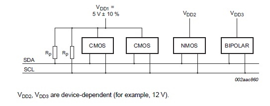
Input reference level are set as 30% and 70% of VDD, VIL = 0.3VDD, VIH = 0.7VDD
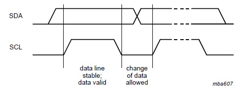
2.2 data validity
the data on SDA must be stable during the High period of SCL
the data on SDA can only change when Low period of SCL
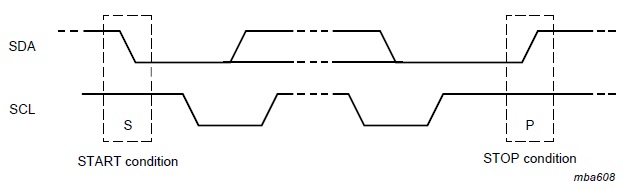
2.3 START and STOP conditions
S condition, a HIGH to LOW transition on SDA while SCL is HIGH
P condition, a LOW to HIGH transition on SDA while SCL is HIGH
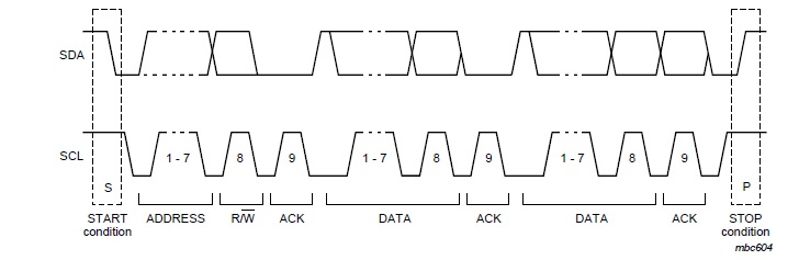
2.4 BYTE format
every byte put on the SDA line must be 8 bits long
each byte must be followed by an Acknowledge bit

If a slave cannot receive or transmit another complete byte of data until it has performed some other function, for example servicing an internal interrupt, it can hold the clock line SCL LOW to force the master into a wait state.
2.5 ACK and NACK
ACK signal (LOW): the transmitter releases the SDA line during the ack clock pulse so the receiver can pull the SDA line LOW and it remained LOW durng the HIGH period of this clock pulse.
NACK signal (HIGH): when SDA remains HIGH during this 9th clock pulse, the master can then generate either a STOP to abort the transfer, or a repeated START to start a new transfer.
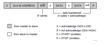
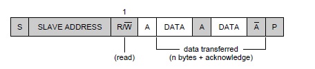
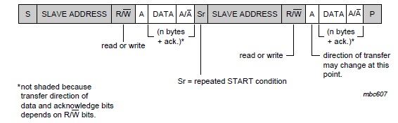
2.6 slave address and R/W bit
1) a complete data transfer
2) a master writes data into a slave
3) a master reads dta from a slave
4) combined format
原文链接: http://www.cnblogs.com/xinxue/
专注于机器视觉、OpenCV、C++ 编程

 浙公网安备 33010602011771号