
PolarFire-SoC 中断
PolarFire SoC MSS Technical Reference Manual
5 . Interrupts
第五章 中断
Each processor core supports Local and Global Interrupts. 48 interrupts from peripherals are
directly connected as Local interrupts to each processor core. Local interrupts are handled faster
than the Global interrupts. The Core Local Interrupt Controller (CLINT) block generates Software and
Timer Interrupts which are also Local interrupts.
每个处理器核心都支持本地中断和全局中断。来自外设的48个中断直接作为本地中断连接到每个处理器核心。
本地中断的处理速度比全局中断更快。核心本地中断控制器(CLINT)模块还会生成软件中断和定时器中断,这些也属于本地中断。
169 interrupts from peripherals and 16 interrupts from the CPU Core Complex blocks—DMA
Engine, BEU, and L2 Cache are connected to the Platform-Level Interrupt Controller (PLIC) as Global
interrupts. The PLIC asserts Global interrupts to a specific processor core. The user can configure
the PLIC registers to perform the following:
• Enable the required Global interrupts
• Route the interrupt to a specific core
• Assign priority to those interrupts
• Assign priority threshold levels
来自外设的169个中断以及来自CPU核心复合体模块(包括DMA引擎、BEU和L2缓存)的16个中断,作为全局中断连接到平台级中断控制器(PLIC)。
PLIC会向特定处理器核心声明全局中断。用户可通过配置PLIC寄存器实现以下功能:
• 启用所需的全局中断
• 将中断路由至指定核心
• 为中断分配优先级
• 设置优先级阈值级别
Important: Priority threshold levels isolate interrupt handling among processor cores.
重要提示:优先级阈值可在各处理器核心之间实现中断处理的隔离。
Some application critical Global interrupts can also be routed as Local interrupts. All interrupts are
synchronized with the AXI/CPU clock domain for relaxed timing requirements. For a Hart, the latency
of Global interrupts increases with the ratio of the core clock frequency to the clock frequency.
The following figure shows the interrupt scheme of the MSS.
部分应用关键的全局中断亦可配置为本地中断。所有中断均与AXI/CPU时钟域同步,以放宽时序要求。
对于硬件线程(Hart)而言,全局中断的延迟随核心时钟频率与总线时钟频率的比值增加而增大。
下图展示了MSS的中断实现方案。
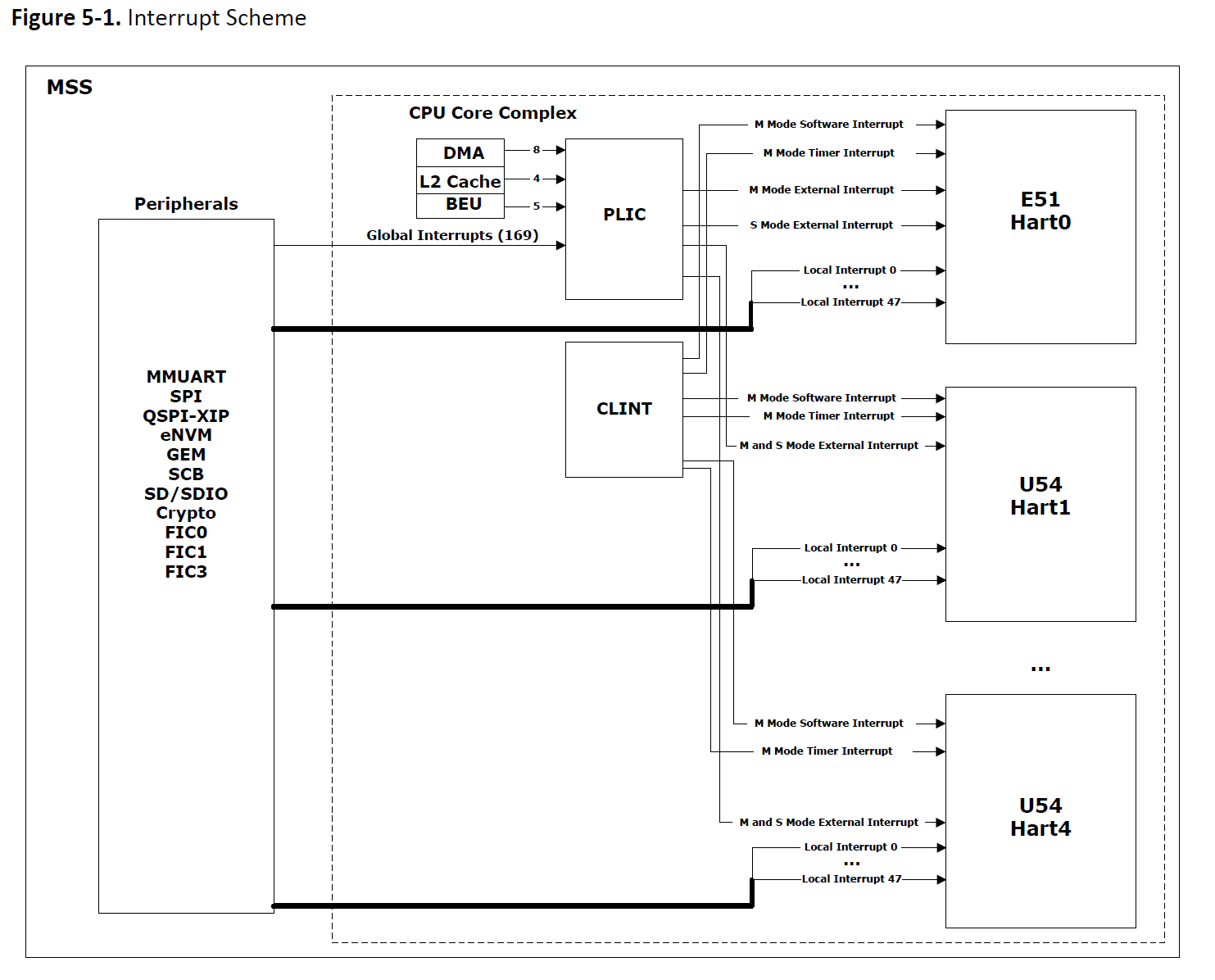
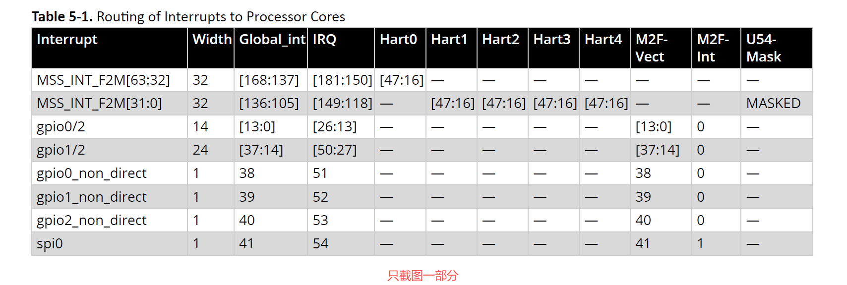
Table 5-1 lists the Local and Global interrupts implemented in the MSS.
For Example:
• The spi0 interrupt signal is a Global interrupt because it is not connected to any Hart as a Local
interrupt. This interrupt signal is connected to the PLIC.
• The mac0_int interrupt signal is a Local interrupt to Hart1 and Hart2. It can also be enabled as a
Global interrupt through the PLIC to Hart0, Hart3, and Hart4.
表5-1列出了MSS中实现的本地中断与全局中断。
例如:
• spi0中断信号属于全局中断,因其未作为本地中断连接至任何Hart。该中断信号连接至PLIC。
• mac0_int中断信号对Hart1与Hart2而言是本地中断,同时亦可通过PLIC配置为Hart0、Hart3及Hart4的全局中断。
The peripheral_ecc_error and peripheral_ecc_correct interrupts are driven by the EDAC_SR register.
To implementECC for peripherals, ECC interrupts are enabled individually by writing to the EDAC_INTEN_CR register.
ECC interrupts are cleared by writing to the EDAC_SR register.
ECC error count is available in EDAC_CNT_[peripheral] registers.
For more information about these registers, see the PFSOC_MSS_TOP_SYSREG in PolarFire SoC Device Register Map.
peripheral_ecc_error与peripheral_ecc_correct中断由EDAC_SR寄存器驱动。
为实现外设的ECC功能,需通过写EDAC_INTEN_CR寄存器单独启用各ECC中断。
ECC中断通过写EDAC_SR寄存器清除。
ECC错误计数信息存储于EDAC_CNT_[外设名称]寄存器中。
有关这些寄存器的详细信息,请参阅《PolarFire SoC器件寄存器映射》中的PFSOC_MSS_TOP_SYSREG章节。
To enable all Local interrupts on the U54_1 core, set the FAB_INTEN_U54_1 register using the SYSREG->FAB_INTEN_U54_1 = 0xffffffff;
instruction. This instruction enables all MSS_INT_F2M[31:0] interrupts to interrupt U54_1 directly.
Similarly, enable the Local interrupts on U54_2, U54_3, and U54_4 cores.
By default, all Local interrupts MSS_INT_F2M[63:32] are enabled on the E51 core.
若要启用U54_1核心上的所有本地中断,可通过执行指令SYSREG->FAB_INTEN_U54_1 = 0xffffffff;
设置FAB_INTEN_U54_1寄存器。该指令将使所有MSS_INT_F2M[31:0]中断信号直接向U54_1发起中断。
同理,可启用U54_2、U54_3及U54_4核心的本地中断。
默认情况下,E51核心已启用所有MSS_INT_F2M[63:32]本地中断。
5.1. Interrupt CSRs (Ask a Question)
5.1 中断控制状态寄存器(CSRs)(提问)
When a Hart receives an interrupt, the following events are executed:
当Hart接收到中断时,将执行以下事件:
1. The value of mstatus.MIE field is copied into mstatus.MPIE, then mstatus.MIE is cleared,effectively disabling interrupts.
1. mstatus.MIE字段的值被复制到mstatus.MPIE中,随后清空mstatus.MIE字段,从而有效禁用中断
2. The current value in the program counter (PC) is copied to the mepc register, and then PC is set to the value of mtvec. If vectored interrupts are enabled, PC is set to mtvec.BASE + 4 × exception code.
2. 程序计数器(PC)的当前值被复制到mepc寄存器,随后PC被设置为mtvec的值。若启用向量中断模式,则PC将被设置为mtvec.BASE + 4 × 异常代码
3. The Privilege mode prior to the interrupt is encoded in mstatus.MPP.
3. 中断发生前的特权模式被编码存储于mstatus.MPP字段
4. At this point, control is handed over to the software in the interrupt handler with interrupts disabled.
4. 此时中断处理程序以禁用中断的状态将控制权移交软件
Interrupts can be re-enabled by explicitly setting mstatus.MIE, or by executing the MRET instruction to exit the handler. When the MRET instruction is executed:
可通过显式设置mstatus.MIE字段或执行MRET指令退出处理程序来重新启用中断。当执行MRET指令时:
1. The Privilege mode is set to the value encoded in mstatus.MPP.
特权模式将被设置为mstatus.MPP字段编码的值
2. The value of mstatus.MPIE is copied to mstatus.MIE.
mstatus.MPIE的值被复制到mstatus.MIE字段
3. The PC is set to the value of mepc.
PC被设置为mepc的值
4. At this point, control is handed over to software.
此时控制权交还给软件
The Interrupt CSRs are described in the following sections. This document only describes the
implementation of interrupt CSRs specific to CPU Core Complex. For a complete description of
RISC-V interrupt behavior and how to access CSRs, see The RISC-V Instruction Set Manual, Volume II:
Privileged Architecture, Version 1.10.
后续章节将详细说明中断控制状态寄存器。本文档仅描述CPU核心复合体特有的中断CSR实现方案。关于RISC-V中断行为的完整说明及CSR访问方法,请参阅《RISC-V指令集手册第二卷:特权架构版本1.10》。
5.1.1. Machine STATUS Register (mstatus) (Ask a Question)
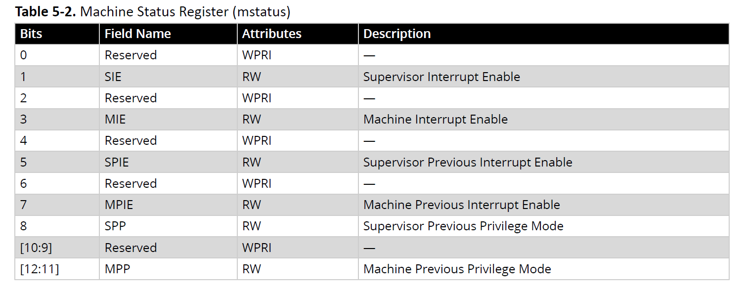
The mstatus register tracks and controls the current operating state of a Hart and tracks whether interrupts are enabled or not.
Interrupts are enabled by setting the MIE bit and by enabling the required individual interrupt in the mie register described in the next section.
The mstatus register description related to interrupts is provided in Table 5-2.
The mstatus register also contains fields unrelated to interrupts.
For a complete description of the mstatus register, see The RISC-V Instruction Set Manual, Volume II: Privileged Architecture, Version 1.10.
5.1.1 机器状态寄存器(mstatus)(提问)
mstatus寄存器用于跟踪和控制Hart的当前运行状态,并监测中断是否启用。
通过设置MIE位并在下一节所述的mie寄存器中启用所需的具体中断,可实现对中断的启用。
表5-2提供了mstatus寄存器中与中断相关的字段说明。
需注意的是,mstatus寄存器还包含与中断无关的其他字段。
关于mstatus寄存器的完整说明,请参阅《RISC-V指令集手册第二卷:特权架构版本1.10》。
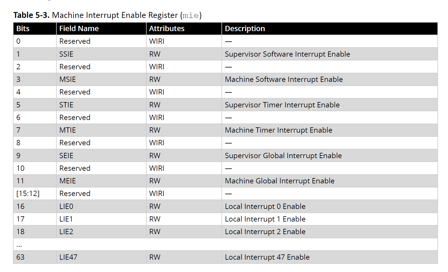
5.1.2. Machine Interrupt Enable Register (mie) (Ask a Question)
Individual interrupts are enabled by setting the appropriate bit in the mie register described in the
following table.
Table 5-3. Machine Interrupt Enable Register (mie)
5.1.2 机器中断使能寄存器(mie)(提问)
通过设置下表所述的mie寄存器中相应的位,可启用各个中断。
表5-3 机器中断使能寄存器(mie)
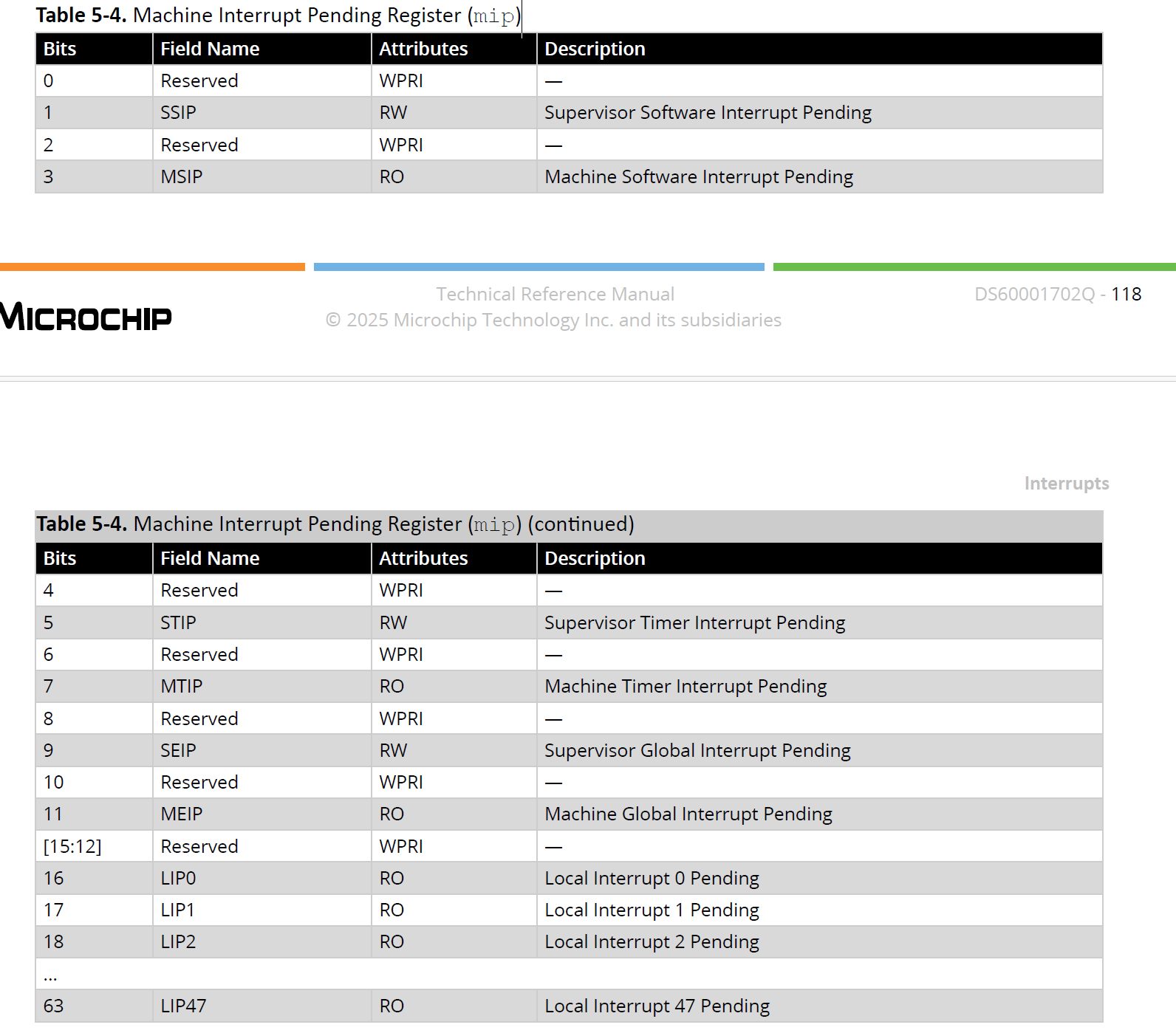
5.1.3. Machine Interrupt Pending Register (mip) (Ask a Question)
The machine interrupt pending (mip) register specifies interrupts which are currently pending.
Table 5-4. Machine Interrupt Pending Register (mip)
5.1.3 机器中断待处理寄存器(mip)(提问)
机器中断待处理(mip)寄存器用于指示目前处于待处理状态的中断。
表5-4 机器中断待处理寄存器(mip)
未完待续


 浙公网安备 33010602011771号