
利用二级RC滤波电路和PWM实现控制电压
利用RC滤波电路和PWM实现控制电压
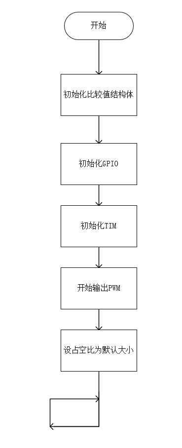
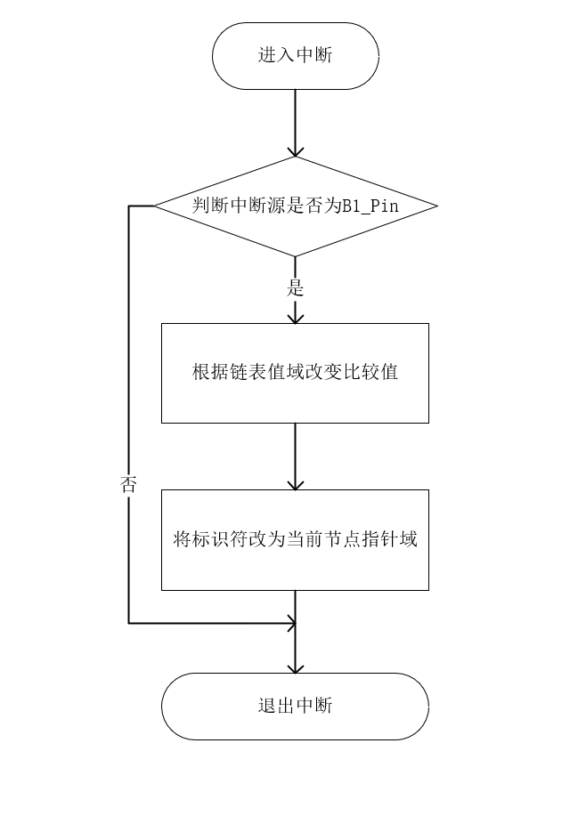
1、流程图
主函数
中断部分
2、初始化硬件
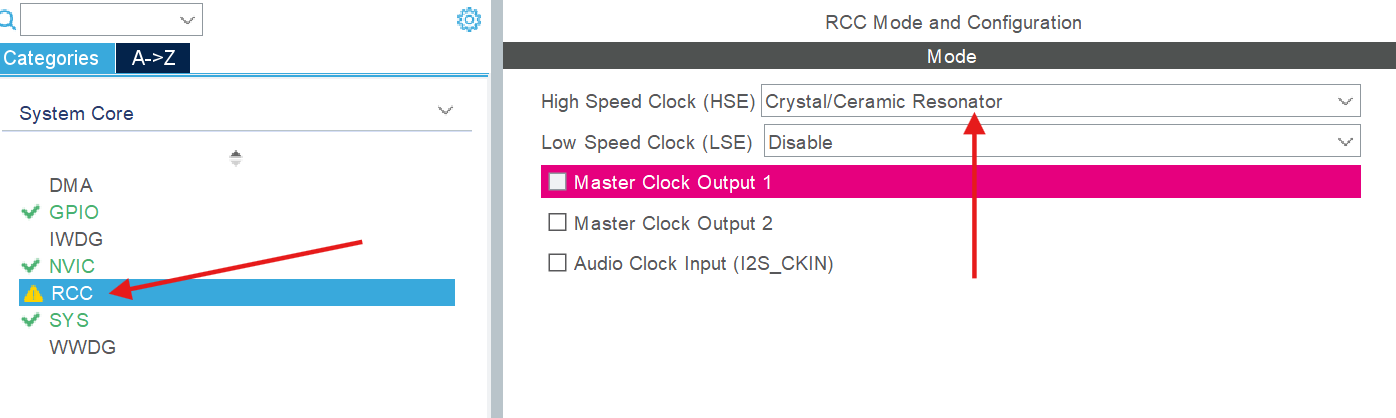
CubeMX部分
- 使能外部晶振
![img]()
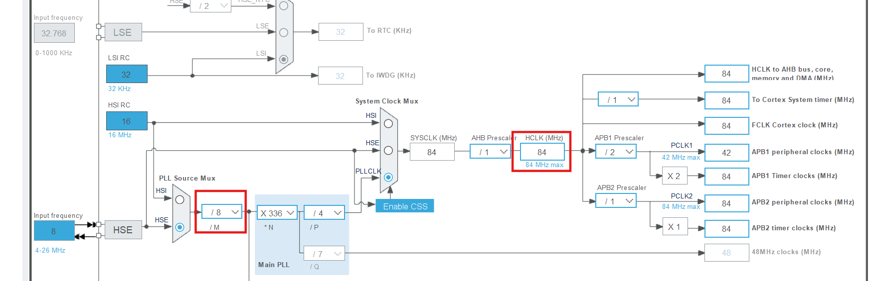
- 并按照如下方式配置时钟树
![img]()
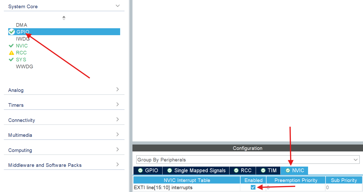
- 使能
GPIO的外部中断
![img]()
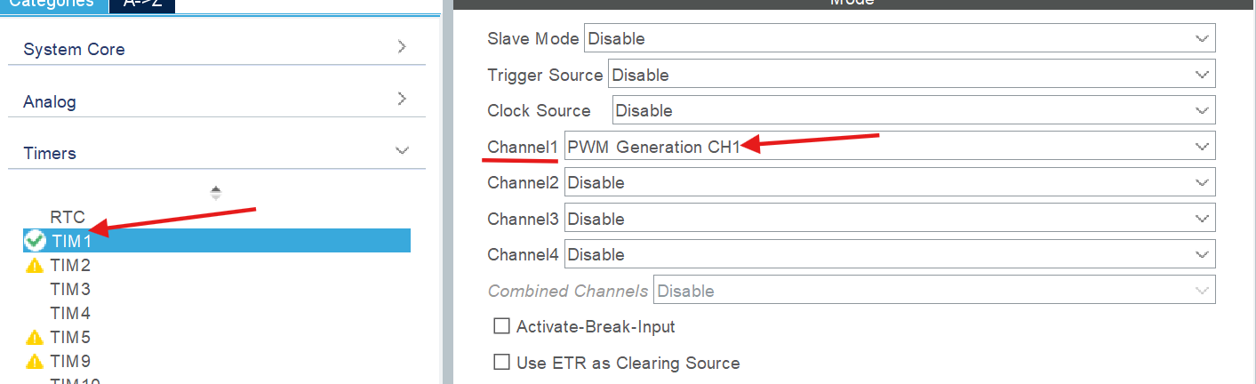
- 开启
TIM1,并开启通道1的"PWM生成模式"
![img]()
代码部分
(1)切换挡位
思路
- 使用环状链表来装载PWM的比较值,当按钮被按下后访问下一节点的比较值
链表结构
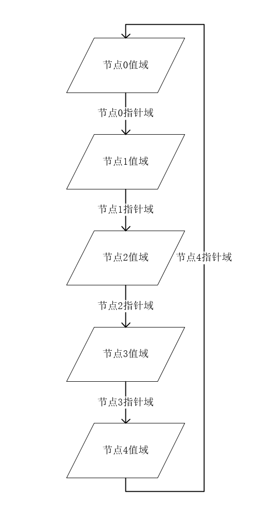
代码
- 在
main.c中声明标识符flag以及结构体数组Nodes
/* USER CODE BEGIN 0 */
struct Comparison{
	int Value;
	int Next;
}Nodes[5];
int flag = 0;//标识符为全局变量,因此默认为0,不需要初始化
- 在主函数内对结构体进行初始化
  /* USER CODE BEGIN 1 */
	Nodes[0].Next = 1;
	Nodes[0].Value = 2200;
	Nodes[1].Next = 2;
	Nodes[1].Value = 2700;
	Nodes[2].Next = 3;
	Nodes[2].Value = 3200;
	Nodes[3].Next = 4;
	Nodes[3].Value = 3700;
	Nodes[4].Next = 0;
	Nodes[4].Value = 4200 - 1;
  /* USER CODE END 1 */
(2) 输出PWM
- 在主函数内写入以下内容
  /* USER CODE BEGIN 2 */
	HAL_TIM_PWM_Start (&htim1,TIM_CHANNEL_1);
	__HAL_TIM_SetCompare(&htim1, TIM_CHANNEL_1, Nodes[flag].Value);
  /* USER CODE END 2 */
电路部分
- 材料:10 \(\Omega\) 色环电阻4个 3.3\(\mu F\)电解电容2个,导线若干,面包板1块
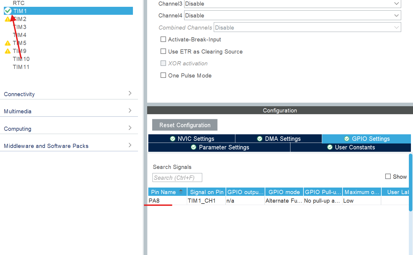
(1)寻找管脚
- 根据
CubeMX中的信息,已知PWM从PA8引脚输出
![img]()
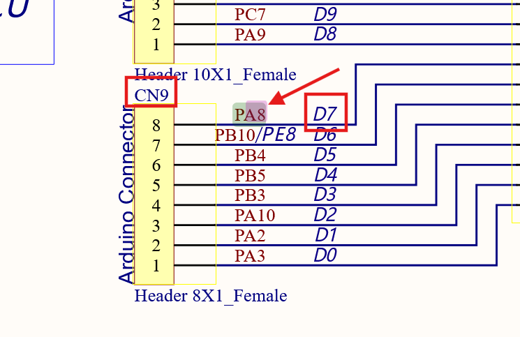
- 由原理图可知,
PA8位于CN9的D7位置
![img]()
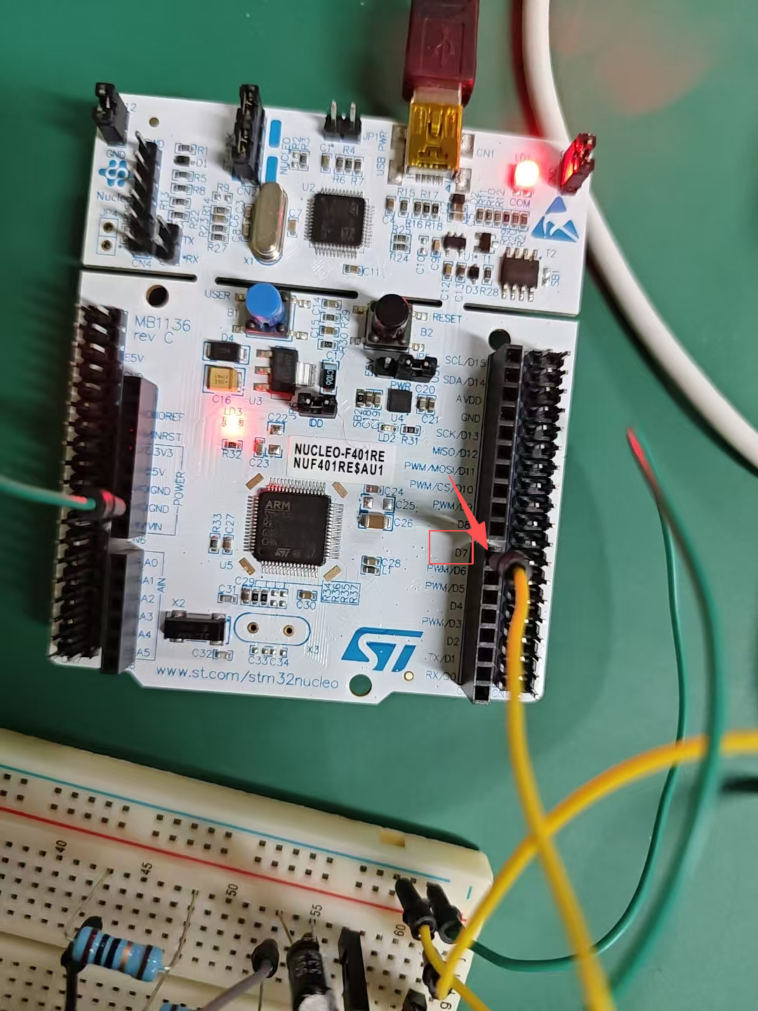
- 根据原理图编号,定位到开发板相应实际位置
![img]()
(2)搭建二级RC滤波电路
- 根据如下电路图,搭建滤波电路
![img]()
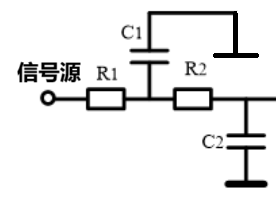
由于
PWM频率依旧为20kHz,具体选择器件的过程就略过了,详情可看这给帖子利用脉冲位宽调制技术和一级滤波电路实现正弦波输出
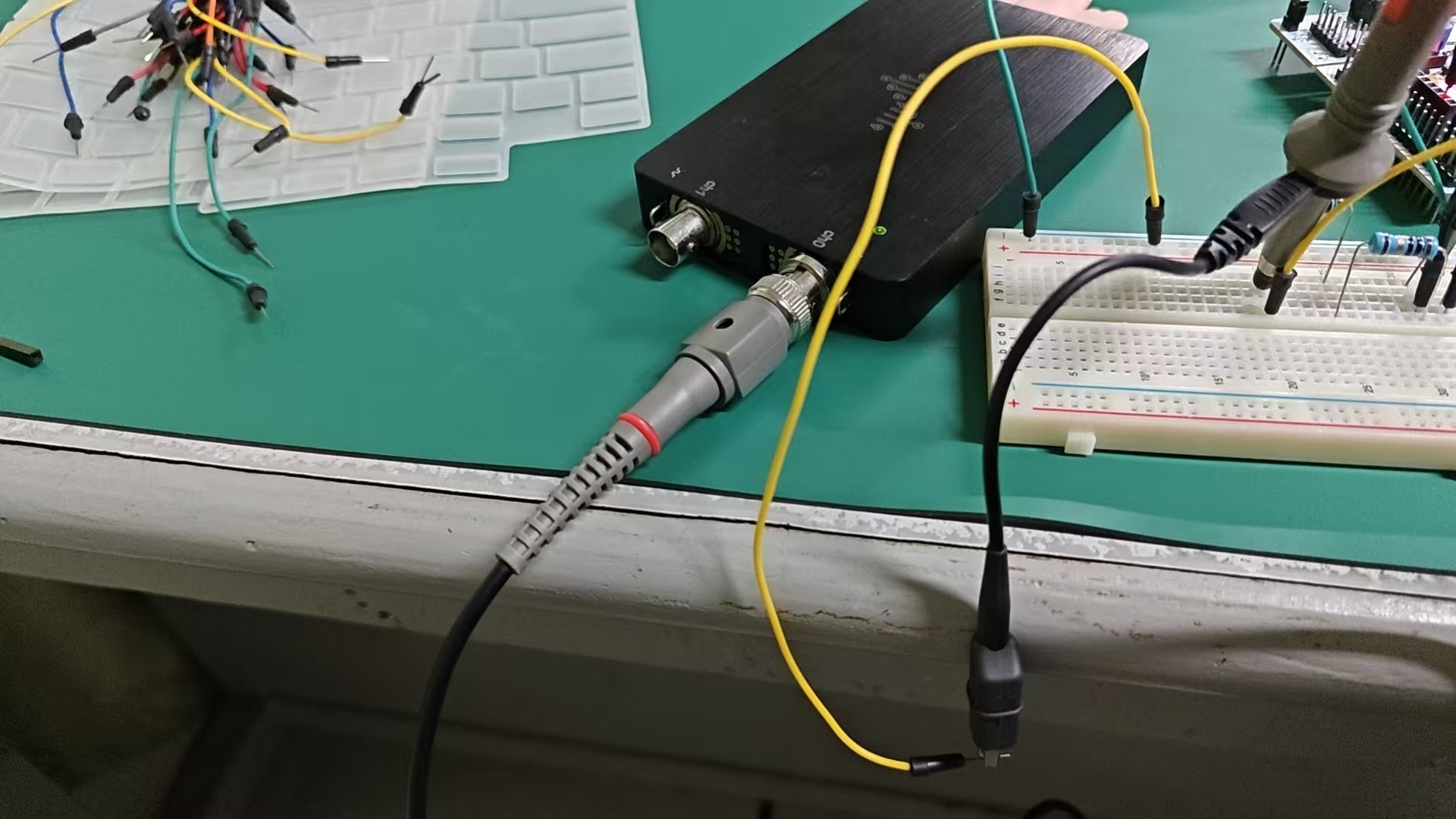
- 按照计算结果和器件搭建电路
![img]()

3、验证PWM
- 在写中断处理部分前,可先输出固定比较值的
PWM,并采样观测频率是否符合预期
代码部分
__HAL_TIM_SetCompare(&htim1, TIM_CHANNEL_1, 2200);
  /* USER CODE END 2 */
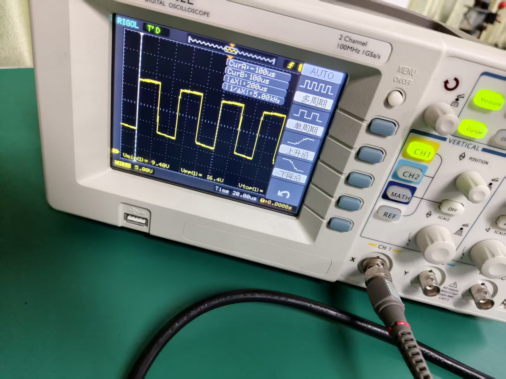
- 验证结果
![img]()
![img]()
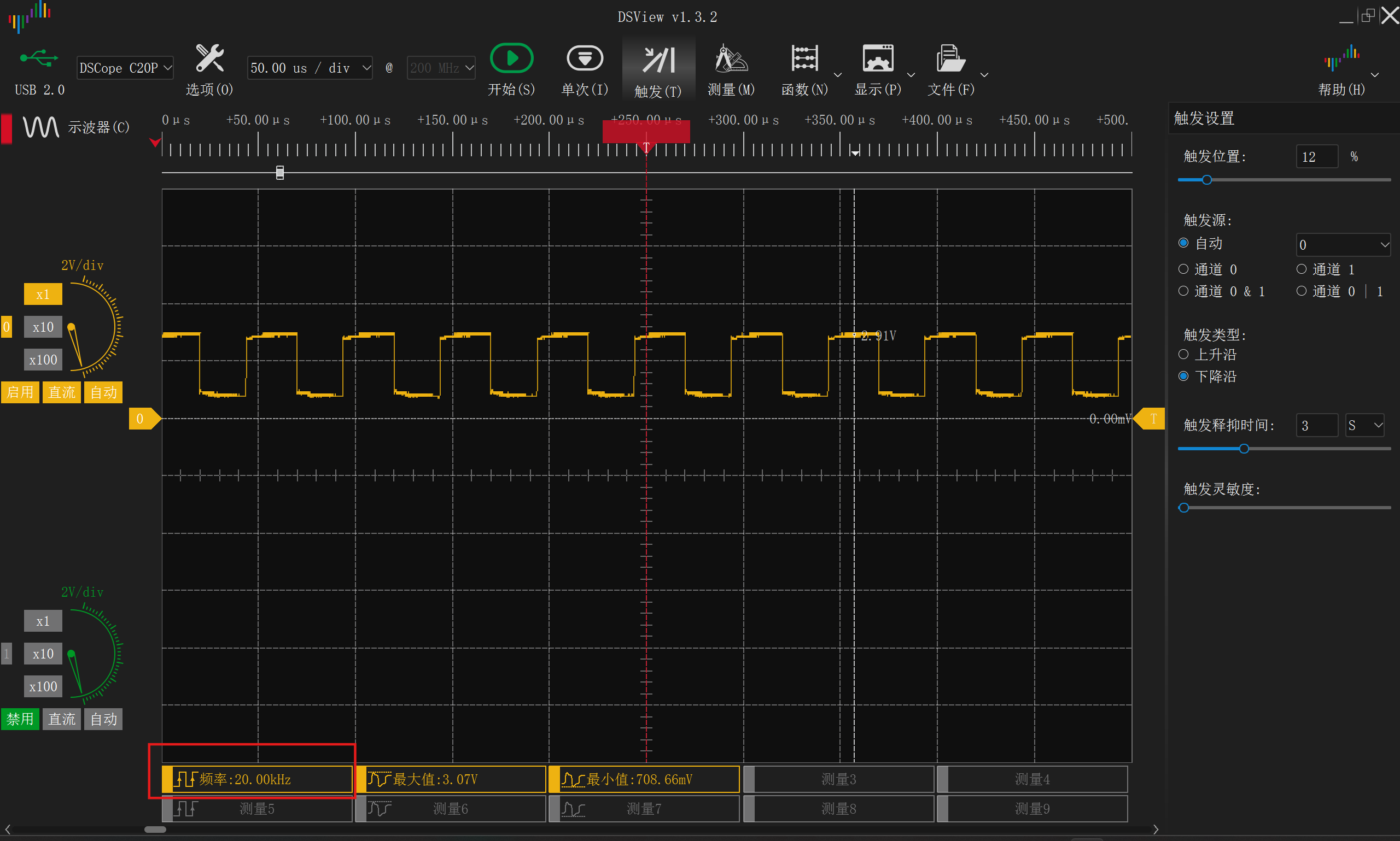
输出频率为20kHz,符合预期
4、写入代码
中断部分
- 根据链表处思路,写入以下内容
void HAL_GPIO_EXTI_Callback(uint16_t GPIO_Pin){
	if(GPIO_Pin == B1_Pin){//判断中断来源是否为按钮
		__HAL_TIM_SetCompare(&htim1, TIM_CHANNEL_1, Nodes[Nodes[flag].Next].Value);//将比较值设为下一节点值域
		flag = Nodes[flag].Next;//将标识符移动至下一指针域
	}
}
/* USER CODE END 0 */
5、实验效果
最终效果
- 每按下一次蓝色按钮,音量会增加,当音量最大时,再次按下会转变为最小音量
信号波形
PWM方波信号源
![img]()
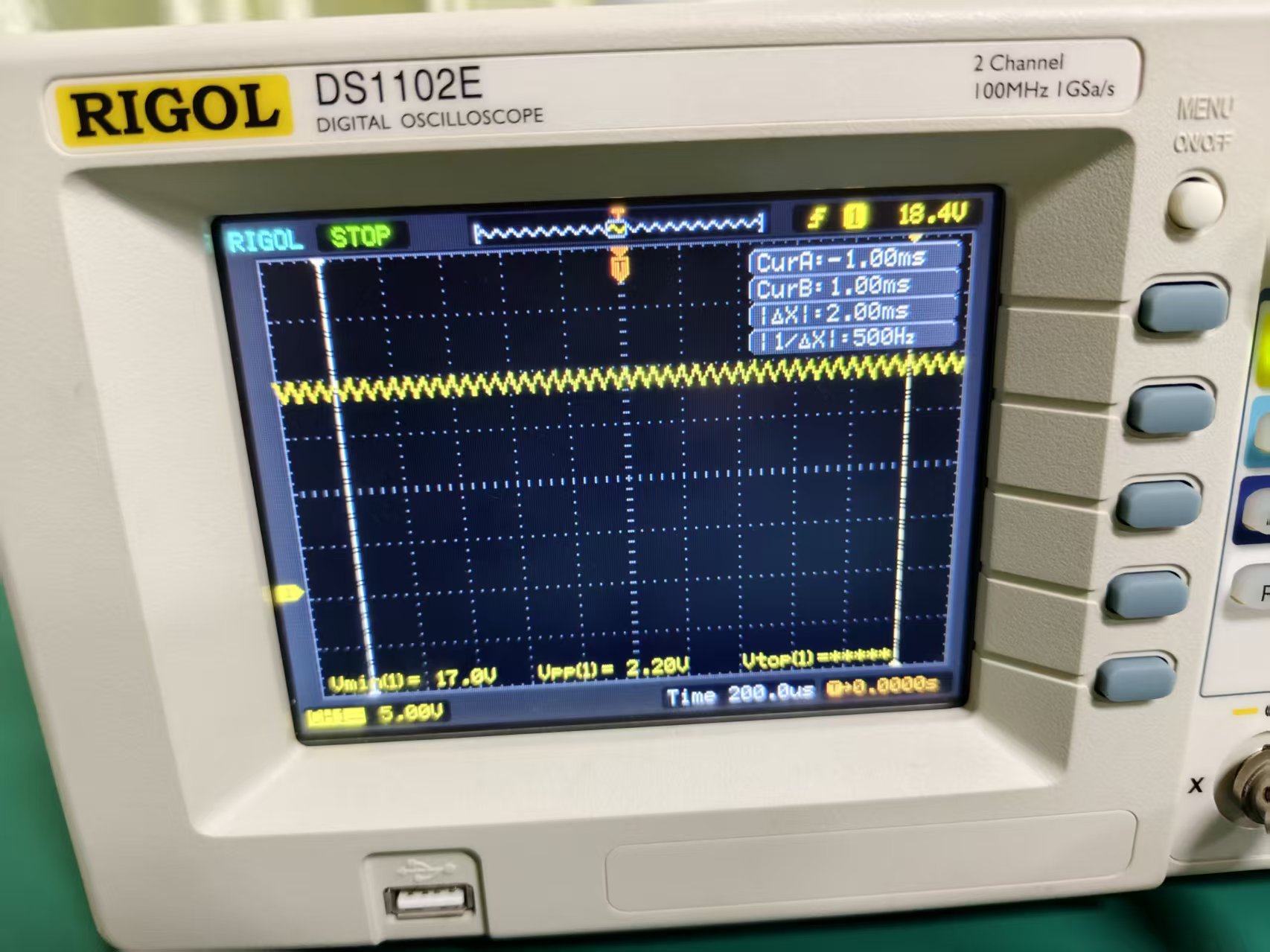
- 一级滤波后信号
![img]()
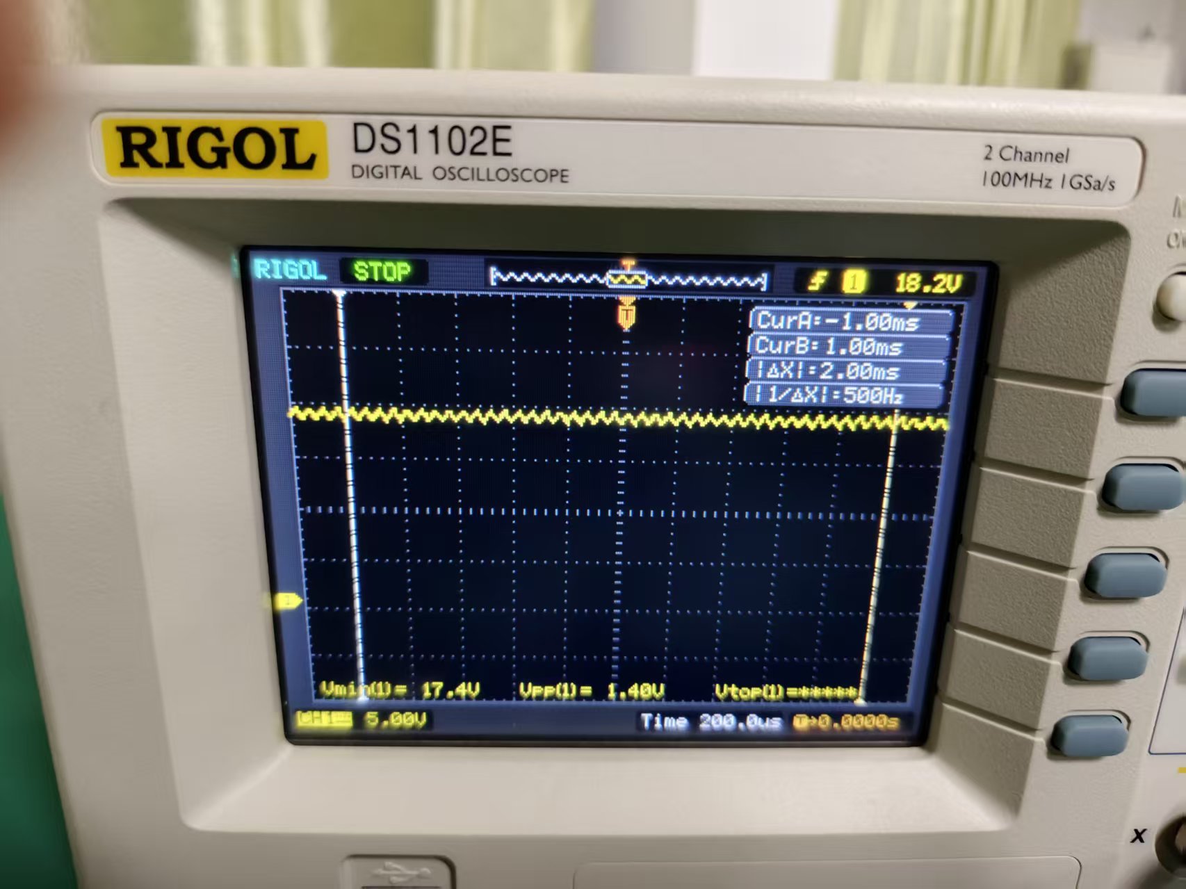
- 二级滤波后信号
![img]()
6、代码清单
main.c
/* USER CODE BEGIN Header */
/**
  ******************************************************************************
  * @file           : main.c
  * @brief          : Main program body
  ******************************************************************************
  * @attention
  *
  * Copyright (c) 2025 STMicroelectronics.
  * All rights reserved.
  *
  * This software is licensed under terms that can be found in the LICENSE file
  * in the root directory of this software component.
  * If no LICENSE file comes with this software, it is provided AS-IS.
  *
  ******************************************************************************
  */
/* USER CODE END Header */
/* Includes ------------------------------------------------------------------*/
#include "main.h"
#include "tim.h"
#include "gpio.h"

/* Private includes ----------------------------------------------------------*/
/* USER CODE BEGIN Includes */

/* USER CODE END Includes */

/* Private typedef -----------------------------------------------------------*/
/* USER CODE BEGIN PTD */

/* USER CODE END PTD */

/* Private define ------------------------------------------------------------*/
/* USER CODE BEGIN PD */

/* USER CODE END PD */

/* Private macro -------------------------------------------------------------*/
/* USER CODE BEGIN PM */

/* USER CODE END PM */

/* Private variables ---------------------------------------------------------*/

/* USER CODE BEGIN PV */

/* USER CODE END PV */

/* Private function prototypes -----------------------------------------------*/
void SystemClock_Config(void);
/* USER CODE BEGIN PFP */

/* USER CODE END PFP */

/* Private user code ---------------------------------------------------------*/
/* USER CODE BEGIN 0 */
struct Comparison{//The comparion nodes of PWM
	int Value;
	int Next;
}Nodes[5];
int flag = 0;
void HAL_GPIO_EXTI_Callback(uint16_t GPIO_Pin){
	if(GPIO_Pin == B1_Pin){//Pend if the interrupt source is come from B1_Pin
		__HAL_TIM_SetCompare(&htim1, TIM_CHANNEL_1, Nodes[Nodes[flag].Next].Value);
		flag = Nodes[flag].Next;
	}
}
/* USER CODE END 0 */

/**
  * @brief  The application entry point.
  * @retval int
  */
int main(void)
{

  /* USER CODE BEGIN 1 */
	Nodes[0].Next = 1;
	Nodes[0].Value = 2200;
	Nodes[1].Next = 2;
	Nodes[1].Value = 2700;
	Nodes[2].Next = 3;
	Nodes[2].Value = 3200;
	Nodes[3].Next = 4;
	Nodes[3].Value = 3700;
	Nodes[4].Next = 0;
	Nodes[4].Value = 4200 - 1;
  /* USER CODE END 1 */

  /* MCU Configuration--------------------------------------------------------*/

  /* Reset of all peripherals, Initializes the Flash interface and the Systick. */
  HAL_Init();

  /* USER CODE BEGIN Init */

  /* USER CODE END Init */

  /* Configure the system clock */
  SystemClock_Config();

  /* USER CODE BEGIN SysInit */

  /* USER CODE END SysInit */

  /* Initialize all configured peripherals */
  MX_GPIO_Init();
  MX_TIM1_Init();
  /* USER CODE BEGIN 2 */
	HAL_TIM_PWM_Start (&htim1,TIM_CHANNEL_1);
	__HAL_TIM_SetCompare(&htim1, TIM_CHANNEL_1, Nodes[flag].Value);
  /* USER CODE END 2 */

  /* Infinite loop */
  /* USER CODE BEGIN WHILE */
  while (1)
  {
    /* USER CODE END WHILE */

    /* USER CODE BEGIN 3 */
  }
  /* USER CODE END 3 */
}

/**
  * @brief System Clock Configuration
  * @retval None
  */
void SystemClock_Config(void)
{
  RCC_OscInitTypeDef RCC_OscInitStruct = {0};
  RCC_ClkInitTypeDef RCC_ClkInitStruct = {0};

  /** Configure the main internal regulator output voltage
  */
  __HAL_RCC_PWR_CLK_ENABLE();
  __HAL_PWR_VOLTAGESCALING_CONFIG(PWR_REGULATOR_VOLTAGE_SCALE2);

  /** Initializes the RCC Oscillators according to the specified parameters
  * in the RCC_OscInitTypeDef structure.
  */
  RCC_OscInitStruct.OscillatorType = RCC_OSCILLATORTYPE_HSE;
  RCC_OscInitStruct.HSEState = RCC_HSE_ON;
  RCC_OscInitStruct.PLL.PLLState = RCC_PLL_ON;
  RCC_OscInitStruct.PLL.PLLSource = RCC_PLLSOURCE_HSE;
  RCC_OscInitStruct.PLL.PLLM = 8;
  RCC_OscInitStruct.PLL.PLLN = 336;
  RCC_OscInitStruct.PLL.PLLP = RCC_PLLP_DIV4;
  RCC_OscInitStruct.PLL.PLLQ = 7;
  if (HAL_RCC_OscConfig(&RCC_OscInitStruct) != HAL_OK)
  {
    Error_Handler();
  }

  /** Initializes the CPU, AHB and APB buses clocks
  */
  RCC_ClkInitStruct.ClockType = RCC_CLOCKTYPE_HCLK|RCC_CLOCKTYPE_SYSCLK
                              |RCC_CLOCKTYPE_PCLK1|RCC_CLOCKTYPE_PCLK2;
  RCC_ClkInitStruct.SYSCLKSource = RCC_SYSCLKSOURCE_PLLCLK;
  RCC_ClkInitStruct.AHBCLKDivider = RCC_SYSCLK_DIV1;
  RCC_ClkInitStruct.APB1CLKDivider = RCC_HCLK_DIV2;
  RCC_ClkInitStruct.APB2CLKDivider = RCC_HCLK_DIV1;

  if (HAL_RCC_ClockConfig(&RCC_ClkInitStruct, FLASH_LATENCY_2) != HAL_OK)
  {
    Error_Handler();
  }
}

/* USER CODE BEGIN 4 */

/* USER CODE END 4 */

/**
  * @brief  This function is executed in case of error occurrence.
  * @retval None
  */
void Error_Handler(void)
{
  /* USER CODE BEGIN Error_Handler_Debug */
  /* User can add his own implementation to report the HAL error return state */
  __disable_irq();
  while (1)
  {
  }
  /* USER CODE END Error_Handler_Debug */
}
#ifdef USE_FULL_ASSERT
/**
  * @brief  Reports the name of the source file and the source line number
  *         where the assert_param error has occurred.
  * @param  file: pointer to the source file name
  * @param  line: assert_param error line source number
  * @retval None
  */
void assert_failed(uint8_t *file, uint32_t line)
{
  /* USER CODE BEGIN 6 */
  /* User can add his own implementation to report the file name and line number,
     ex: printf("Wrong parameters value: file %s on line %d\r\n", file, line) */
  /* USER CODE END 6 */
}
#endif /* USE_FULL_ASSERT */

 浙公网安备 33010602011771号