nju实验六 移位寄存器及桶形移位器
 本实验将学习常用的移位寄存器的设计,并实现在移位指令中需要用到的桶形移位器。
算术移位和逻辑移位寄存器
module shift_register_8bit (
    input clk,              // 时钟信号
    input rst,              // 异步复位
    input [2:0] mode,       // 工作模式选择
    input [7:0] data_in,    // 并行输入数据(用于置数模式)
    input serial_in,        // 串行输入数据
    input shift_in,         // 移位输入(用于算术/逻辑移位)
    output reg [7:0] data_out // 并行输出
);

    // 寄存器核心
    reg [7:0] reg_data;

    always @(posedge clk or posedge rst) begin
        if (rst) begin
            reg_data <= 8'b0;  // 异步复位
        end else begin
            case(mode)
                3'b000: reg_data <= 8'b0;          // 清零
                3'b001: reg_data <= data_in;       // 置数
                3'b010: reg_data <= {shift_in, reg_data[7:1]}; // 逻辑右移
                3'b011: reg_data <= {reg_data[6:0], shift_in}; // 逻辑左移
                3'b100: reg_data <= {reg_data[7], reg_data[7:1]}; // 算术右移
                3'b101: reg_data <= {reg_data[6:0], serial_in}; // 左端串行输入
                3'b110: reg_data <= {reg_data[0], reg_data[7:1]}; // 循环右移
                3'b111: reg_data <= {reg_data[6:0], reg_data[7]}; // 循环左移
                default: reg_data <= reg_data;     // 保持
            endcase
        end
    end

    // 并行输出
    always @(*) begin
        data_out = reg_data;
    end

endmodule
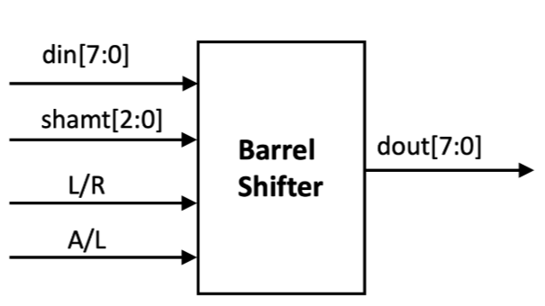
RV32I指令集的32位移位
module shifter_32 (
    input [31:0] data_in,    // 输入数据
    input [4:0]  shamt,      // 移位位数
    input [1:0]  shift_op,   // 移位类型: 00=SLL, 01=SRL, 10=SRA
    output [31:0] data_out   // 移位结果
);
    reg [31:0] shifted;

    always @(*) begin
        case(shift_op)
            2'b00: shifted = data_in << shamt;       // SLL
            2'b01: shifted = data_in >> shamt;       // SRL
            2'b10: shifted = $signed(data_in) >>> shamt; // SRA
            default: shifted = data_in;              // 无移位
        endcase
    end

    assign data_out = shifted;
endmodule
8位LFSR伪随机数发生器
.
├── constr
│ └── top.nxdc
├── csrc
│ └── test_our.cpp
├── Makefile
├── vsrc
│ └── top.v
├── top.v
├── vlt_dump.vcd
├── test_our.cpp
├── obj_dir
└── dump.vcd
├── constr
└── top.nxdc
top=top

button BTNL

rst_n BTNC

leds (LD7, LD6, LD5, LD4, LD3, LD2, LD1, LD0)
hex0 (SEG0A, SEG0B, SEG0C, SEG0D, SEG0E, SEG0F, SEG0G, DEC0P)
hex1 (SEG1A, SEG1B, SEG1C, SEG1D, SEG1E, SEG1F, SEG1G, DEC1P)
├── csrc
└── test_our.cpp
#include<nvboard.h>
#include<Vtop.h>

static TOP_NAME dut;

void nvboard_bind_all_pins(TOP_NAME* top);

static void single_cycle(){
    dut.eval();
}

int main(){
	nvboard_bind_all_pins(&dut);
	nvboard_init();

	while(1){
		nvboard_update();
		single_cycle();
	}

}
├── test_our.cpp
#include "verilated.h"
#include "verilated_vcd_c.h"
#include "obj_dir/Vtop.h"

VerilatedContext* contextp = NULL;
VerilatedVcdC* tfp = NULL;

#define MAX_SIM_TIME 20
int sim_time = 0;

static Vtop* top;

void step_and_dump_wave(){
  top->eval();
  contextp->timeInc(1);
  tfp->dump(contextp->time());
}
void sim_init(){
  contextp = new VerilatedContext;
  tfp = new VerilatedVcdC;
  top = new Vtop;
  contextp->traceEverOn(true);
  top->trace(tfp, 0);
  tfp->open("dump.vcd");
}

void sim_exit(){
  step_and_dump_wave();
  tfp->close();
}

int main() {
  sim_init();

  while (sim_time < MAX_SIM_TIME) {
  	top->button ^=1;
  	step_and_dump_wave();
  	sim_time ++;
  }

  sim_exit();
}
├── vsrc
└── top.v
module top (
    input button,           // KEY0按钮输入
    input rst_n,            // 复位信号(低电平有效)
    output [7:0] hex0,      // 低位七段数码管(直接输出编码)
    output [7:0] hex1,      // 高位七段数码管
    output [7:0] leds       // LED显示当前状态
);

    // 8位LFSR寄存器(初始种子为00000001)
    reg [7:0] lfsr = 8'b00000001;


    // 反馈位计算:x4 XOR x3 XOR x2 XOR x0
    wire feedback = lfsr[4] ^ lfsr[3] ^ lfsr[2] ^ lfsr[0];

    // LFSR更新逻辑
    always @(negedge button or posedge rst_n) begin
    	if (rst_n) lfsr <= 8'b00000001;
    	else begin
            lfsr <= {feedback, lfsr[7:1]};  // 右移并插入反馈位
            if (lfsr == 8'b0) lfsr <= 8'b00000001; // 防全零锁定
        end
    end

    // 数码管显示模块(根据您提供的编码表)
    seg7_decoder seg0 (.bin(lfsr[3:0]), .seg(hex0));
    seg7_decoder seg1 (.bin(lfsr[7:4]), .seg(hex1));

    // LED显示当前状态
    assign leds = lfsr;

endmodule

// 根据您提供的编码表实现的七段译码器
module seg7_decoder (
    input [3:0] bin,
    output reg [7:0] seg
);
always @(*) begin
    case(bin)
        4'h0: seg = 8'b00000011; // 0
        4'h1: seg = 8'b10011111; // 1
        4'h2: seg = 8'b00100101; // 2
        4'h3: seg = 8'b00001101; // 3
        4'h4: seg = 8'b10011001; // 4
        4'h5: seg = 8'b01001001; // 5
        4'h6: seg = 8'b01000001; // 6
        4'h7: seg = 8'b00011111; // 7
        4'h8: seg = 8'b00000001; // 8
        4'h9: seg = 8'b00001001; // 9
        4'hA: seg = 8'b00010001; // A(自定义)
        4'hB: seg = 8'b11000001; // B(自定义)
        4'hC: seg = 8'b01100011; // C(自定义)
        4'hD: seg = 8'b10000101; // D(自定义)
        4'hE: seg = 8'b01100001; // E(自定义)
        4'hF: seg = 8'b01110001; // F(自定义)
        default: seg = 8'b11111111; // 全灭
    endcase
end
endmodule
├── top.v
module top (
    input button,           // KEY0按钮输入
    output [7:0] leds       // LED显示当前状态
);

    // 8位LFSR寄存器(初始种子为00000001)
    reg [7:0] lfsr = 8'b00000001;

    // 反馈位计算:x4 XOR x3 XOR x2 XOR x0
    wire feedback = lfsr[4] ^ lfsr[3] ^ lfsr[2] ^ lfsr[0];

    // LFSR更新逻辑
    always @(negedge button ) begin
        lfsr <= {feedback, lfsr[7:1]};  // 右移并插入反馈位
        if (lfsr == 8'b0) lfsr <= 8'b00000001; // 防全零锁定
    end
    // LED显示当前状态
    assign leds = lfsr;

endmodule
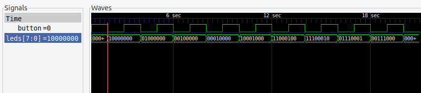
波形仿真
(1)编译
verilator -Wall --trace -cc top.v --exe main.cpp
(2)生成可执行文件
 make -C obj_dir -f Vtop.mk Vtop
(3)生成波形
./obj_dir/Vtop
(4)查看波形
gtkwave dump.vcd
接入NVBoard
make
cd build
./top

 浙公网安备 33010602011771号