(笔记)自定义指令CRC Custom Instruction实例学习
环境
QII9.0 + NiosII9.0 IDE
1、手册中的步骤
Implementing Custom Instruction Hardware in SOPC Builder
Open the Component Editor
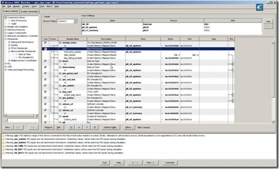
1. Open the SOPC Builder system.
2. On the SOPC Builder System Contents tab, double-click cpu.
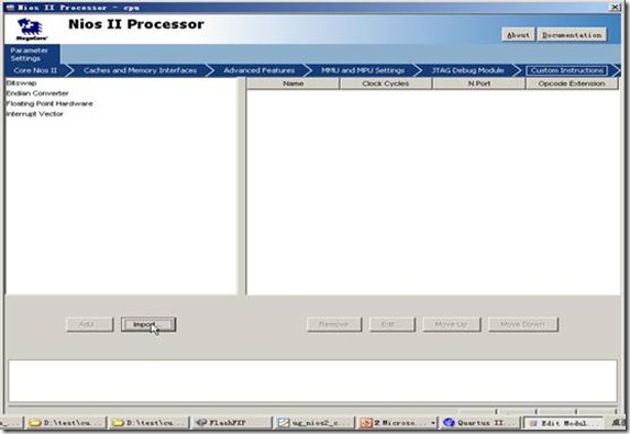
The Nios II Processor configuration wizard appears.
3. On the Parameter Settings page, click the Custom Instructions tab.
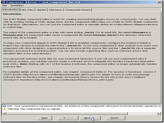
4. Click Import. The component editor appears, displaying the Introduction tab.
Add the Synthesis HDL File
1. Click Next to display the HDL Files tab.
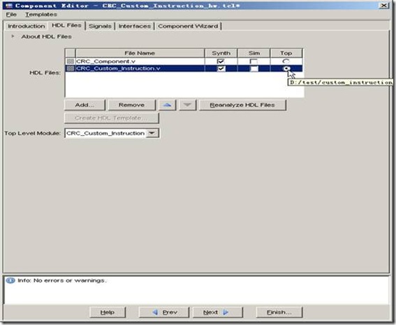
2. Click Add.
3. Browse to the directory containing the hardware description language (HDL) file(s), select the files needed, and click Open. The files to be added in this demonstration are
CRC_Custom_Instruction.v and CRC_Component.v located in crc_hw directory.
4. Turn on the Synth parameter for each of the HDL files added. This is to indicate that these files have synthesis equivalents. Both HDL files imported in this demonstration have synthesis equivalents
5. Turn on the Top parameter to indicate where the top-level HDL file is. The top-level HDL file for this demonstration is CRC_Custom_Instruction.v.
6. Click Top Level Module and select the name of the top-level module of your custom instruction logic. The top-level module of the design in this demonstration is CRC_Custom_Instruction.
Configure the Custom Instruction Signal Type
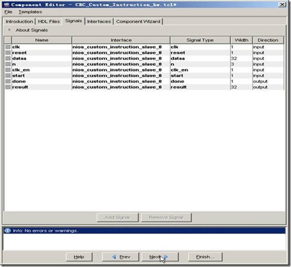
1.Click Next to display the Signals tab. There are several ports (signals) listed.
2. For every port listed, carry out the following steps:
a. Select the port.
b. In the Interface drop-down list, select the interface name you wish to assign the port with,
c. In the Signal Type drop-down list, select the signal type corresponding to the port name. For example, if the custom instruction hardware presents the result on a port named output, you set the Signal Type to result.
Set Up Custom Instruction Interfaces
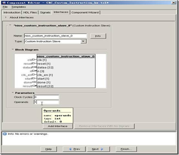
1. Click Next to display the Interfaces tab. The default interface type displayed is Custom Instruction Slave.
2. Rename the interface by typing the desired name in the Name field. You can use the default name if you do not intend to change the
name.
3. Set the Operands parameter value to the number of operands used for the custom instruction. The custom instruction used in this demonstration has only one operand, so set the Operands parameter to one.
4. If you are using fixed multi-cycle type custom instruction, set the Clock Cycles parameter value to the number of clock cycles your custom instruction logic needs. The design in this demonstration is of variable multi-cycle type, so set the Clock Cycles parameter to zero.
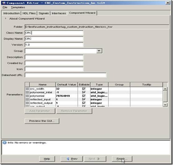
Set the Component Wizard Details
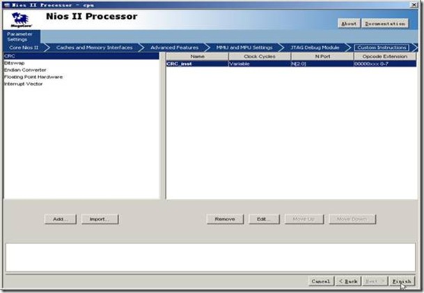
Save and Add the Custom Instruction
Generate the SOPC Builder System and Compile in the Quartus II Software
Accessing the Custom Instruction from Software
二、所遇到的问题
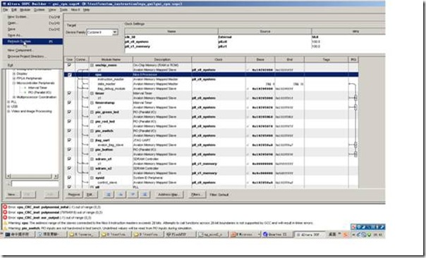
HardWare:
1.out of range
2.Component not found
3.parameter is a std_logic_vector but its width is not known
非常莫名奇妙,这些问题本不该有,不明白是不是版本的问题
解决方法,把代码中带parameter的部分都改成固定的不带参数的代码
SoftWare
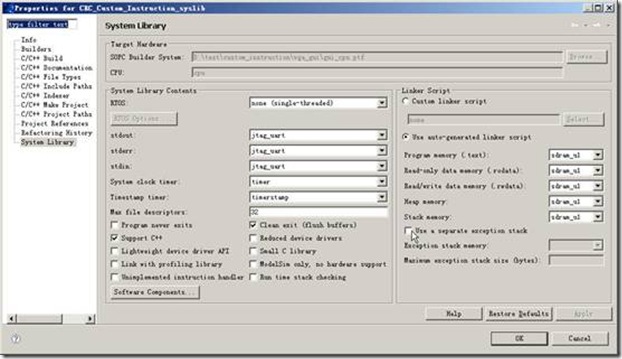
1.对syslib的设置
主要是对memory的设置,默认的on-chip容量不够,还有对Timestamp Timer的设置,软件中需用来测试时间性能
2.软件代码的修改
改宏名字CRC_CI_MACRO,与新生成的代码相同
Crc_main.c中#define MEMORY_DEVICE_SIZE DDR_SDRAM_0 ##_SPAN
改成具体的memory大小
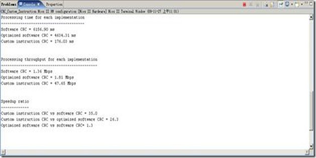
大概至此,编译便没有错误了。(但执行结果,软硬件有出入,不过这并不是我最关心的)



 浙公网安备 33010602011771号