IfcMaterialLayerSetUsage
IfcMaterialLayerSetUsage
实体定义
IfcMaterialLayerSetUsage根据其相对于关联图元几何图形的位置和方向来确定IfcMaterialLayoutSet的用途。材料层组的位置应与建筑构件的几何形状相兼容(即,材料层应适合构件的几何形状)。确保兼容性的规则取决于建筑图元的类型。
示例对于形状表示为SweptSolid的空心砖墙,IfcMaterialLayerSet。总厚度应等于壁厚。此外,偏离基准线应与IfcWallStandardCase的两个形状表示之间的确切位置相匹配,即IfcShapeResentation的Representation,其RepresentationIdentifier=“Axis”和RepresentationalIdentifier=”Body“。
注:模型视图定义或实施者协议可能会提供更多关于建筑图元几何图形和材质图层集使用之间匹配的说明。
IfcMaterialLayerSetUsage始终指定给单个引用对象(并且仅指定给IfcElement的相关子类型)。但是,ForLayerSet引用的IfcMaterialLayerSet可以在多个引用对象之间共享。如果元素类型可用(换句话说,存在IfcElementType的相关子类型的实例),则可以将IfcMaterialLayerSet分配给该元素类型。IfcElement的子类型和IfcMaterialLayerSetUsage之间的分配由IfcRelAssociatesSmaterial处理。
属性使用定义
IfcMaterialLayerSetUsage主要用于与具有恒定厚度的平面建筑构件相关联。随着对LayerSetDirection的解释达成进一步协议,只要材料层厚度不变,该用法也可以扩展到其他情况,例如弯曲的建筑构件。
通常,一个元件可以在其任何一个主方向上分层,由其x、y或z轴表示。每种特定类型的建筑图元的几何图形使用定义将确定适用的LayerSetDirection。
以下示例说明如何在不同情况下使用IfcMaterialLayerSetUsage属性(LayerSetDirection、DirectionSense、OffsetFromReferenceLine)。规范性材料使用定义在每个元素处都有文件记录(应如何使用这些定义)。
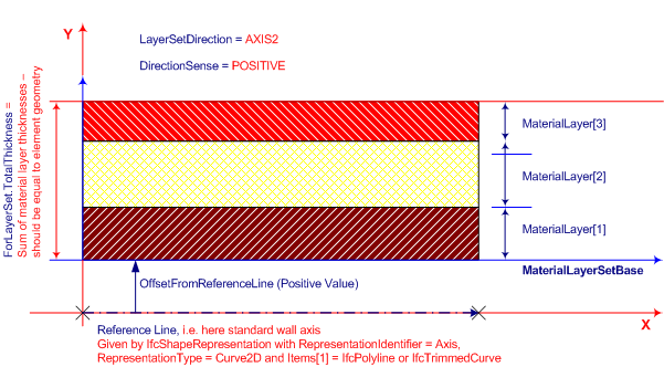
下图显示了与墙轴线对齐的IfcMaterialLayerSetUsage的使用示例。
示例对于具有拉伸几何表示(垂直拉伸)的标准墙,图层集方向将垂直于拉伸方向,并且可以从墙轴的方向导出。使用DirectionSense(在本例中为正),将从右到左或从左到右连续指定各个IfcMaterialLayers。对于弯曲墙,“表示墙厚度的方向”可以从墙轴线的方向导出,并且它将保持垂直于墙路径。DirectionSense同样适用。
注:根据IfcWallStandardCase材质使用定义,IfcWallStandard的LayerSetDirection始终为AXIS2(即沿y轴),如本例所示。
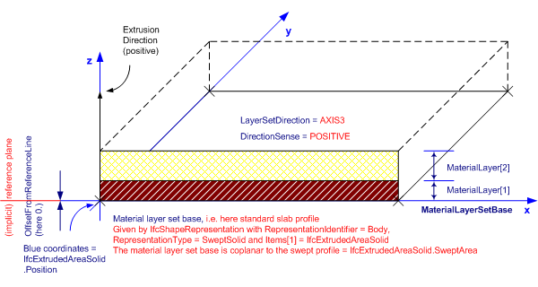
示例对于具有垂直拉伸几何表示的板,LayerSetDirection将与拉伸方向一致(正方向或负方向)。在本例中,材质层集的基础是拉伸轮廓,并与IfcExtruedReaSolid一致。位置,在DirectionSense为正的情况下,在这种情况下,单个IfcMaterialLayers从底部向正z方向构建。
注:根据IfcLabStandardCase材质使用定义,IfcLabStandard的LayerSetDirection始终为AXIS3(即沿z轴)。
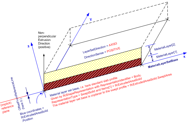
示例对于具有非垂直拉伸几何表示的板,上述准则也适用。即使拉伸方向不垂直,材料层厚度和“偏移基准线”也始终是垂直测量的。因此,材料层的总厚度不等于几何体的挤出深度。
继承结构:
Attribute inheritance
| # | Attribute | Type | Cardinality | Description | C |
|---|---|---|---|---|---|
| IfcMaterialUsageDefinition | |||||
| AssociatedTo | IfcRelAssociatesMaterial @RelatingMaterial |
S[1:?] | Use of the IfcMaterialUsageDefinition subtypes within the material association of an element occurrence. The association is established by the IfcRelAssociatesMaterial relationship. | X | |
| IfcMaterialLayerSetUsage | |||||
| 1 | ForLayerSet | IfcMaterialLayerSet | [1:1] | The IfcMaterialLayerSet set to which the usage is applied. | X |
| 2 | LayerSetDirection | IfcLayerSetDirectionEnum | [1:1] | Orientation of the material layer set relative to element reference geometry. The meaning of the value of this attribute shall be specified in the geometry use section for each element. For extruded shape representation, direction can be given along the extrusion path (e.g. for slabs) or perpendicular to it (e.g. for walls).
NOTE The LayerSetDirection for IfcWallStandardCase shall be AXIS2 (i.e. the y-axis) and for IfcSlabStandardCase and IfcPlateStandardCase it shall be AXIS3 (i.e. the z-axis). NOTE Whether the material layers of the set being used shall 'grow' into the positive or negative direction of the given axis, shall be defined by DirectionSense attribute. |
X |
| 3 | DirectionSense | IfcDirectionSenseEnum | [1:1] | Denotes whether the material layer set is oriented in positive or negative sense along the specified axis (defined by LayerSetDirection). "Positive" means that the consecutive layers (the IfcMaterialLayer instances in the list of IfcMaterialLayerSet.MaterialLayers) are placed face-by-face in the direction of the positive axis as established by LayerSetDirection: for AXIS2 it would be in +y, for AXIS3 it would be +z. "Negative" means that the layers are placed face-by-face in the direction of the negative LayerSetDirection. In both cases, starting at the material layer set base line.
NOTE the material layer set base line (MlsBase) is located by OffsetFromReferenceLine, and may be on the positive or negative side of the element reference line (or plane); positive or negative for MlsBase placement does not depend on the DirectionSense attribute, but on the relevant element axis. |
X |
| 4 | OffsetFromReferenceLine | IfcLengthMeasure | [1:1] | Offset of the material layer set base line (MlsBase) from reference geometry (line or plane) of element. The offset can be positive or negative, unless restricted for a particular building element type in its use definition or by implementer agreement. A positive value means, that the MlsBase is placed on the positive side of the reference line or plane, on the axis established by LayerSetDirection (in case of AXIS2 into the direction of +y, or in case of AXIS2 into the direction of +z). A negative value means that the MlsBase is placed on the negative side, as established by LayerSetDirection (in case of AXIS2 into the direction of -y).
NOTE the positive or negative sign in the offset only affects the MlsBase placement, it does not have any effect on the application of DirectionSense for orientation of the material layers; also DirectionSense does not change the MlsBase placement. |
X |
| 5 | ReferenceExtent | IfcPositiveLengthMeasure | [0:1] | Extent of the extrusion of the elements body shape representation to which the IfcMaterialLayerSetUsage applies. It is used as the reference value for the upper OffsetValues[2] provided by the IfcMaterialLayerSetWithOffsets subtype for included material layers.
NOTE The attribute ReferenceExtent shall be asserted, if an IfcMaterialLayerSetWithOffsets is included in the ForLayerSet.MaterialLayers list of material layers. NOTE The ReferenceExtent for IfcWallStandardCase is the reference height starting at z=0 being the XY plane of the object coordinate system. |
X |
EXPRESS Specification
ENTITY IfcMaterialLayerSetUsage
 SUBTYPE OF (IfcMaterialUsageDefinition);
  ForLayerSet : IfcMaterialLayerSet;
  LayerSetDirection : IfcLayerSetDirectionEnum;
  DirectionSense : IfcDirectionSenseEnum;
  OffsetFromReferenceLine : IfcLengthMeasure;
  ReferenceExtent : OPTIONAL IfcPositiveLengthMeasure;
END_ENTITY;
#################################

 浙公网安备 33010602011771号