

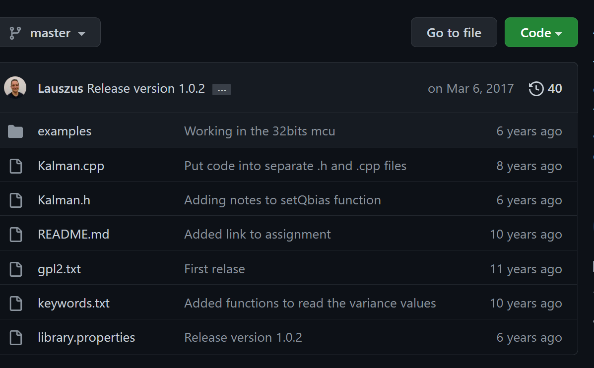
代码
https://github.com/TKJElectronics/KalmanFilter
原理剖析
原理2 卡尔曼融合滤波
https://zhuanlan.zhihu.com/p/36374943
关键点
1 他的偏置和噪声方程 根据经验给了数值
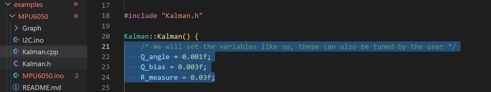
经过验证,初始参数设置为以下值时适用于大多数的IMU,并且这些初始参数将会使mpu6050工作在最佳状态;
float Q_angle = 0.001;
float Q_gyroBias = 0.003;
float R_measure = 0.03;
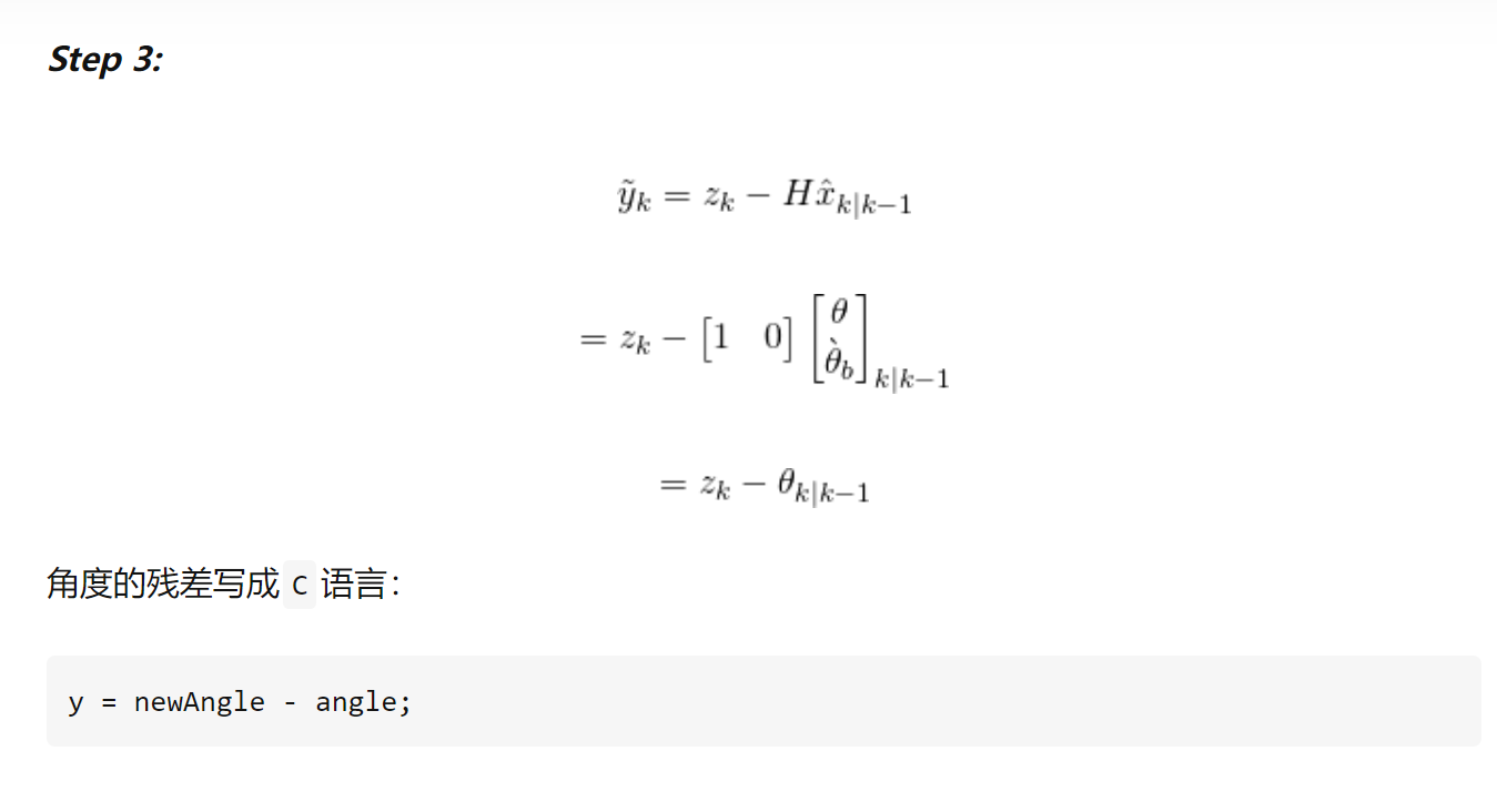
2 误差的计算 测量值-预测值
状态转移矩阵是1
测量值z 使用x和y相对于z轴重力的arctan计算的
#ifdef RESTRICT_PITCH // Eq. 25 and 26
  double roll  = atan2(accY, accZ) * RAD_TO_DEG;
  double pitch = atan(-accX / sqrt(accY * accY + accZ * accZ)) * RAD_TO_DEG;
#else // Eq. 28 and 29
  double roll  = atan(accY / sqrt(accX * accX + accZ * accZ)) * RAD_TO_DEG;
  double pitch = atan2(-accX, accZ) * RAD_TO_DEG;
#endif
进一步算残差
kalAngleX = kalmanX.getAngle(roll, gyroXrate, dt);

原理1 IMU本身运行和坐标系转换积分原理
IMU姿态解算
IMU,即惯性测量单元,一般包含三轴陀螺仪与三轴加速度计。之前的文章
https://zhuanlan.zhihu.com/p/165156300
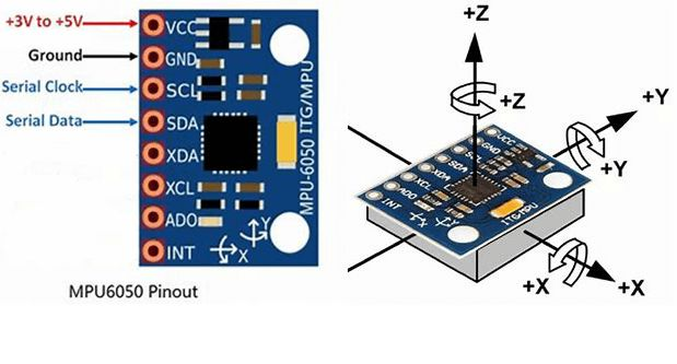
MPU6050基本功能
- 3轴陀螺仪
陀螺仪,测量的是绕xyz轴转动的角速度,对角速度积分可以得到角度。
- 3轴加速度计
加速度计,测量的是xyz方向受到的加速度。在静止时,测量到的是重力加速度,因此当物体倾斜时,根据重力的分力可以粗略的计算角度。在运动时,除了重力加速度,还叠加了由于运动产生的加速度。
工作原理

但是更大的加速度计图将有助于显示正在发生的事情。
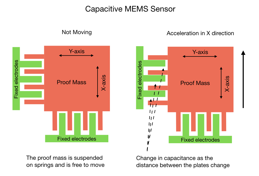
所谓的证明质量悬挂在弹簧上,并在设备加速时自由移动。固定的电极梳在自身和检测质量之间建立电容效应。当设备移动时,电容的变化会被记录并由 ADC 转换为 0 到 32,750 之间的数字值。陀螺仪以类似的方式工作,只是它基于科里奥利效应而不是加速度。
设备灵敏度
正如刚才提到的,从电容传感器读取的模拟电压被转换为 0 到 32750 值范围内的数字信号。这些值构成了陀螺仪和加速度计的测量单位。必须拆分测量单位以表示有意义的信息。MPU6050 _通过创建四个灵敏度级别来分配其测量单位,如下面的幻灯片所示。您选择的敏感级别取决于您将如何使用 IMU。例如,如果机器人要进行每秒超过 1000° (167 RPM) 的高速旋转,则应将陀螺仪灵敏度设置为 2000°。在这种情况下,由于陀螺仪必须在很短的时间内覆盖大量旋转地面,因此需要谨慎地拆分其测量单元。然而,对于大多数应用,机器人不太可能旋转得那么快,因此我们可以将灵敏度级别设置为 250°,这是默认设置。这为我们提供了每秒每度 131 个测量单位,从而提供了非常高的精度水平。
加速度计的默认设置为 2g。这应该适用于 F14 以外的大多数应用程序或构建 Tesla 的机械臂。

DMP简介
DMP就是MPU6050内部的运动引擎,全称Digital Motion Processor,直接输出四元数,可以减轻外围微处理器的工作负担且避免了繁琐的滤波和数据融合。Motion Driver是Invensense针对其运动传感器的软件包,并非全部开源,核心的算法部分是针对ARM处理器和MSP430处理器编译成了静态链接库,适用于MPU6050、MPU6500、MPU9150、MPU9250等传感器。
四元数
要理解四元数,将它们与 Yaw、Pitch、Roll 进行比较是很有用的,这是大多数人更熟悉的概念。要表示方向的变化,您首先要指定偏航角,即围绕 z 轴的旋转。然后加上Pitch,也就是绕y轴旋转。最后绕 x 轴滚动。当然,飞机可能会以不同的顺序执行此操作,或者更有可能同时执行此操作,但最终结果仍然是方向发生变化。这里的关键是你只需要三个参数 (ψ, θ, ϕ) 来表示转换。
将此与莫名其妙地需要四个参数的四元数进行对比。所以四元数首先要使用一个向量并将它指向你需要去的方向。这由下图中的红色箭头表示,并且始终是一个单位的长度。由于箭头可以指向 3D 空间中的任何地方,我们需要三个参数来定义它。方向参数以sines形式给出。一旦我们有了方向,我们就可以执行一个滚动来让我们到达最终方向。这就是第四个参数的目的。它以度数(或弧度)指定我们需要旋转多少。
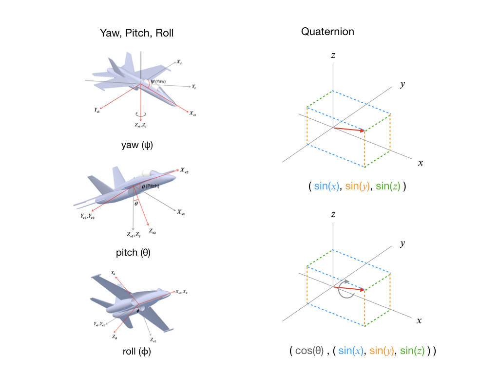
为了确保方向数据对所有应用程序都有用,DMP将其计算存储为四元数。Jeff Rowberg 的程序为您提供了一种将四元数转换为其他有用信息(例如欧拉角和线性加速度)的简单方法。
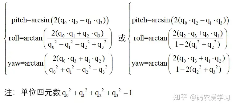
四元数转欧拉角
四元数可以方便的表示3维空间的旋转,但其概念不太好理解,可以先类比复数,复数表示的其实是2维平面中的旋转。
四元数的基本表示形式为:q0+q1*i+q2*j+q3*k,即1个实部3个虚部,具体细节本篇先不做展开介绍。
四元数虽然方便表示旋转,但其形式不太直观,旋转转换成pitch、roll、yaw的表示形式,方便观察姿态。
四元数的基本表示形式为:q0+q1*i+q2*j+q3*k,即1个实部3个虚部,具体细节本篇先不做展开介绍。
四元数虽然方便表示旋转,但其形式不太直观,旋转转换成pitch、roll、yaw的表示形式,方便观察姿态。
转换公式为:
https://zhuanlan.zhihu.com/p/195683958
本篇的姿态解算选用的旋转顺序为ZYX,即IMU坐标系初始时刻与大地坐标系重合,然后依次绕自己的Z、Y、X轴进行旋转,这里先自定义一下每次的旋转名称和符号:
- 绕IMU的Z轴旋转:航向角yaw, 转动 y 角度
- 绕IMU的Y轴旋转:俯仰角pitch,转动 p 角度
- 绕IMU的X轴旋转:横滚角row, 转动 r 角度
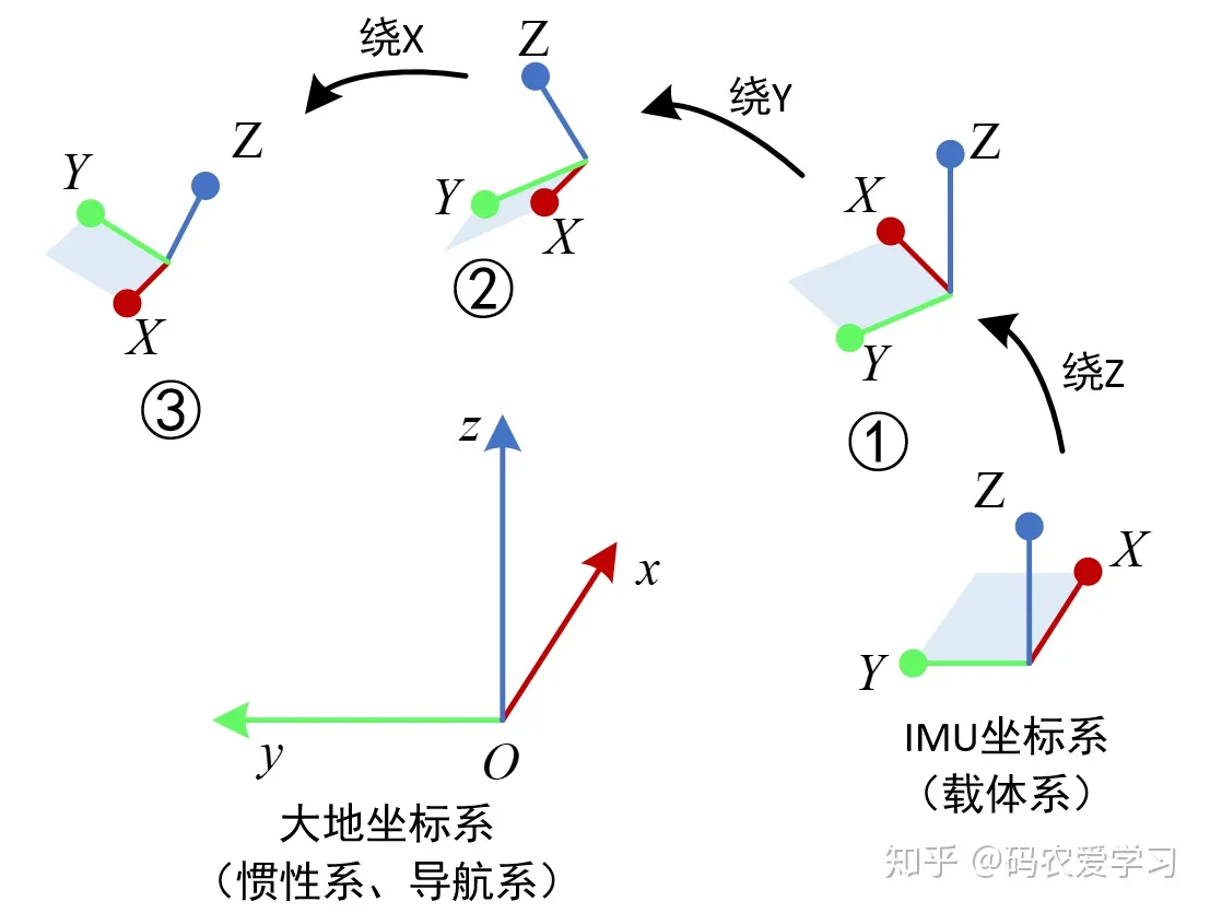
另外,横滚roll,俯仰pitch,偏航yaw的实际含义如下图:

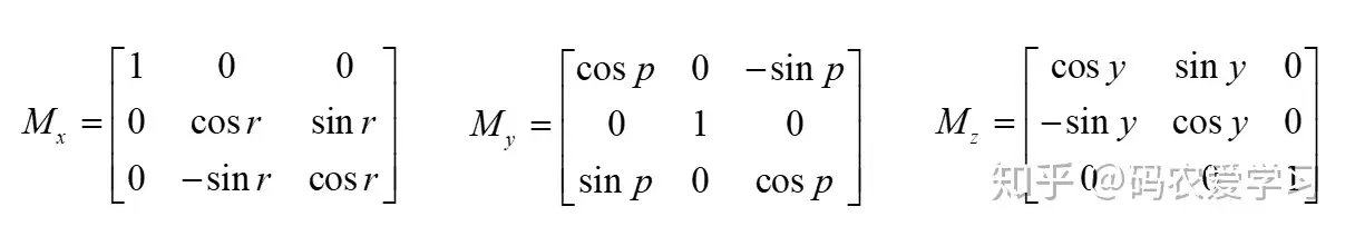
2 旋转矩阵
旋转矩阵的知识请先参阅
这里只列出本篇需要用到的3个旋转矩阵,注意这3个旋转矩阵是坐标变换的旋转矩阵。
程序表示为:
pitch = asin(-2 * q1 * q3 + 2 * q0* q2)
roll  = atan2(2 * q2 * q3 + 2 * q0 * q1, -2 * q1 * q1 - 2 * q2* q2 + 1)
yaw   = atan2(2*(q1*q2 + q0*q3),q0*q0+q1*q1-q2*q2-q3*q3)
3 欧拉角旋转
欧拉角旋转的知识请先参阅
这里需要说明的是,本篇需要用到的绕着自己运动的轴,以ZYX顺序旋转。
4 加速度计解算姿态角
加速度计测量的是其感受到的加速度,在静止的时候,其本身是没有加速运动的,但因为重力加速度的作用,根据相对运动理论,其感受的加速度与重力加速度正好相反,即读到的数据是竖直向上的。加速度计的英文简写为acc,下面用首字母a代表加速度计数据。
加速度利用静止时刻感受到重力加速度,计算姿态:
- 当加速度计水平放置,即Z轴竖直向上时,Z轴可以读到1g的数值(g为重力加速度),X轴和Y轴两个方向读到0,可以记作(0,0,g)。
- 当加速度计旋转一定的姿态时,重力加速度会在加速度的3个轴上产生相应的分量,其本质是大地坐标系下的(0,0,g)在新的加速度计自身坐标系下的坐标,加速度计读到的3个值就是(0,0,g)向量的新坐标。
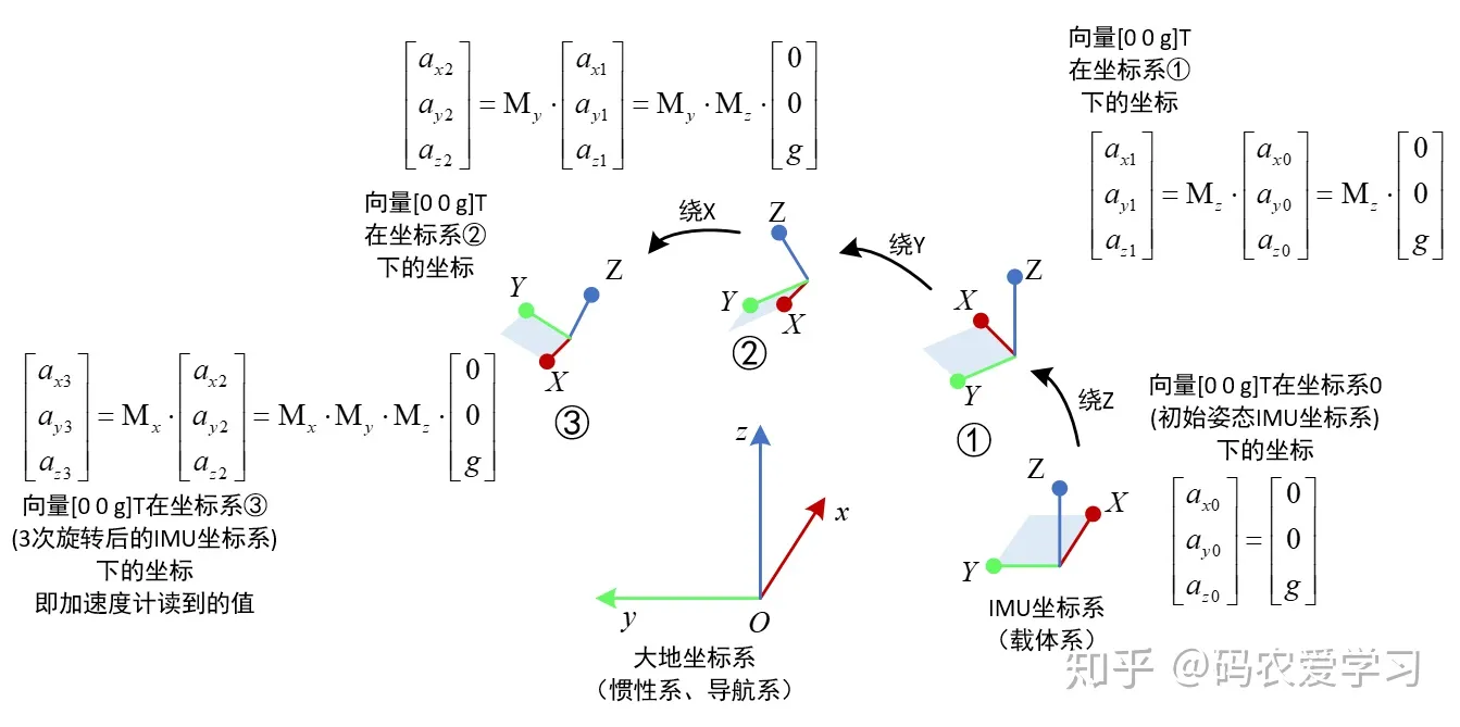
姿态的旋转选用ZYX顺序的3次旋转方式,则上述描述可表示为:
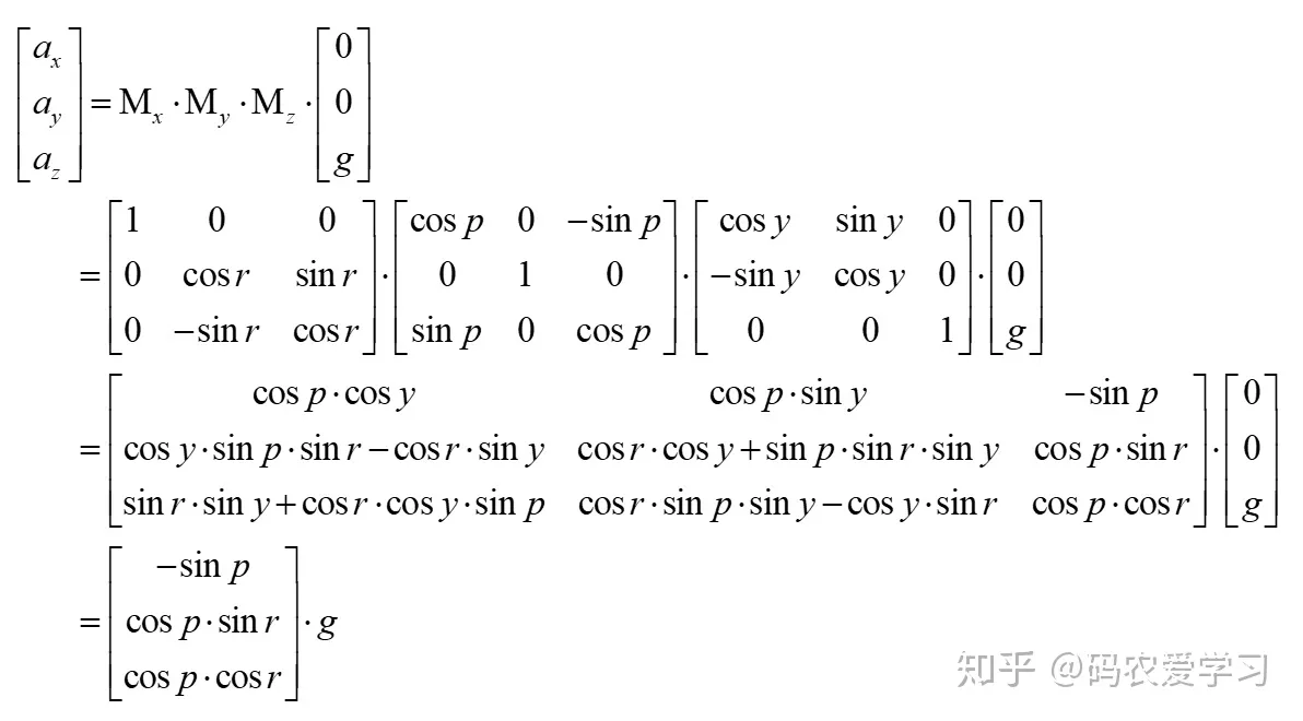
解这个方程,可以得到roll和pitch角(由于绕Z旋转时,感受到的重力加速度是不变的,因此加速度计无法计算yaw角)

3次旋转过程的分解过程如下图:
5 陀螺仪解算姿态角
陀螺仪测量的绕3个轴转动的角速度,因此,对角速度积分,可以得到角度。陀螺仪的英文简写为gyro,下面用首字母g代表陀螺仪数据。
如下图,IMU在第n个时刻的姿态角度为r、p、y,其含义为IMU坐标系从初始位置,经过绕Z旋转y角度,绕Y旋转p角度,绕X旋转r角度,得到了最终的姿态,此时需要计算下一个时刻(n+1)的姿态。设n+1时刻的姿态角为r+Δr、p+Δp、y+Δy,该姿态也是经历了3次旋转。要想计算n+1时刻的姿态,只要在n时刻姿态的基础上,加上对应的姿态角度变化量即可。姿态角度的变化量可以通过角速度与采用时间周期积分即可。

这里红框中dr/dt等角速度实际是假想的角速度,用于姿态更新,姿态更新是以大地坐标系为参考,而陀螺仪在第n个状态读出的角速度是以它自己所在的坐标系为参考,需要将读到的gyro陀螺数据经过变换,才能用于计算更新第n+1次的姿态。
那dr/dt等角速度该怎样理解呢?看下面这个图,还是将其分解为3次旋转:
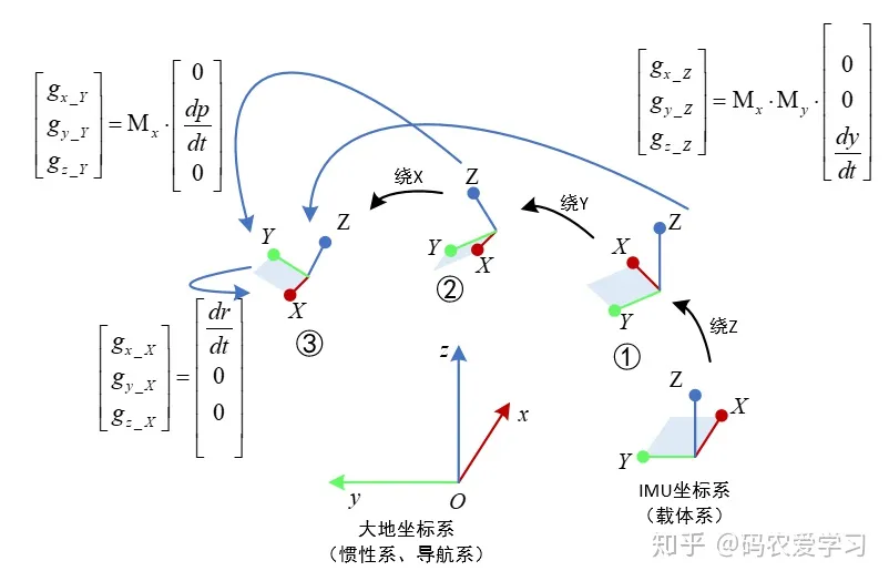
首先来看dy/dt,它是3次旋转过程中绕Z轴的yaw角的角速度,3次旋转首先就是绕着Z轴旋转,Z轴方向的单位向量可表示为[0 0 1]T,T表示向量转置,因此[0 0 dy/dt]T表示在图中状态①的坐标中绕Z的角速度。由于之后该坐标系还要经历绕Y和绕X的两次旋转,因此这里[0 0 dy/dt]T角速度在经历两次旋转后,在最终的坐标系(状态③)中的坐标也要经历两次变换。图中的[gx_Z gy_Z gz_Z]T表示3次旋转过程中绕Z轴的yaw角的角速度在最终姿态中的等效转动角速度,实际就是状态①坐标系中绕Z轴的角速度在状态③坐标系中的新的坐标。
同理,dp/dt还需要经历1次旋转变换,而dr/dt不需要经历旋转。
将dy/dt,dp/dt,dr/dt三者都变换到状态③坐标系中的新的坐标相加,实际就是状态③时刻陀螺仪自己读到的gyro数据。
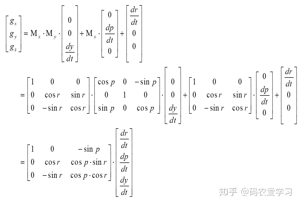
所以,从dr/dt等角速度到陀螺仪读到的角速度gx等的转换关系推导过程如下:
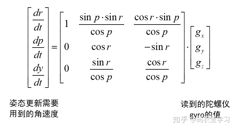
进一步,再把这里的状态③理解为状态n,则根据状态n时刻读到的陀螺仪数据,反解dy/dt等角速度数据,即可更新得到状态n+1的姿态。反解就是求逆矩阵,即:
6 姿态融合
由上面的分析可知,加速度计在静止时刻,根据感受到的重力加速度,可以计算出roll和pitch角,并且角度计算只与当前姿态有关。而陀螺仪是对时间间隔内的角速度积分,得到每一次的角度变换量,累加到上一次的姿态角上,得到新的姿态角,陀螺仪可以计算roll、pitch、yaw三个角。
实际上,加速度仅在静止时刻可以得到较准确的姿态,而陀螺仪仅对转动时的姿态变化敏感,且陀螺仪若本身存在误差,则经过连续的时间积分,误差会不断增大。因此,需要结合两者计算的姿态,进行互补融合。当然,这里只能对roll和pitch融合,因为加速度计没有得到yaw。

K为比例系数,需要根据实际来调整,如选用0.4。
代码


主代码
/* Copyright (C) 2012 Kristian Lauszus, TKJ Electronics. All rights reserved.
This software may be distributed and modified under the terms of the GNU
General Public License version 2 (GPL2) as published by the Free Software
Foundation and appearing in the file GPL2.TXT included in the packaging of
this file. Please note that GPL2 Section 2[b] requires that all works based
on this software must also be made publicly available under the terms of
the GPL2 ("Copyleft").
Contact information
-------------------
Kristian Lauszus, TKJ Electronics
Web : http://www.tkjelectronics.com
e-mail : kristianl@tkjelectronics.com
*/
#include <Wire.h>
#include "Kalman.h" // Source: https://github.com/TKJElectronics/KalmanFilter
#define RESTRICT_PITCH // Comment out to restrict roll to ±90deg instead - please read: http://www.freescale.com/files/sensors/doc/app_note/AN3461.pdf
Kalman kalmanX; // Create the Kalman instances
Kalman kalmanY;
/* IMU Data */
double accX, accY, accZ;
double gyroX, gyroY, gyroZ;
int16_t tempRaw;
double gyroXangle, gyroYangle; // Angle calculate using the gyro only
double compAngleX, compAngleY; // Calculated angle using a complementary filter
double kalAngleX, kalAngleY; // Calculated angle using a Kalman filter
uint32_t timer;
uint8_t i2cData[14]; // Buffer for I2C data
// TODO: Make calibration routine
void setup() {
Serial.begin(115200);
Wire.begin();
#if ARDUINO >= 157
Wire.setClock(400000UL); // Set I2C frequency to 400kHz
#else
TWBR = ((F_CPU / 400000UL) - 16) / 2; // Set I2C frequency to 400kHz
#endif
i2cData[0] = 7; // Set the sample rate to 1000Hz - 8kHz/(7+1) = 1000Hz
i2cData[1] = 0x00; // Disable FSYNC and set 260 Hz Acc filtering, 256 Hz Gyro filtering, 8 KHz sampling
i2cData[2] = 0x00; // Set Gyro Full Scale Range to ±250deg/s
i2cData[3] = 0x00; // Set Accelerometer Full Scale Range to ±2g
while (i2cWrite(0x19, i2cData, 4, false)); // Write to all four registers at once
while (i2cWrite(0x6B, 0x01, true)); // PLL with X axis gyroscope reference and disable sleep mode
while (i2cRead(0x75, i2cData, 1));
if (i2cData[0] != 0x68) { // Read "WHO_AM_I" register
Serial.print(F("Error reading sensor"));
while (1);
}
delay(100); // Wait for sensor to stabilize
/* Set kalman and gyro starting angle */
while (i2cRead(0x3B, i2cData, 6));
accX = (int16_t)((i2cData[0] << 8) | i2cData[1]);
accY = (int16_t)((i2cData[2] << 8) | i2cData[3]);
accZ = (int16_t)((i2cData[4] << 8) | i2cData[5]);
// Source: http://www.freescale.com/files/sensors/doc/app_note/AN3461.pdf eq. 25 and eq. 26
// atan2 outputs the value of -π to π (radians) - see http://en.wikipedia.org/wiki/Atan2
// It is then converted from radians to degrees
#ifdef RESTRICT_PITCH // Eq. 25 and 26
double roll = atan2(accY, accZ) * RAD_TO_DEG;
double pitch = atan(-accX / sqrt(accY * accY + accZ * accZ)) * RAD_TO_DEG;
#else // Eq. 28 and 29
double roll = atan(accY / sqrt(accX * accX + accZ * accZ)) * RAD_TO_DEG;
double pitch = atan2(-accX, accZ) * RAD_TO_DEG;
#endif
kalmanX.setAngle(roll); // Set starting angle
kalmanY.setAngle(pitch);
gyroXangle = roll;
gyroYangle = pitch;
compAngleX = roll;
compAngleY = pitch;
timer = micros();
}
void loop() {
/* Update all the values */
while (i2cRead(0x3B, i2cData, 14));
accX = (int16_t)((i2cData[0] << 8) | i2cData[1]);
accY = (int16_t)((i2cData[2] << 8) | i2cData[3]);
accZ = (int16_t)((i2cData[4] << 8) | i2cData[5]);
tempRaw = (int16_t)((i2cData[6] << 8) | i2cData[7]);
gyroX = (int16_t)((i2cData[8] << 8) | i2cData[9]);
gyroY = (int16_t)((i2cData[10] << 8) | i2cData[11]);
gyroZ = (int16_t)((i2cData[12] << 8) | i2cData[13]);;
double dt = (double)(micros() - timer) / 1000000; // Calculate delta time
timer = micros();
// Source: http://www.freescale.com/files/sensors/doc/app_note/AN3461.pdf eq. 25 and eq. 26
// atan2 outputs the value of -π to π (radians) - see http://en.wikipedia.org/wiki/Atan2
// It is then converted from radians to degrees
#ifdef RESTRICT_PITCH // Eq. 25 and 26
double roll = atan2(accY, accZ) * RAD_TO_DEG;
double pitch = atan(-accX / sqrt(accY * accY + accZ * accZ)) * RAD_TO_DEG;
#else // Eq. 28 and 29
double roll = atan(accY / sqrt(accX * accX + accZ * accZ)) * RAD_TO_DEG;
double pitch = atan2(-accX, accZ) * RAD_TO_DEG;
#endif
double gyroXrate = gyroX / 131.0; // Convert to deg/s
double gyroYrate = gyroY / 131.0; // Convert to deg/s
#ifdef RESTRICT_PITCH
// This fixes the transition problem when the accelerometer angle jumps between -180 and 180 degrees
if ((roll < -90 && kalAngleX > 90) || (roll > 90 && kalAngleX < -90)) {
kalmanX.setAngle(roll);
compAngleX = roll;
kalAngleX = roll;
gyroXangle = roll;
} else
kalAngleX = kalmanX.getAngle(roll, gyroXrate, dt); // Calculate the angle using a Kalman filter
if (abs(kalAngleX) > 90)
gyroYrate = -gyroYrate; // Invert rate, so it fits the restriced accelerometer reading
kalAngleY = kalmanY.getAngle(pitch, gyroYrate, dt);
#else
// This fixes the transition problem when the accelerometer angle jumps between -180 and 180 degrees
if ((pitch < -90 && kalAngleY > 90) || (pitch > 90 && kalAngleY < -90)) {
kalmanY.setAngle(pitch);
compAngleY = pitch;
kalAngleY = pitch;
gyroYangle = pitch;
} else
kalAngleY = kalmanY.getAngle(pitch, gyroYrate, dt); // Calculate the angle using a Kalman filter
if (abs(kalAngleY) > 90)
gyroXrate = -gyroXrate; // Invert rate, so it fits the restriced accelerometer reading
kalAngleX = kalmanX.getAngle(roll, gyroXrate, dt); // Calculate the angle using a Kalman filter
#endif
gyroXangle += gyroXrate * dt; // Calculate gyro angle without any filter
gyroYangle += gyroYrate * dt;
//gyroXangle += kalmanX.getRate() * dt; // Calculate gyro angle using the unbiased rate
//gyroYangle += kalmanY.getRate() * dt;
compAngleX = 0.93 * (compAngleX + gyroXrate * dt) + 0.07 * roll; // Calculate the angle using a Complimentary filter
compAngleY = 0.93 * (compAngleY + gyroYrate * dt) + 0.07 * pitch;
// Reset the gyro angle when it has drifted too much
if (gyroXangle < -180 || gyroXangle > 180)
gyroXangle = kalAngleX;
if (gyroYangle < -180 || gyroYangle > 180)
gyroYangle = kalAngleY;
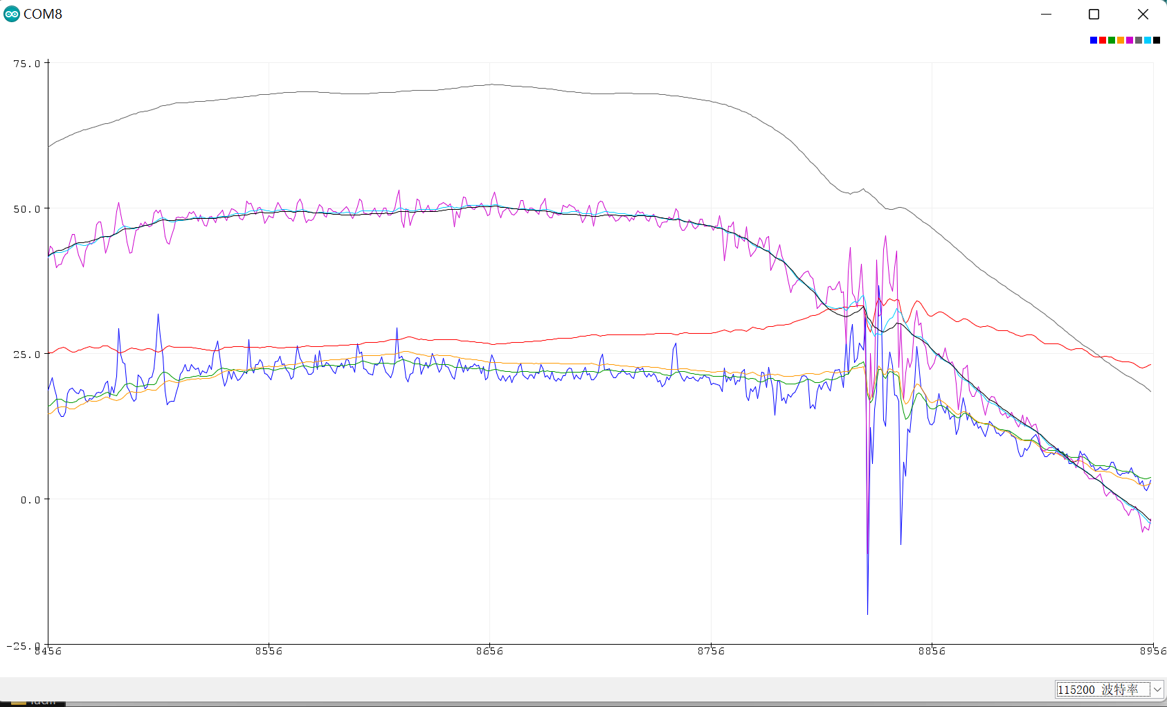
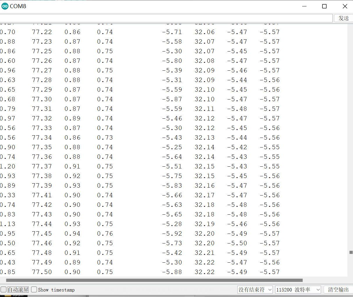
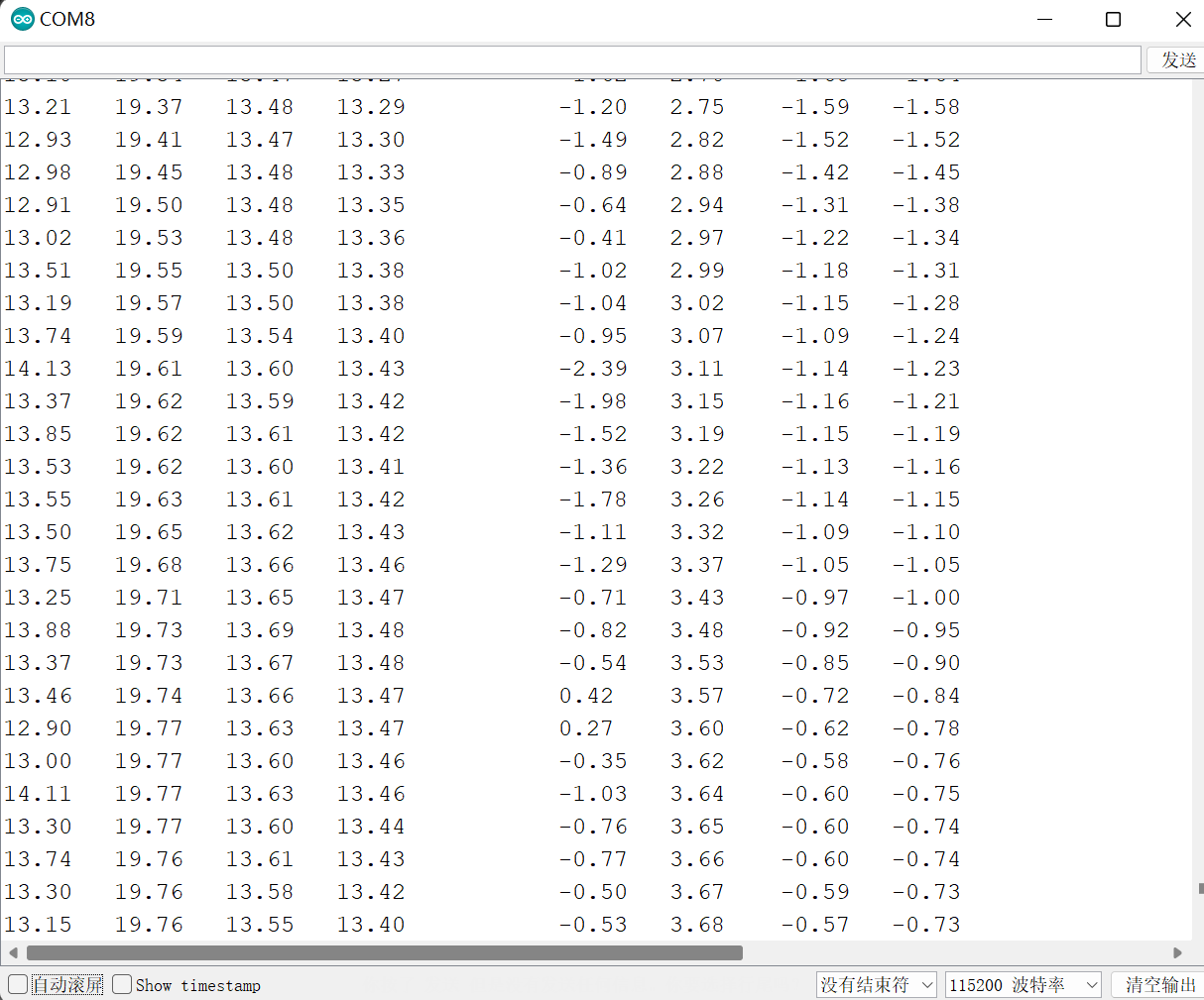
/* Print Data */
#if 0 // Set to 1 to activate
Serial.print(accX); Serial.print("\t");
Serial.print(accY); Serial.print("\t");
Serial.print(accZ); Serial.print("\t");
Serial.print(gyroX); Serial.print("\t");
Serial.print(gyroY); Serial.print("\t");
Serial.print(gyroZ); Serial.print("\t");
Serial.print("\t");
#endif
Serial.print(roll); Serial.print("\t");
Serial.print(gyroXangle); Serial.print("\t");
Serial.print(compAngleX); Serial.print("\t");
Serial.print(kalAngleX); Serial.print("\t");
Serial.print("\t");
Serial.print(pitch); Serial.print("\t");
Serial.print(gyroYangle); Serial.print("\t");
Serial.print(compAngleY); Serial.print("\t");
Serial.print(kalAngleY); Serial.print("\t");
#if 0 // Set to 1 to print the temperature
Serial.print("\t");
double temperature = (double)tempRaw / 340.0 + 36.53;
Serial.print(temperature); Serial.print("\t");
#endif
Serial.print("\r\n");
delay(2);
}
I2C.ino
/* Copyright (C) 2012 Kristian Lauszus, TKJ Electronics. All rights reserved.

 This software may be distributed and modified under the terms of the GNU
 General Public License version 2 (GPL2) as published by the Free Software
 Foundation and appearing in the file GPL2.TXT included in the packaging of
 this file. Please note that GPL2 Section 2[b] requires that all works based
 on this software must also be made publicly available under the terms of
 the GPL2 ("Copyleft").

 Contact information
 -------------------

 Kristian Lauszus, TKJ Electronics
 Web      :  http://www.tkjelectronics.com
 e-mail   :  kristianl@tkjelectronics.com
 */

const uint8_t IMUAddress = 0x68; // AD0 is logic low on the PCB
const uint16_t I2C_TIMEOUT = 1000; // Used to check for errors in I2C communication

uint8_t i2cWrite(uint8_t registerAddress, uint8_t data, bool sendStop) {
  return i2cWrite(registerAddress, &data, 1, sendStop); // Returns 0 on success
}

uint8_t i2cWrite(uint8_t registerAddress, uint8_t *data, uint8_t length, bool sendStop) {
  Wire.beginTransmission(IMUAddress);
  Wire.write(registerAddress);
  Wire.write(data, length);
  uint8_t rcode = Wire.endTransmission(sendStop); // Returns 0 on success
  if (rcode) {
    Serial.print(F("i2cWrite failed: "));
    Serial.println(rcode);
  }
  return rcode; // See: http://arduino.cc/en/Reference/WireEndTransmission
}

uint8_t i2cRead(uint8_t registerAddress, uint8_t *data, uint8_t nbytes) {
  uint32_t timeOutTimer;
  Wire.beginTransmission(IMUAddress);
  Wire.write(registerAddress);
  uint8_t rcode = Wire.endTransmission(false); // Don't release the bus
  if (rcode) {
    Serial.print(F("i2cRead failed: "));
    Serial.println(rcode);
    return rcode; // See: http://arduino.cc/en/Reference/WireEndTransmission
  }
  Wire.requestFrom(IMUAddress, nbytes, (uint8_t)true); // Send a repeated start and then release the bus after reading
  for (uint8_t i = 0; i < nbytes; i++) {
    if (Wire.available())
      data[i] = Wire.read();
    else {
      timeOutTimer = micros();
      while (((micros() - timeOutTimer) < I2C_TIMEOUT) && !Wire.available());
      if (Wire.available())
        data[i] = Wire.read();
      else {
        Serial.println(F("i2cRead timeout"));
        return 5; // This error value is not already taken by endTransmission
      }
    }
  }
  return 0; // Success
}
Kalman.h
/* Copyright (C) 2012 Kristian Lauszus, TKJ Electronics. All rights reserved.

 This software may be distributed and modified under the terms of the GNU
 General Public License version 2 (GPL2) as published by the Free Software
 Foundation and appearing in the file GPL2.TXT included in the packaging of
 this file. Please note that GPL2 Section 2[b] requires that all works based
 on this software must also be made publicly available under the terms of
 the GPL2 ("Copyleft").

 Contact information
 -------------------

 Kristian Lauszus, TKJ Electronics
 Web      :  http://www.tkjelectronics.com
 e-mail   :  kristianl@tkjelectronics.com
 */

#ifndef _Kalman_h_
#define _Kalman_h_

class Kalman {
public:
    Kalman();

    // The angle should be in degrees and the rate should be in degrees per second and the delta time in seconds
    float getAngle(float newAngle, float newRate, float dt);

    void setAngle(float angle); // Used to set angle, this should be set as the starting angle
    float getRate(); // Return the unbiased rate

    /* These are used to tune the Kalman filter */
    void setQangle(float Q_angle);
    /**
     * setQbias(float Q_bias)
     * Default value (0.003f) is in Kalman.cpp.
     * Raise this to follow input more closely,
     * lower this to smooth result of kalman filter.
     */
    void setQbias(float Q_bias);
    void setRmeasure(float R_measure);

    float getQangle();
    float getQbias();
    float getRmeasure();

private:
    /* Kalman filter variables */
    float Q_angle; // Process noise variance for the accelerometer
    float Q_bias; // Process noise variance for the gyro bias
    float R_measure; // Measurement noise variance - this is actually the variance of the measurement noise

    float angle; // The angle calculated by the Kalman filter - part of the 2x1 state vector
    float bias; // The gyro bias calculated by the Kalman filter - part of the 2x1 state vector
    float rate; // Unbiased rate calculated from the rate and the calculated bias - you have to call getAngle to update the rate

    float P[2][2]; // Error covariance matrix - This is a 2x2 matrix
};

#endif
Kalman.cpp
/* Copyright (C) 2012 Kristian Lauszus, TKJ Electronics. All rights reserved.

 This software may be distributed and modified under the terms of the GNU
 General Public License version 2 (GPL2) as published by the Free Software
 Foundation and appearing in the file GPL2.TXT included in the packaging of
 this file. Please note that GPL2 Section 2[b] requires that all works based
 on this software must also be made publicly available under the terms of
 the GPL2 ("Copyleft").

 Contact information
 -------------------

 Kristian Lauszus, TKJ Electronics
 Web      :  http://www.tkjelectronics.com
 e-mail   :  kristianl@tkjelectronics.com
 */

#include "Kalman.h"

Kalman::Kalman() {
    /* We will set the variables like so, these can also be tuned by the user */
    Q_angle = 0.001f;
    Q_bias = 0.003f;
    R_measure = 0.03f;

    angle = 0.0f; // Reset the angle
    bias = 0.0f; // Reset bias

    P[0][0] = 0.0f; // Since we assume that the bias is 0 and we know the starting angle (use setAngle), the error covariance matrix is set like so - see: http://en.wikipedia.org/wiki/Kalman_filter#Example_application.2C_technical
    P[0][1] = 0.0f;
    P[1][0] = 0.0f;
    P[1][1] = 0.0f;
};

// The angle should be in degrees and the rate should be in degrees per second and the delta time in seconds
float Kalman::getAngle(float newAngle, float newRate, float dt) {
    // KasBot V2  -  Kalman filter module - http://www.x-firm.com/?page_id=145
    // Modified by Kristian Lauszus
    // See my blog post for more information: http://blog.tkjelectronics.dk/2012/09/a-practical-approach-to-kalman-filter-and-how-to-implement-it

    // Discrete Kalman filter time update equations - Time Update ("Predict")
    // Update xhat - Project the state ahead
    /* Step 1 */
    rate = newRate - bias;
    angle += dt * rate;

    // Update estimation error covariance - Project the error covariance ahead
    /* Step 2 */
    P[0][0] += dt * (dt*P[1][1] - P[0][1] - P[1][0] + Q_angle);
    P[0][1] -= dt * P[1][1];
    P[1][0] -= dt * P[1][1];
    P[1][1] += Q_bias * dt;

    // Discrete Kalman filter measurement update equations - Measurement Update ("Correct")
    // Calculate Kalman gain - Compute the Kalman gain
    /* Step 4 */
    float S = P[0][0] + R_measure; // Estimate error
    /* Step 5 */
    float K[2]; // Kalman gain - This is a 2x1 vector
    K[0] = P[0][0] / S;
    K[1] = P[1][0] / S;

    // Calculate angle and bias - Update estimate with measurement zk (newAngle)
    /* Step 3 */
    float y = newAngle - angle; // Angle difference
    /* Step 6 */
    angle += K[0] * y;
    bias += K[1] * y;

    // Calculate estimation error covariance - Update the error covariance
    /* Step 7 */
    float P00_temp = P[0][0];
    float P01_temp = P[0][1];

    P[0][0] -= K[0] * P00_temp;
    P[0][1] -= K[0] * P01_temp;
    P[1][0] -= K[1] * P00_temp;
    P[1][1] -= K[1] * P01_temp;

    return angle;
};

void Kalman::setAngle(float angle) { this->angle = angle; }; // Used to set angle, this should be set as the starting angle
float Kalman::getRate() { return this->rate; }; // Return the unbiased rate

/* These are used to tune the Kalman filter */
void Kalman::setQangle(float Q_angle) { this->Q_angle = Q_angle; };
void Kalman::setQbias(float Q_bias) { this->Q_bias = Q_bias; };
void Kalman::setRmeasure(float R_measure) { this->R_measure = R_measure; };

float Kalman::getQangle() { return this->Q_angle; };
float Kalman::getQbias() { return this->Q_bias; };
float Kalman::getRmeasure() { return this->R_measure; };
例子2 类基础3轴角度
z轴实测不稳定
#include <Wire.h>


uint32_t timer;
uint8_t i2cData[14]; // Buffer for I2C data

unsigned long now, lastTime = 0;
float dt;                                   //微分时间

int16_t ax, ay, az, gx, gy, gz;             //加速度计陀螺仪原始数据
float aax=0, aay=0,aaz=0, agx=0, agy=0, agz=0;    //角度变量
long axo = 0, ayo = 0, azo = 0;             //加速度计偏移量
long gxo = 0, gyo = 0, gzo = 0;             //陀螺仪偏移量

float pi = 3.1415926;
float AcceRatio = 16384.0;                  //加速度计比例系数
float GyroRatio = 131.0;                    //陀螺仪比例系数

uint8_t n_sample = 8;                       //加速度计滤波算法采样个数
float aaxs[8] = {0}, aays[8] = {0}, aazs[8] = {0};         //x,y轴采样队列
long aax_sum, aay_sum,aaz_sum;                      //x,y轴采样和

float a_x[10]={0}, a_y[10]={0},a_z[10]={0} ,g_x[10]={0} ,g_y[10]={0},g_z[10]={0}; //加速度计协方差计算队列
float Px=1, Rx, Kx, Sx, Vx, Qx;             //x轴卡尔曼变量
float Py=1, Ry, Ky, Sy, Vy, Qy;             //y轴卡尔曼变量
float Pz=1, Rz, Kz, Sz, Vz, Qz;             //z轴卡尔曼变量


void setup()
{

    Serial.begin(115200);

    Wire.begin();
    #if ARDUINO >= 157
      Wire.setClock(400000UL); // Set I2C frequency to 400kHz
    #else
      TWBR = ((F_CPU / 400000UL) - 16) / 2; // Set I2C frequency to 400kHz
    #endif

    i2cData[0] = 7; // Set the sample rate to 1000Hz - 8kHz/(7+1) = 1000Hz
    i2cData[1] = 0x00; // Disable FSYNC and set 260 Hz Acc filtering, 256 Hz Gyro filtering, 8 KHz sampling
    i2cData[2] = 0x00; // Set Gyro Full Scale Range to ±250deg/s
    i2cData[3] = 0x00; // Set Accelerometer Full Scale Range to ±2g
    while (i2cWrite(0x19, i2cData, 4, false)); // Write to all four registers at once
    while (i2cWrite(0x6B, 0x01, true)); // PLL with X axis gyroscope reference and disable sleep mode

    while (i2cRead(0x75, i2cData, 1));
    if (i2cData[0] != 0x68) { // Read "WHO_AM_I" register
      Serial.print(F("Error reading sensor"));
      while (1);
    }

    delay(100); // Wait for sensor to stabilize
    /* Set kalman and gyro starting angle */


    unsigned short times = 200;             //采样次数
    for(int i=0;i<times;i++)
    {
        //accelgyro.getMotion6(&ax, &ay, &az, &gx, &gy, &gz); //读取六轴原始数值

        while (i2cRead(0x3B, i2cData, 14));
        ax = (int16_t)((i2cData[0] << 8) | i2cData[1]);
        ay = (int16_t)((i2cData[2] << 8) | i2cData[3]);
        az = (int16_t)((i2cData[4] << 8) | i2cData[5]);

        gx = (int16_t)((i2cData[8] << 8) | i2cData[9]);
        gy = (int16_t)((i2cData[10] << 8) | i2cData[11]);
        gz = (int16_t)((i2cData[12] << 8) | i2cData[13]);;

        axo += ax; ayo += ay; azo += az;      //采样和
        gxo += gx; gyo += gy; gzo += gz;

    }

    axo /= times; ayo /= times; azo /= times; //计算加速度计偏移
    gxo /= times; gyo /= times; gzo /= times; //计算陀螺仪偏移
}

void loop()
{
    unsigned long now = millis();             //当前时间(ms)
    dt = (now - lastTime) / 1000.0;           //微分时间(s)
    lastTime = now;                           //上一次采样时间(ms)


    while (i2cRead(0x3B, i2cData, 14));
    ax = (int16_t)((i2cData[0] << 8) | i2cData[1]);
    ay = (int16_t)((i2cData[2] << 8) | i2cData[3]);
    az = (int16_t)((i2cData[4] << 8) | i2cData[5]);

    gx = (int16_t)((i2cData[8] << 8) | i2cData[9]);
    gy = (int16_t)((i2cData[10] << 8) | i2cData[11]);
    gz = (int16_t)((i2cData[12] << 8) | i2cData[13]);;

    float accx = ax / AcceRatio;              //x轴加速度
    float accy = ay / AcceRatio;              //y轴加速度
    float accz = az / AcceRatio;              //z轴加速度

    aax = atan(accy / accz) * (-180) / pi;    //y轴对于z轴的夹角
    aay = atan(accx / accz) * 180 / pi;       //x轴对于z轴的夹角
    aaz = atan(accz / accy) * 180 / pi;       //z轴对于y轴的夹角

    aax_sum = 0;                              // 对于加速度计原始数据的滑动加权滤波算法
    aay_sum = 0;
    aaz_sum = 0;

    for(int i=1;i<n_sample;i++)
    {
        aaxs[i-1] = aaxs[i];
        aax_sum += aaxs[i] * i;
        aays[i-1] = aays[i];
        aay_sum += aays[i] * i;
        aazs[i-1] = aazs[i];
        aaz_sum += aazs[i] * i;

    }

    aaxs[n_sample-1] = aax;
    aax_sum += aax * n_sample;
    aax = (aax_sum / (11*n_sample/2.0)) * 9 / 7.0; //角度调幅至0-90°
    aays[n_sample-1] = aay;                        //此处应用实验法取得合适的系数
    aay_sum += aay * n_sample;                     //本例系数为9/7
    aay = (aay_sum / (11*n_sample/2.0)) * 9 / 7.0;
    aazs[n_sample-1] = aaz;
    aaz_sum += aaz * n_sample;
    aaz = (aaz_sum / (11*n_sample/2.0)) * 9 / 7.0;

    float gyrox = - (gx-gxo) / GyroRatio * dt; //x轴角速度
    float gyroy = - (gy-gyo) / GyroRatio * dt; //y轴角速度
    float gyroz = - (gz-gzo) / GyroRatio * dt; //z轴角速度
    agx += gyrox;                             //x轴角速度积分
    agy += gyroy;                             //x轴角速度积分
    agz += gyroz;

    /* kalman start */
    Sx = 0; Rx = 0;
    Sy = 0; Ry = 0;
    Sz = 0; Rz = 0;

    for(int i=1;i<10;i++)
    {                 //测量值平均值运算
        a_x[i-1] = a_x[i];                      //即加速度平均值
        Sx += a_x[i];
        a_y[i-1] = a_y[i];
        Sy += a_y[i];
        a_z[i-1] = a_z[i];
        Sz += a_z[i];

    }

    a_x[9] = aax;
    Sx += aax;
    Sx /= 10;                                 //x轴加速度平均值
    a_y[9] = aay;
    Sy += aay;
    Sy /= 10;                                 //y轴加速度平均值
    a_z[9] = aaz;
    Sz += aaz;
    Sz /= 10;

    for(int i=0;i<10;i++)
    {
        Rx += sq(a_x[i] - Sx);
        Ry += sq(a_y[i] - Sy);
        Rz += sq(a_z[i] - Sz);

    }

    Rx = Rx / 9;                              //得到方差
    Ry = Ry / 9;
    Rz = Rz / 9;

    Px = Px + 0.0025;                         // 0.0025在下面有说明...
    Kx = Px / (Px + Rx);                      //计算卡尔曼增益
    agx = agx + Kx * (aax - agx);             //陀螺仪角度与加速度计速度叠加
    Px = (1 - Kx) * Px;                       //更新p值

    Py = Py + 0.0025;
    Ky = Py / (Py + Ry);
    agy = agy + Ky * (aay - agy);
    Py = (1 - Ky) * Py;

    Pz = Pz + 0.0025;
    Kz = Pz / (Pz + Rz);
    agz = agz + Kz * (aaz - agz);
    Pz = (1 - Kz) * Pz;

    /* kalman end */

    Serial.print(agx);Serial.print(",");
    Serial.print(agy);Serial.print(",");
    Serial.print(agz);Serial.println();

}

 浙公网安备 33010602011771号