

一种在block design中,使用dma+fifo+触发模块的采集模式记录
这个方式其实比较麻烦,但是确实是可用的,简单来讲,就是用普通FIFO代替了stream fifo 来实现稳定,大容量的dma传输(代码在最后面),这边做下记录(实际最好还是用stream fifo),不过还是建议使用我另一篇随笔里的方法。https://www.cnblogs.com/daydaygood/p/18811676
Get_trigger_and_data模块是用来给fifo产生数据、写时钟和写使能,在fifo full信号满的时候停止写使能,在外部start_flag信号为高的时候开始写使能。
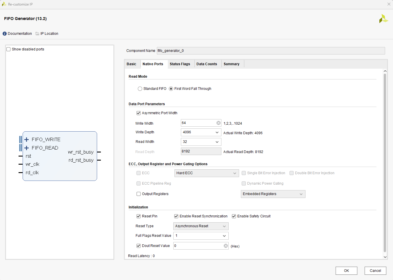
jesd_data_parse模块是自定义axi模块,用来给fifo产生读时钟和读使能,读时钟是固定的,读使能来自后级dma驱动的ready和jesd_daa_parse模块里vallid信号的耦合,这里其实做了一步数据位宽转换,64-32。

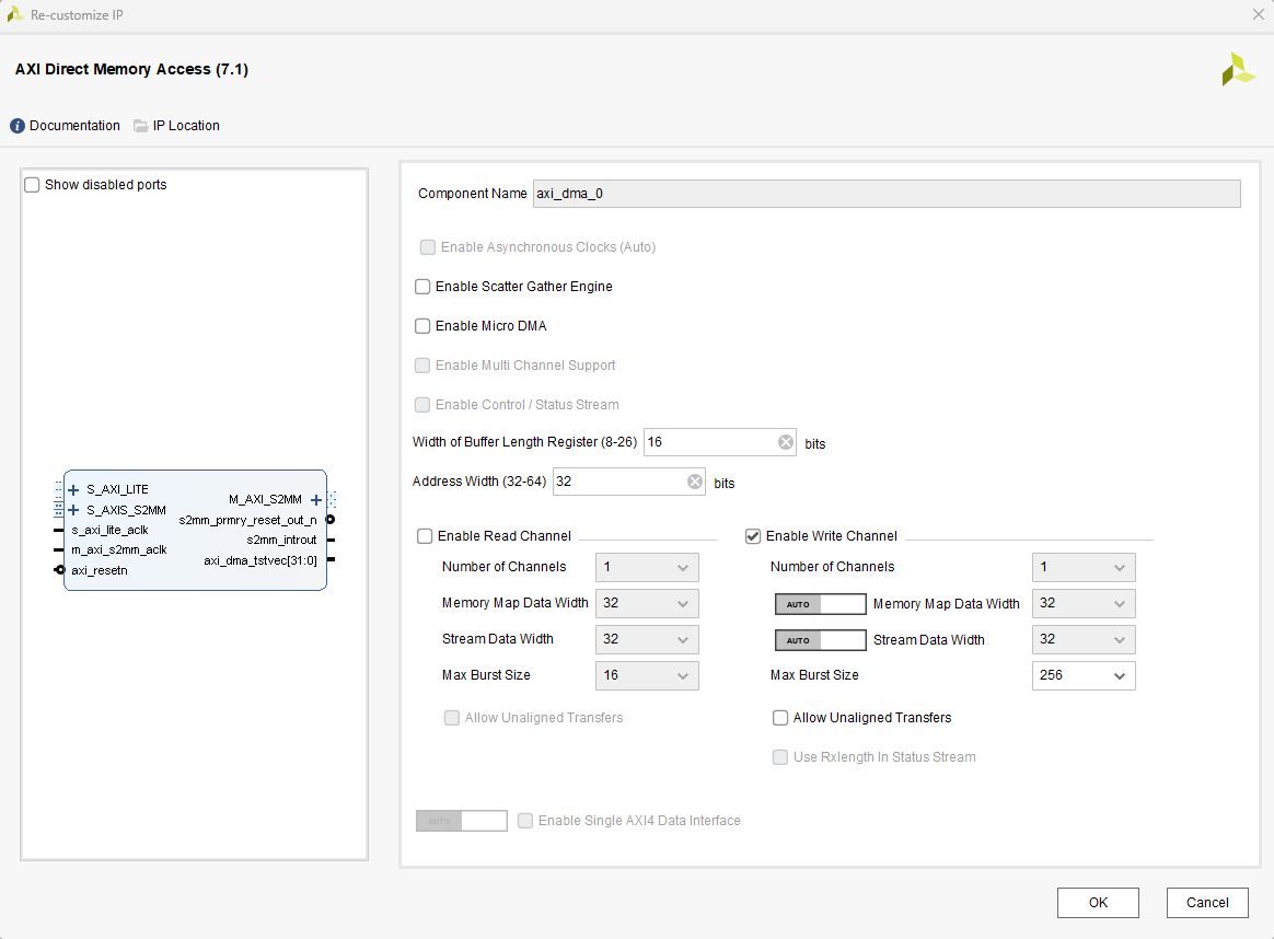
jesd_data_parse模块与后级的dma模块相连接。

所有关联的模块的复位信号来自于dma的复位信号输出。写时钟250MHz,数据64位宽,读时钟100MHz,数据32位宽。

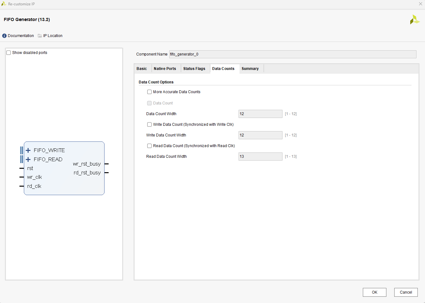
下面是IP核具体设置,实际可根据经验和需求自行打磨。


下面是rtl和自定义IP核代码,实际可根据经验和需求自行打磨。
点击查看代码
`timescale 1ns / 1ps

module Get_trigger_and_data_generate(
    input   wire            M_AXIS_ACLK,
    input   wire            M_AXIS_ARESETN,

    input   wire            glblclk,
    input 	wire	[63:0]	rx_data,
    input 	wire			start_flag,
    input   wire            full,

    output  wire    [63:0]  adc_data_64,
    output  reg             wr_en,
    output  wire            wr_clk
    );

wire	[15:0]	adc_sample_1;
wire	[15:0]	adc_sample_2;
wire	[15:0]	adc_sample_3;
wire	[15:0]	adc_sample_4;

assign	adc_sample_1	=	{{2{rx_data[31]}}, rx_data[31:24], rx_data[63:58]};
assign	adc_sample_2	=	{{2{rx_data[23]}}, rx_data[23:16], rx_data[55:50]};
assign	adc_sample_3	=	{{2{rx_data[15]}}, rx_data[15: 8], rx_data[47:42]};
assign	adc_sample_4	=	{{2{rx_data[ 7]}}, rx_data[7 : 0], rx_data[39:34]};

assign adc_data_64 = {adc_sample_4,adc_sample_3,adc_sample_2,adc_sample_1};

	// for fifo wr_en
always @(posedge M_AXIS_ACLK) begin
    if (!M_AXIS_ARESETN) begin
        wr_en	<=	1'd0;
    end	else	if (full) begin
        wr_en	<=	1'd0;
    end	else	if (start_flag) begin
        wr_en	<=	1'd1;
    end
end

assign wr_clk = glblclk;

endmodule
点击查看代码
`timescale 1 ns / 1 ps

	module jesd_data_parse_v1_0_M00_AXIS #
	(
		// Users to add parameters here

		// User parameters ends
		// Do not modify the parameters beyond this line

		// Width of S_AXIS address bus. The slave accepts the read and write addresses of width C_M_AXIS_TDATA_WIDTH.
		parameter integer C_M_AXIS_TDATA_WIDTH	= 32,
		// Start count is the number of clock cycles the master will wait before initiating/issuing any transaction.
		parameter integer C_M_START_COUNT	= 32
	)
	(
		// Users to add ports here
		output 	wire			rd_clk,
		output 	wire 			rd_en,
		input	wire	[31:0]	data,

		// User ports ends
		// Do not modify the ports beyond this line

		// Global ports
		input wire  M_AXIS_ACLK,
		//
		input wire  M_AXIS_ARESETN,
		// Master Stream Ports. TVALID indicates that the master is driving a valid transfer, A transfer takes place when both TVALID and TREADY are asserted.
		output wire  M_AXIS_TVALID,
		// TDATA is the primary payload that is used to provide the data that is passing across the interface from the master.
		output wire [C_M_AXIS_TDATA_WIDTH-1 : 0] M_AXIS_TDATA,
		// TSTRB is the byte qualifier that indicates whether the content of the associated byte of TDATA is processed as a data byte or a position byte.
		output wire [(C_M_AXIS_TDATA_WIDTH/8)-1 : 0] M_AXIS_TSTRB,
		// TLAST indicates the boundary of a packet.
		output wire  M_AXIS_TLAST,
		// TREADY indicates that the slave can accept a transfer in the current cycle.
		input wire  M_AXIS_TREADY
	);
	// Total number of output data
	localparam NUMBER_OF_OUTPUT_WORDS = 8192;

	// function called clogb2 that returns an integer which has the
	// value of the ceiling of the log base 2.
	function integer clogb2 (input integer bit_depth);
	  begin
	    for(clogb2=0; bit_depth>0; clogb2=clogb2+1)
	      bit_depth = bit_depth >> 1;
	  end
	endfunction

	// WAIT_COUNT_BITS is the width of the wait counter.
	localparam integer WAIT_COUNT_BITS = clogb2(C_M_START_COUNT-1);

	// bit_num gives the minimum number of bits needed to address 'depth' size of FIFO.
	localparam bit_num  = clogb2(NUMBER_OF_OUTPUT_WORDS);

	// Define the states of state machine
	// The control state machine oversees the writing of input streaming data to the FIFO,
	// and outputs the streaming data from the FIFO
	localparam [1:0] IDLE = 2'b00,        // This is the initial/idle state

	                INIT_COUNTER  = 2'b01, // This state initializes the counter, once
	                                // the counter reaches C_M_START_COUNT count,
	                                // the state machine changes state to SEND_STREAM
	                SEND_STREAM   = 2'b10; // In this state the
	                                     // stream data is output through M_AXIS_TDATA
	// State variable
	reg [1:0] mst_exec_state;
	// Example design FIFO read pointer
	reg [bit_num-1:0] read_pointer;

	// AXI Stream internal signals
	//wait counter. The master waits for the user defined number of clock cycles before initiating a transfer.
	reg [WAIT_COUNT_BITS-1 : 0] 	count;
	//streaming data valid
	wire  	axis_tvalid;
	//streaming data valid delayed by one clock cycle
	reg  	axis_tvalid_delay;
	//Last of the streaming data
	wire  	axis_tlast;
	//Last of the streaming data delayed by one clock cycle
	reg  	axis_tlast_delay;
	//FIFO implementation signals
	wire 	[C_M_AXIS_TDATA_WIDTH-1 : 0] 	stream_data_out;
	wire  	tx_en;
	//The master has issued all the streaming data stored in FIFO
	reg  	tx_done;
	// I/O Connections assignments

	assign M_AXIS_TVALID	= axis_tvalid_delay;
	assign M_AXIS_TDATA		= stream_data_out;
	assign M_AXIS_TLAST		= axis_tlast_delay;
	assign M_AXIS_TSTRB		= {(C_M_AXIS_TDATA_WIDTH/8){1'b1}};


	// Control state machine implementation
	always @(posedge M_AXIS_ACLK)
	begin
	  if (!M_AXIS_ARESETN)
	  // Synchronous reset (active low)
	    begin
	      mst_exec_state <= IDLE;
	      count    <= 0;
	    end
	  else
	    case (mst_exec_state)
	      IDLE:
	        // The slave starts accepting tdata when
	        // there tvalid is asserted to mark the
	        // presence of valid streaming data
	        //if ( count == 0 )
		  	begin
				mst_exec_state  <= INIT_COUNTER;
				count    <= 0;
			end
	        //else
	        //  begin
	        //    mst_exec_state  <= IDLE;
	        //  end
	      INIT_COUNTER:
	        // The slave starts accepting tdata when
	        // there tvalid is asserted to mark the
	        // presence of valid streaming data
	        if ( count == C_M_START_COUNT - 1 )
	          begin
	            mst_exec_state  <= SEND_STREAM;
	          end
	        else
	          begin
	            count <= count + 1;
	            mst_exec_state  <= INIT_COUNTER;
	          end

	      SEND_STREAM:
	        // The example design streaming master functionality starts
	        // when the master drives output tdata from the FIFO and the slave
	        // has finished storing the S_AXIS_TDATA
	        if (tx_done)
	          begin
	            mst_exec_state <= IDLE;
	          end
	        else
	          begin
	            mst_exec_state <= SEND_STREAM;
	          end
	    endcase
	end


	//tvalid generation
	//axis_tvalid is asserted when the control state machine's state is SEND_STREAM and
	//number of output streaming data is less than the NUMBER_OF_OUTPUT_WORDS.
	assign axis_tvalid = ((mst_exec_state == SEND_STREAM) && (read_pointer < NUMBER_OF_OUTPUT_WORDS));

	// AXI tlast generation
	// axis_tlast is asserted number of output streaming data is NUMBER_OF_OUTPUT_WORDS-1
	// (0 to NUMBER_OF_OUTPUT_WORDS-1)
	assign axis_tlast = (read_pointer == NUMBER_OF_OUTPUT_WORDS-1);

	// Delay the axis_tvalid and axis_tlast signal by one clock cycle
	// to match the latency of M_AXIS_TDATA
	always @(posedge M_AXIS_ACLK)
	begin
	  if (!M_AXIS_ARESETN)
	    begin
	      axis_tvalid_delay <= 1'b0;
	      axis_tlast_delay <= 1'b0;
	    end
	  else
	    begin
	      axis_tvalid_delay <= axis_tvalid;
	      axis_tlast_delay <= axis_tlast;
	    end
	end


	//read_pointer pointer

	always@(posedge M_AXIS_ACLK)   begin
	    if(!M_AXIS_ARESETN)   begin
	      read_pointer  <= 0;
	      tx_done       <= 1'b0;
	    end else  case (mst_exec_state)
        SEND_STREAM :begin
            if (read_pointer <= NUMBER_OF_OUTPUT_WORDS-1)   begin
              tx_done <= 1'b0;
              if (tx_en)
                // read pointer is incremented after every read from the FIFO
                // when FIFO read signal is enabled.
                begin
                  read_pointer <= read_pointer + 1;
                end
            end else    begin
              // tx_done is asserted when NUMBER_OF_OUTPUT_WORDS numbers of streaming data
              // has been out.
              tx_done 	 <= 1'b1;
            end
        end
        default: begin
            read_pointer    <= 0;
            tx_done         <= 1'b0;
        end
      endcase
end

assign tx_en = M_AXIS_TREADY && axis_tvalid;
assign rd_clk	= 	M_AXIS_ACLK;
assign rd_en	=	tx_en;
assign stream_data_out = data;

	//FIFO read enable generation
	// Add user logic here


endmodule


 浙公网安备 33010602011771号