
Arduino Mega 2560
www.theengineeringprojects.com/
此板子有54个引脚,16个模拟量输入引脚,12个PWM输出引脚,4个串口,带I2C,SPI通讯口,更大的闪存空间,适宜于用来解决更复杂的控制项目。使用方法与其他的Arduino板子是一样的。
板子总体图

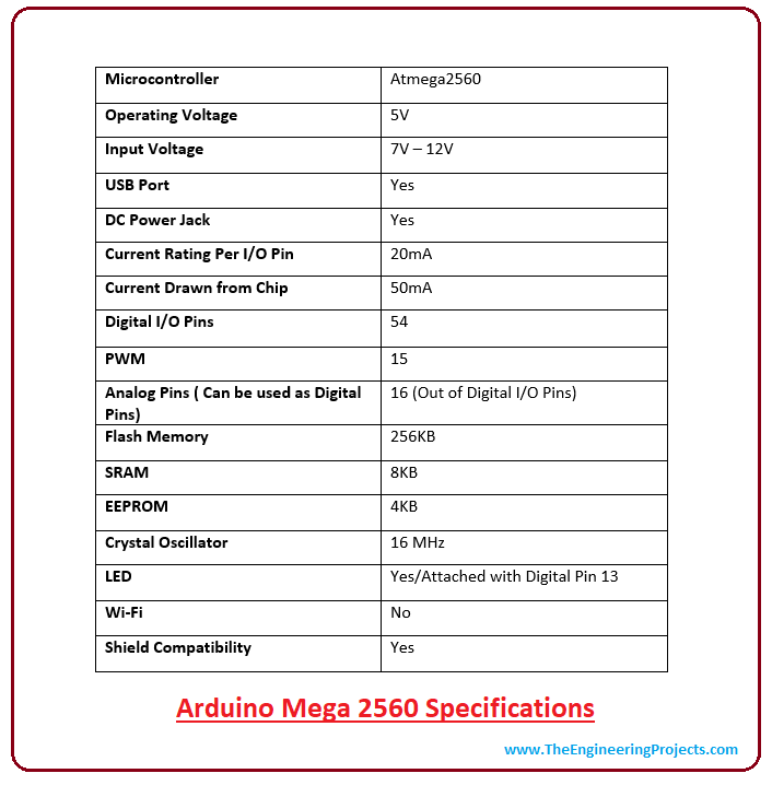
板子参数
引脚与板子说明
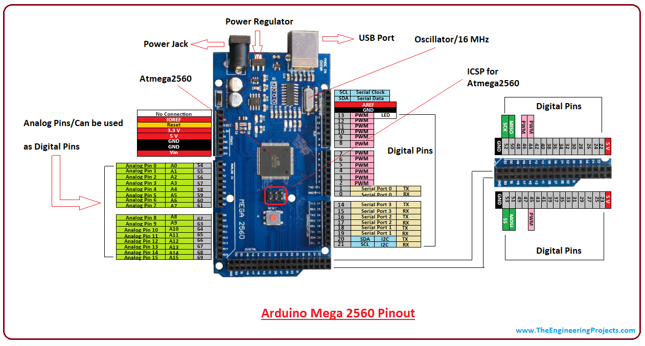
5V & 3.3V 两个对外供电电压
This pin is used to provide output regulated voltage around 5V. This regulated power supply powers up the controller and other components on the board. It can be obtained from Vin of the board or USB cable or another regulated 5V voltage supply. While another voltage regulation is provided by 3.3V pin. Maximum power it can draw is 50mA.
GND 5个电源地
There are 5 ground pins available on the board which makes it useful when more than one ground pins are required for the project.
Reset 复位引脚
This pin is used to reset the board. Setting this pin to LOW will reset the board.
Vin 电源输入引脚,7-12V
It is the input voltage supplied to the board which ranges from 7V to 20V. The voltage provided by the power jack can be accessed through this pin. However, the output voltage through this pin to the board will be automatically set up to 5V.
Serial Communication 串口通信,有4个串口
RXD and TXD are the serial pins used to transmit and receive serial data i.e. Rx represents the transmission of data while Tx used to receive data. There are four combinations of these serial pins are used where Serail 0 contains RX(0) and TX(1), Serial 1 contains TX(18) and RX(19), Serial 2 contains TX(16) and RX(17), and Serial 3 contains TX(14) and RX(15).
External Interrupts 6个外部中断引脚
Six pins are used for creating external interrupts i.e interrupt 0(0), interrupt 1(3), interrupt 2(21), interrupt 3(20), interrupt 4(19), interrupt 5(18). These pins produce interrupts by a number of ways i.e. providing LOW value, rising or falling edge or changing value to the interrupt pins.
LED 一个LED接于13号引脚
This board comes with built-in LED connected to digital pin 13. HIGH value at this pin will turn the LED on and LOW value will turn it off. This gives you the change of nursing your programming skills in real time.
AREF 模拟输入口参考电压
AREF stands for Analog Reference Voltage which is a reference voltage for analog inputs.
Analog Pins 16个模拟量输入引脚(10位的分辨率,对应于0-1024)
There are 16 analog pins incorporated on the board labeled as A0 to A15. It is important to note that all these analog pins can be used as digital I/O pins. Each analog pin comes with 10-bit resolution. These pins can measure from ground to 5V. However, the upper value can be changed using AREF and analogReference() function.
PWM输出口, 14路(8位,对应于0-256)
I2C I2C通信
Two pins 20 and 21 support I2C communication where 20 represents SDA (Serial Data Line mainly used for holding the data) and 21 represents SCL(Serial Clock Line mainly used for providing data synchronization between the devices)
SPI SPI通信
SPI stands for Serial Peripheral Interface used for the transmission of data between the controller and other peripherals components. Four pins i.e. 50 (MISO), 51 (MOSI), 52 (SCK), 53 (SS) are used for SPI communication.
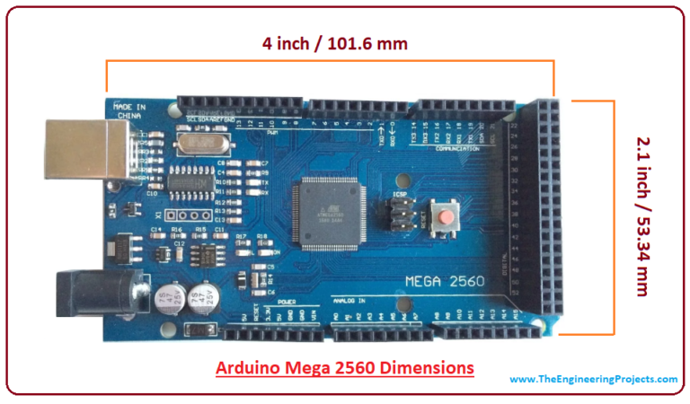
尺寸图
