verilog基础学习
verilog描述模块逻辑
数字逻辑电路以模块(module)的形式定义
语法:
module xxx;


endmodule
标识符的命名规则
1.以字母开头
2.可以包含任何字母和数字以及下划线_、美元符号$
3.区分大小写
verilog模块端口描述
电路模块的端口:一个电路模块有输入和输出信号,它们统称为端口(port)
语法:
module circle(s,x1,x2);//这括号里里面就是端口
input s,x1;
output x2;

endmodule
电路功能描述—门级原始结构
门级原始结构又称门实例化 gate instantiation
语法:
具体哪个门逻辑(output,input,input...)
PS:需要注意的是 有非门的情况先要提前声明,例如not(k,s)
eg:一个2输入与门,其输出为y,输入为x1和x2
and( y, x1, x2 );
电路功能描述—行为定义—连续赋值
在设计大规模电路时,使用门级原始结构会很繁琐。可行的选择是采用更为抽象的表达式和编程结构描述逻辑电路的行为。
所以在这里我们采取用逻辑表达式表示的方法,例如f = ~s1x1 + s1x2
在verilog中就可以用assign 进行连续赋值
assign f = (~s1 & x1) | (s1 & x2)
电路功能描述—行为定义—过程语句
上述是用逻辑表达式定义语句的,这次就来看一个使用过程语句定义的,用always编程结构
eg:如果s=0,则f=x1;如果s=1,则f=x2
if(s) f = x1;
else f = x2;
但是上述过程语句需要包含在always结构中
always @(sensitivity_list)
[begin]
    [procedural assignment statements]  //过程赋值语句
    [if-else statements]  //if-else语句
    [case statements]     //case语句
    [while, repeat, and for loops] //循环语句
    [task and function calls]      //任务和函数调用
[end]
PS:
1.always块中的输出信号必须定义成寄存器型reg
2.一个Verilog模块中可以包含多个always块
3.一整个always块可以看成是一个并行语句
verilog基础练习
Step one
没啥好说的就让你输出一个值
module top_module( output one );

// Insert your code here
    assign one = 1'b1;

endmodule
Zero
也没啥好说的,就是让你指定输出为0
module top_module(
    output zero
);// Module body starts after semicolon
assign zero = 0;
endmodule
Wire
就是让你接线,这里注意输出在左,输入在右
module top_module( input in, output out );
assign out = in;
endmodule
Wire4
也没啥好说的,在一对一接线上,增加了input 的 口
module top_module(
    input a,b,c,
    output w,x,y,z );
	assign w = a;
	assign x = b;
    assign y = b;
    assign z = c;
endmodule
反相器
不在输出端取反,而是将气泡往前推,推到输入端
module top_module( input in, output out );
assign out = ~in;
endmodule
Andgate
没啥好说的,直接在输入端取与即可
module top_module(
    input a,
    input b,
    output out );
assign out = a & b;
endmodule
Norgate
取反往前推,推到输入端
module top_module(
    input a,
    input b,
    output out );
    assign out = ~(a | b);
endmodule
Xnorgate
我其实一开始直接写成与或式,完全忘记了还可以直接用^表示的
module top_module(
    input a,
    input b,
    output out );
    assign out = ~(a ^ b);
endmodule
Wire decl
其实看组合逻辑电路即可
`default_nettype none
module top_module(
    input a,
    input b,
    input c,
    input d,
    output out,
    output out_n   );
    wire haha;
    wire haha1;
    wire haha2;
    assign haha = (a & b);
    assign haha1 = (c & d);
    assign haha2 = (haha|haha1);
    assign out_n = ~haha2;
    assign out = haha2;
endmodule
7458
照样看电路图
module top_module (
    input p1a, p1b, p1c, p1d, p1e, p1f,
    output p1y,
    input p2a, p2b, p2c, p2d,
    output p2y );
    wire p2xi1;
    wire p2xi2;
    wire p1xi1;
    wire p1xi2;
    assign p2xi1 = (p2a & p2b);
    assign p2xi2 = (p2c & p2d);
    assign p2y = (p2xi1 | p2xi2);
    assign p1xi1 = (p1a & p1c & p1b);
    assign p1xi2 = (p1f & p1e & p1d);
    assign p1y = (p1xi1 | p1xi2);

endmodule
Combinational logic
Basic Gate
题目:
Taken from 2015 midterm question 1k

Create a circuit that has two 2-bit inputs A[1:0] and B[1:0], and produces an output z. The value of z should be 1 if A = B, otherwise z should be 0.
这里注意,assign可以像三目运算符语句一般写
module top_module ( input [1:0] A, input [1:0] B, output z );
    assign z = (A == B) ? 1: 0;
endmodule
这样直接写也没有什么问题
assign z = (A[1:0]==B[1:0]);
Mt2015 q4b
题目:
Taken from 2015 midterm question 4

Circuit B can be described by the following simulation waveform:
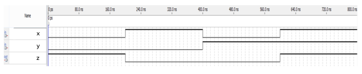
可以从上图观察而出,完全是一个同或图,直接根据公式写即可!
module top_module ( input x, input y, output z );
    assign z = (x & y) | (~x) & (~y);
endmodule
Mt2015 q4
题目:
Taken from 2015 midterm question 4

See mt2015_q4a and mt2015_q4b for the submodules used here. The top-level design consists of two instantiations each of subcircuits A and B, as shown below.
意思让我们将前两个组合成子电路,然后完成下列图片的verilog的编写
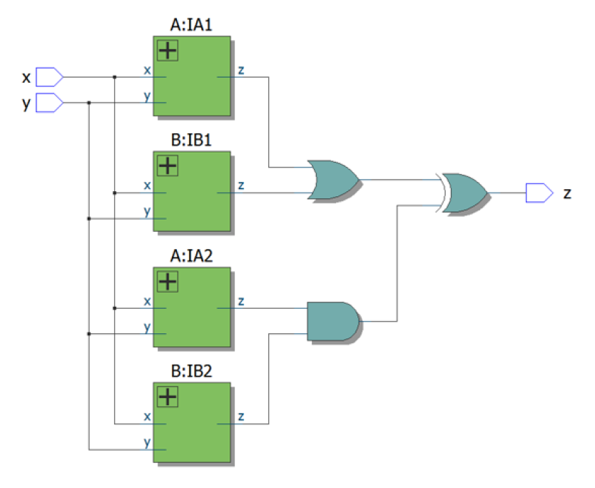
模块化子电路,先将子电路外围的线引出来,标上名字,再对其模块进行封装,封装很简单,只需要 .图中已表示的的(你新取的)的语法即可
module top_module (input x, input y, output z);
	wire za1,za2,zb1,zb2;
    A IA1(.x(x), .y(y), .z(za1));
    A IA2(.x(x), .y(y), .z(za2));

    B IB1(.x(x), .y(y), .z(zb1));
    B IB2(.x(x), .y(y), .z(zb2));
    assign z = (za1 | zb1) ^ (za2 & zb2);
endmodule
module A(x,y,z);
        input x;
        input y;
        output z;
        assign z = (x ^ y) & x;
endmodule

module B(x,y,z);
        input x;
        input y;
        output z;
        assign z = (x & y) | (~x) & (~y);
endmodule
Ringer
题目:
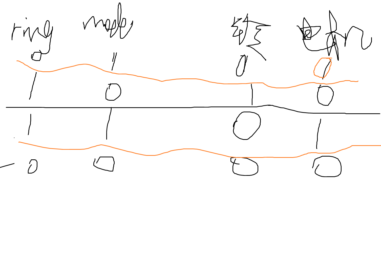
Suppose you are designing a circuit to control a cellphone's ringer and vibration motor. Whenever the phone needs to ring from an incoming call (), your circuit must either turn on the ringer () or the motor (), but not both. If the phone is in vibrate mode (), turn on the motor. Otherwise, turn on the ringer. input ringoutput ringer = 1output motor = 1input vibrate_mode = 1

Try to use only statements, to see whether you can translate a problem description into a collection of logic gates. assign

Design hint: When designing circuits, one often has to think of the problem "backwards", starting from the outputs then working backwards towards the inputs. This is often the opposite of how one would think about a (sequential, imperative) programming problem, where one would look at the inputs first then decide on an action (or output). For sequential programs, one would often think "If (inputs are ___ ) then (output should be ___ )". On the other hand, hardware designers often think "The (output should be ___ ) when (inputs are ___ )".

The above problem description is written in an imperative form suitable for software programming (if ring then do this), so you must convert it to a more declarative form suitable for hardware implementation (). Being able to think in, and translate between, both styles is one of the most important skills needed for hardware design. assign ringer = ___
这玩意就是个文字游戏,我栽坑上了
我栽坑的具体原因就是没考虑到电机会在震动模式下才会震动
我画了个真值表:
module top_module (
    input ring,
    input vibrate_mode,
    output ringer,       // Make sound
    output motor         // Vibrate
);
    assign ringer = (ring == 1 && vibrate_mode == 0) ? 1:0;
    assign motor = (ring == 1 && vibrate_mode == 1)?1:0;
endmodule
Thermostat
还是文字题
module top_module (
    input too_cold,
    input too_hot,
    input mode,
    input fan_on,
    output heater,
    output aircon,
    output fan
);
    assign aircon = (too_hot && ~mode);
    assign heater = (too_cold && mode);
    assign fan = (aircon | heater) | fan_on;
endmodule
Gatesv
题目:
You are given a four-bit input vector in[3:0]. We want to know some relationships between each bit and its neighbour:

out_both: Each bit of this output vector should indicate whether both the corresponding input bit and its neighbour to the left (higher index) are '1'. For example, out_both[2] should indicate if in[2] and in[3] are both 1. Since in[3] has no neighbour to the left, the answer is obvious so we don't need to know out_both[3].
out_any: Each bit of this output vector should indicate whether any of the corresponding input bit and its neighbour to the right are '1'. For example, out_any[2] should indicate if either in[2] or in[1] are 1. Since in[0] has no neighbour to the right, the answer is obvious so we don't need to know out_any[0].
out_different: Each bit of this output vector should indicate whether the corresponding input bit is different from its neighbour to the left. For example, out_different[2] should indicate if in[2] is different from in[3]. For this part, treat the vector as wrapping around, so in[3]'s neighbour to the left is in[0].
直接做即可,注意每一位需要分开来做!
module top_module(
    input [3:0] in,
    output [2:0] out_both,
    output [3:1] out_any,
    output [3:0] out_different );
    	assign out_both[0] = in[0] && in[1];
        assign out_both[1] = in[1] && in[2];
        assign out_both[2] = in[2] && in[3];


        assign out_any[1] = in[1] || in[0];
    	assign out_any[2] = in[2] || in[1];
    	assign out_any[3] = in[3] || in[2];

    	assign out_different[0] = in[0] != in[1];
    	assign out_different[1] = in[1] != in[2];
    	assign out_different[2] = in[2] != in[3];
    	assign out_different[3] = in[3] != in[0];
endmodule
Gatesv100
比上面那题抽象了点,这题用的是循环运算,因为有0-99、0-98位
注:i变量这里不是普通的int类型,而是genvar类型,因为我用了generate
i 被用作循环变量,但它没有被正确声明为 genvar 类型。在 Verilog 中,generate 块中的循环变量必须显式声明为 genvar 类型,而不是普通的 integer 类型。这是因为 genvar 是专门用于 generate 块中的循环变量的
module top_module(
    input [99:0] in,
    output [98:0] out_both,
    output [99:1] out_any,
    output [99:0] out_different );
    genvar i;
	generate
        for(i = 0;i < 99;i = i + 1) begin: obtain_out_both
            assign out_both[i] = in[i] && in[i+1];
        end
    endgenerate

    generate
        for(i = 1;i <= 99;i = i + 1) begin: obtain_out_any
            assign out_any[i] = in[i] || in[i-1];
        end
    endgenerate

     generate
         for(i = 0;i < 100;i = i + 1) begin: obtain_out_different
             assign out_different[i] = in[i] != in[(i+1) % 100];
        end
    endgenerate
endmodule
Multiplexer
Mux2to1
题目:
Create a one-bit wide, 2-to-1 multiplexer. When sel=0, choose a. When sel=1, choose b.
module top_module(
    input a, b, sel,
    output out );
    assign out = (sel && b) || (!sel && a);
endmodule
Mux2to1v
题目:
Create a 100-bit wide, 2-to-1 multiplexer. When sel=0, choose a. When sel=1, choose b.
module top_module(
    input [99:0] a, b,
    input sel,
    output [99:0] out );
	genvar i;
    generate
        for(i = 0;i < 100;i = i + 1) begin : obtain_out
            assign out[i] = (a[i] && !sel) || (b[i] && sel);
        end
    endgenerate
endmodule
Mux9to1v
题目:
Create a 16-bit wide, 9-to-1 multiplexer. sel=0 chooses a, sel=1 chooses b, etc. For the unused cases (sel=9 to 15), set all output bits to '1'.
我写的 sel == 4d'0 ? a 的意思是如果sel == 0000,应该等于a
module top_module(
    input [15:0] a, b, c, d, e, f, g, h, i,
    input [3:0] sel,
    output [15:0] out );
    assign out = (sel == 4'd0) ? a : (sel == 4'd1) ? b:(sel == 4'd2)?c:(sel == 4'd3) ? d:(sel == 4'd4) ? e : (sel == 4'd5)?f:(sel == 4'd6)?g:(sel == 4'd7)?h:(sel == 4'd8)?i:16'hFFFF;
endmodule
Mux256to1
题目:
这题我都没想到这么简单实现了!直接映射到in对应的位即可
如果sel = 0,则in[sel]就是in[0],即in的第0位。
如果sel = 1,则in[sel]就是in[1],即in的第1位。
如果sel = 255,则in[sel]就是in[255],即in的第255位。
Create a 1-bit wide, 256-to-1 multiplexer. The 256 inputs are all packed into a single 256-bit input vector. sel=0 should select in[0], sel=1 selects bits in[1], sel=2 selects bits in[2], etc.
module top_module(
    input [255:0] in,
    input [7:0] sel,
    output out );
    assign out = in[sel];//将in向量中由sel指定的位赋值给输出out。这样就实现了根据sel的值从256个输入中选择一个输出的功能。
endmodule
Mux256to1v
题目:
Create a 4-bit wide, 256-to-1 multiplexer. The 256 4-bit inputs are all packed into a single 1024-bit input vector. sel=0 should select bits in[3:0], sel=1 selects bits in[7:4], sel=2 selects bits in[11:8], etc.
我当时想的就是因为他是四位四位挪动,我就在想如何实现这四位挪动呢,开始想着用循环,后来我发现循环不是那么好实现,于是就用最简单的加乘法实现
sel * 4相当于sel的4位偏移量
+:4 表示从指定的起始位置开始,选择指定长度的位段
module top_module(
    input [1023:0] in,
    input [7:0] sel,
    output [3:0] out );
    assign out = in[(sel * 4) +:4];
endmodule
Arithmentic
Hadd
题目:
hint:与处理进位,异或处理求本来的和
Create a half adder. A half adder adds two bits (with no carry-in) and produces a sum and carry-out.
module top_module(
    input a, b,
    output cout, sum );
	assign sum = a ^ b;
    assign cout = a & b;
endmodule
Fadd
题目:
Create a full adder. A full adder adds three bits (including carry-in) and produces a sum and carry-out.
Fadd
题目:
Create a full adder. A full adder adds three bits (including carry-in) and produces a sum and carry-out.
全加器的进位要一位一位判断,比如 a & b || a & cin || b & cin,不能写到一块去判断!
module top_module(
    input a, b, cin,
    output cout, sum );
    assign cout = a & b | b & cin | a & cin;
    assign sum = a ^ b ^ cin;
endmodule
vector
Vector1
思路:assign 语句的左侧直接写信号名即可,不需要再写范围指定符 [7:0]
module top_module(
    input wire [15:0] in,
    output wire [7:0] out_hi,
    output wire [7:0] out_lo );
    assign out_lo = in[7:0];
    assign out_hi = in[15:8];
endmodule
Vector2
题意说的是将低位跟高位交换,直接赋值即可
module top_module(
    input [31:0] in,
    output [31:0] out );//
    assign out[31:24] = in[7:0];
    assign out[23:16] = in[15:8];
    assign out[15:8] = in[23:16];
    assign out[7:0] = in[31:24];
    // assign out[31:24] = ...;

endmoduleVector2
题意说的是将低位跟高位交换,直接赋值即可
Vector3
位拼接
注意点: 拼接的顺序是从左到右,左边的信号位于拼接结果的高位,右边的信号位于拼接结果的低位
我开始的时候将直接从低位开始取,没想到答案出来是从高位往低位取的!!
module top_module (
    input [4:0] a, b, c, d, e, f,
    output [7:0] w, x, y, z );//

    // assign { ... } = { ... };
    assign w = {a[4:0],b[4:2]};
    assign x = {b[1:0],c,d[4]};
    assign y = {d[3:0],e[4:1]};
    assign z = {e[0],f,2'b11};
endmodule
Vectorr
题目:
Given an 8-bit input vector [7:0], reverse its bit ordering.
我的办法就是看这位数挺少的直接一位位翻转即可!
module top_module(
    input [7:0] in,
    output [7:0] out
);
    assign out[0] = in[7];
    assign out[1] = in[6];
    assign out[2] = in[5];
    assign out[3] = in[4];
    assign out[4] = in[3];
    assign out[5] = in[2];
    assign out[6] = in[1];
    assign out[7] = in[0];
endmodule
Vector4
题目:
A Bit of Practice
One common place to see a replication operator is when sign-extending a smaller number to a larger one, while preserving its signed value. This is done by replicating the sign bit (the most significant bit) of the smaller number to the left. For example, sign-extending 4'b0101 (5) to 8 bits results in 8'b00000101 (5), while sign-extending 4'b1101 (-3) to 8 bits results in 8'b11111101 (-3).

Build a circuit that sign-extends an 8-bit number to 32 bits. This requires a concatenation of 24 copies of the sign bit (i.e., replicate bit[7] 24 times) followed by the 8-bit number itself.
思路:
assign out = {{24{in[7]}}, in};这一句足矣,让我来解释一下
24{in[7]} 的意思是 把符号位复制24次
{{24{in[7]},in} 将复制的符号位和原始输入信号拼接起来,形成完整的32位输出信号
module top_module (
    input [7:0] in,
    output [31:0] out );//

    // assign out = { replicate-sign-bit , the-input };
    assign out = {{24{in[7]}},in};
endmodule
Vector5
题目:
As the diagram shows, this can be done more easily using the replication and concatenation operators.

The top vector is a concatenation of 5 repeats of each input
The bottom vector is 5 repeats of a concatenation of the 5 inputs
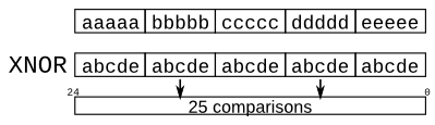
其实就让你延续上一个题的思想拼装,只是题目让你一个个 位去比较,上面一行就分别用5个a,5个b,5个c依此类推封装,而下一行就用5个abcde封装即可
module top_module (
    input a, b, c, d, e,
    output [24:0] out );//

    // The output is XNOR of two vectors created by
    // concatenating and replicating the five inputs.
    // assign out = ~{ ... } ^ { ... };
    wire [24:0] wire1 = {{5{a}},{5{b}},{5{c}},{5{d}},{5{e}}};
    wire [24:0] wire2 = {{5{a,b,c,d,e}}};
    assign out = ~(wire1 ^ wire2);
endmodule
Module
第一个模块化编程:有两种方式来进行电路连接,一个是 位置,一个是直接命名(类似函数传参思想,不过这个比较麻烦,模块的端口列表发生更改,还需要找到并更改模块的所有实例以匹配新模块) 所有默认我们用第一种方式
By position
通过位置将电线连接到端口的语法应该很熟悉,因为它使用类似C的语法。实例化模块时,根据模块的声明从左到右连接端口。
例如:mod_a instance1 (wa,wb,wc);这将实例化类型为mod_a的模块,并为其提供实例名称“ instance1”,然后将信号wa(在新模块之外)连接到新模块的第一个端口(in1),将wb连接到第二个端口(in2),然后wc到第三个端口(out)。
这种语法的一个缺点是,如果模块的端口列表发生更改,则还需要找到并更改模块的所有实例以匹配新模块。

By name
通过名称将信号连接到模块的端口,即使端口列表发生更改,也可以保持电线正确连接。但是,此语法更为冗长。
例如:mod_a instance2 ( .out(wc), .in1(wa), .in2(wb) );这实例化了一个名为“ instance2”的mod_a类型的模块,然后将信号wa(在模块外部)连接到名为in1的端口,将wb连接到名为in2的端口,并将wc连接到名为out的端口。
请注意,此处的端口顺序无关紧要,因为将以正确的名称进行连接,而不管其在子模块的端口列表中的位置如何。还要注意此语法中端口名称前的句点。
module top_module ( input a, input b, output out );
    mod_a instance2(.out(out), .in1(a), .in2(b));
endmodule
Module pos
跟前一题类似,不过这次 a module named mod_a that has 2 outputs and 4 inputs,而且是位置赋值,直接用输入输出值代替即可
module top_module (
    input a,
    input b,
    input c,
    input d,
    output out1,
    output out2
);
    mod_a instance2(out1,out2,a,b,c,d);
endmodule
Module name
这次是名字命名,直接写!
module top_module (
    input a,
    input b,
    input c,
    input d,
    output out1,
    output out2
);
    mod_a instance2(.out1(out1), .out2(out2), .in1(a), .in2(b), .in3(c), .in4(d));
endmodule
Module shift
按照D触发器的原理即可写出,注意q和d对应状态对应的电线
module top_module ( input clk, input d, output q );
    wire q1_wire;
    wire q2_wire;
    my_dff instance1(.clk(clk), .d(d), .q(q1_wire));
    my_dff instance2(.clk(clk), .d(q1_wire), .q(q2_wire));
    my_dff instance3(.clk(clk), .d(q2_wire), .q(q));
endmodule
Module add
抽象!!!两个加法器,高16位和低16位进行存储,再合并输出
module top_module(
    input [31:0] a,
    input [31:0] b,
    output [31:0] sum
);
    wire [15:0] sum1,sum2;
    wire cin;
    wire cout1,cout2;
    assign cin = 1'b0;
    add16 instance0(.a(a[15:0]), .b(b[15:0]), .cin(cin), .sum(sum1), .cout(cout1));
    add16 instance1(.a(a[31:16]),.b(b[31:16]),.cin(cout1),.sum(sum2),.cout(cout2));
    assign sum = {sum2,sum1};//注意这里是高位-低位合并,不能随便乱换位置!!!!
endmodule
本文来自博客园,作者:Alaso_shuang,转载请注明原文链接:https://www.cnblogs.com/Alaso687/p/18980291

 浙公网安备 33010602011771号