[模拟电路] 2、Passive Band Pass Filter
note: Some articles are very good in http://www.electronics-tutorials.ws/,I share them in the Cnblog so that Chinese hardware engineers can enjoy and learn.
The cut-off frequency or ƒc point in a simple RC passive filter can be accurately controlled using just a single resistor in series with a non-polarized(非极性) capacitor, and depending upon which way around they are connected, we have seen that either a Low Pass or a High Pass filter is obtained.
One simple use for these types of passive filters is in audio amplifier applications or circuits such as in loudspeaker crossover filters(扬声器分频滤波器) or pre-amplifier tone controls(前置放大器音色控制). Sometimes it is necessary to only pass a certain range of frequencies that do not begin at 0Hz, (DC) or end at some upper high frequency point but are within a certain range or band of frequencies, either narrow or wide.
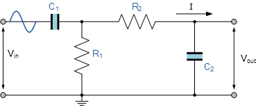
By connecting or “cascading” together(连接或级联) a single Low Pass Filter circuit with a High Pass Filter circuit, we can produce another type of passive RC filter that passes a selected range or “band” of frequencies that can be either narrow or wide while attenuating all those outside of this range. This new type of passive filter arrangement produces a frequency selective filter known commonly as a Band Pass Filter or BPF for short.
Band Pass Filter Circuit

Unlike a low pass filter that only pass signals of a low frequency range or a high pass filter which pass signals of a higher frequency range, a Band Pass Filters passes signals within a certain “band” or “spread” of frequencies without distorting(扭曲) the input signal or introducing(引入) extra noise. This band of frequencies can be any width and is commonly known as the filters Bandwidth.
Then for widely spread frequencies, we can simply define the term “bandwidth”, BW as being the difference between the lower cut-off frequency ( ƒcLOWER ) and the higher cut-off frequency ( ƒcHIGHER ) points. In other words, BW = ƒH – ƒL. Clearly for a pass band filter to function correctly, the cut-off frequency of the low pass filter must be higher than the cut-off frequency for the high pass filter.
The “ideal” Band Pass Filter(理想带通滤波器) can also be used to isolate or filter out(隔离或滤除) certain frequencies that lie within a particular(特定的) band of frequencies, for example, noise cancellation(噪声消除). Band pass filters are known generally as second-order(二阶) filters, (two-pole) because they have “two” reactive component(活性原件), the capacitors, within their circuit design. One capacitor in the low pass circuit and another capacitor in the high pass circuit.
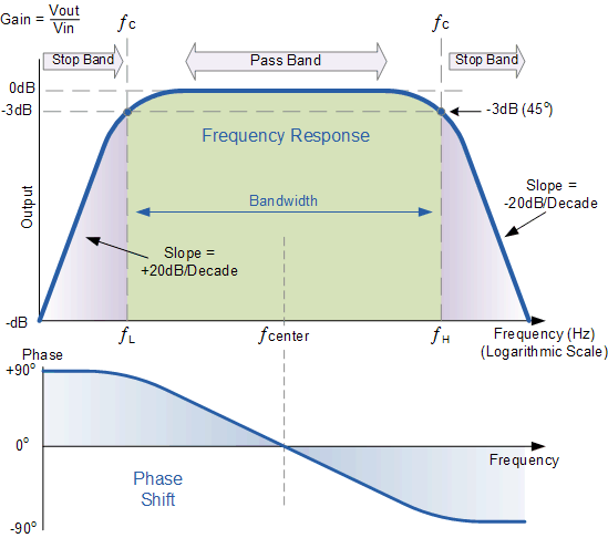
Frequency Response of a 2nd Order Band Pass Filter.

The Bode Plot(波特图) or frequency response curve(频率响应曲线) above shows the characteristics of the band pass filter. Here the signal is attenuated(衰减) at low frequencies with the output increasing at a slope of +20dB/Decade (6dB/Octave)(随着+20dB/Decade的坡度衰减)until the frequency reaches the “lower cut-off” point ƒL. At this frequency the output voltage is again 1/√2 = 70.7% of the input signal value or -3dB (20 log (Vout/Vin)) of the input.
The output continues at maximum gain(增益) until it reaches the “upper cut-off” point ƒHwhere the output decreases at a rate of -20dB/Decade (6dB/Octave) attenuating any high frequency signals. The point of maximum output gain is generally the geometric mean of the two -3dB value between the lower and upper cut-off points(最大输出增益点一般是两个在最低和最高截止点之间值为-3dB的频率的几何平均) and is called the “Centre Frequency” or “Resonant Peak(共振峰)” value ƒr. This geometric mean value is calculated as being ƒr 2 = ƒ(UPPER) x ƒ(LOWER).
A band pass filter is regarded as a second-order (two-pole) type filter because it has “two” reactive components within its circuit structure, then the phase angle will be twice that of the previously seen first-order filters, ie, 180o. The phase angle of the output signal LEADS that of the input by +90o up to the centre or resonant frequency, ƒrpoint were it becomes “zero” degrees (0o) or “in-phase” and then changes to LAG the input by -90o as the output frequency increases.
The upper and lower cut-off frequency points for a band pass filter can be found using the same formula(公式) as that for both the low and high pass filters, For example.

Then clearly, the width of the pass band of the filter can be controlled by the positioning of the two cut-off frequency points of the two filters.
Band Pass Filter Example No1.
A second-order band pass filter is to be constructed using RC components that will only allow a range of frequencies to pass above 1kHz (1,000Hz) and below 30kHz (30,000Hz). Assuming that both the resistors have values of 10kΩ´s, calculate the values of the two capacitors required.
The High Pass Filter Stage.
The value of the capacitor C1 required to give a cut-off frequency ƒL of 1kHz with a resistor value of 10kΩ is calculated as:

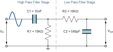
Then, the values of R1 and C1 required for the high pass stage to give a cut-off frequency of 1.0kHz are: R1 = 10kΩ´s and C1 = 15nF.
The Low Pass Filter Stage.
The value of the capacitor C2 required to give a cut-off frequency ƒH of 30kHz with a resistor value of 10kΩ is calculated as:

Then, the values of R2 and C2 required for the low pass stage to give a cut-off frequency of 30kHz are, R = 10kΩ´s and C = 510pF. However, the nearest preferred value of the calculated capacitor value of 510pF is 560pF so this is used instead.
With the values of both the resistances R1 and R2 given as 10kΩ, and the two values of the capacitors C1 and C2 found for both the high pass and low pass filters as 15nF and 560pF respectively, then the circuit for our simple passive Band Pass Filter is given as.
Completed Band Pass Filter Circuit

Band Pass Filter Resonant Frequency
We can also calculate the “Resonant” or “Centre Frequency” (ƒr) point of the band pass filter were the output gain is at its maximum or peak value. This peak value is not the arithmetic average of the upper and lower -3dB cut-off points as you might expect but is in fact the “geometric” or mean value. This geometric mean value is calculated as being ƒr 2 = ƒc(UPPER) x ƒc(LOWER) for example:
Centre Frequency Equation

- Where, ƒr is the resonant or centre frequency
- ƒL is the lower -3dB cut-off frequency point
- ƒH is the upper -3db cut-off frequency point
and in our simple example above, the calculated cut-off frequencies were found to be ƒL= 1,060 Hz and ƒH = 28,420 Hz using the filter values.
Then by substituting these values into the above equation gives a central resonant frequency of:

Band Pass Filter Summary
A simple passive Band Pass Filter can be made by cascading together a single Low Pass Filter with a High Pass Filter. The frequency range, in Hertz, between the lower and upper -3dB cut-off points of the RC combination is know as the filters “Bandwidth”.
The width or frequency range of the filters bandwidth can be very small and selective, or very wide and non-selective depending upon the values of R and C used.
The centre or resonant frequency point is the geometric mean of the lower and upper cut-off points. At this centre frequency the output signal is at its maximum and the phase shift of the output signal is the same as the input signal.
The amplitude of the output signal from a band pass filter or any passive RC filter for that matter, will always be less than that of the input signal. In other words a passive filter is also an attenuator giving a voltage gain of less than 1 (Unity). To provide an output signal with a voltage gain greater than unity, some form of amplification is required within the design of the circuit.(无源带通滤波器输出小于输入,想要增益大于1的带通滤波器就要设计一种新的电路了)
A Passive Band Pass Filter is classed as a second-order type filter because it has two reactive components within its design, the capacitors. It is made up from two single RC filter circuits that are each first-order filters themselves.
If more filters are cascaded together the resulting circuit will be known as an “nth-order” filter where the “n” stands for the number of individual reactive components and therefore poles within the filter circuit. For example, filters can be a 2nd-order, 4th-order, 10th-order, etc.
The higher the filters order the steeper will be the slope(斜率) at n times -20dB/decade. However, a single capacitor value made by combining together two or more individual capacitors is still one capacitor.
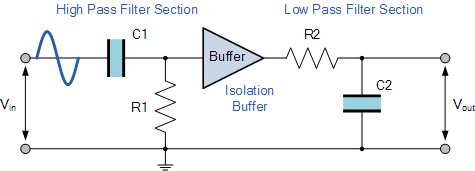
Our example above shows the output frequency response curve for an “ideal” band pass filter with constant gain in the pass band and zero gain in the stop bands. In practice(实际中) the frequency response of this Band Pass Filter circuit would not be the same as the input reactance of the high pass circuit would affect the frequency response of the low pass circuit (components connected in series or parallel组件的串并联) and vice versa(高通滤波器的输入电抗将会影响低通滤波器的频率响应,反之亦然). One way of overcoming this would be to provide some form of electrical isolation(隔离) between the two filter circuits as shown below.
Buffering Individual Filter Stages

One way of combining amplification and filtering into the same circuit would be to use an Operational Amplifier or Op-amp, and examples of these are given in the Operational Amplifier section. In the next tutorial we will look at filter circuits which use an operational amplifier within their design to not only to introduce gain but provide isolation between stages. These types of filter arrangements are generally known as Active Filters.
@beautifulzzzz
智能硬件、物联网,热爱技术,关注产品
博客:http://blog.beautifulzzzz.com
sina:http://weibo.com/beautifulzzzz?is_all=1


 浙公网安备 33010602011771号