

实验19:Frame-Relay
实验16-1. 帧中继多点子接口
Ø 实验目的
通过本实验,读者可以掌握如下技能:
(1) 帧中继的基本配置
(2) 帧中继的静态映射
(3) 多点子接口的应用
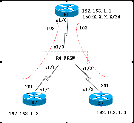
Ø 实验拓扑
实验步骤
n 步骤1:配置R4模拟FRSW
R4(config)#no ip routing
R4(config)#frame-relay switching
//启用帧中继交换
R4(config)#int s1/0
R4(config-if)#no sh
R4(config-if)#encapsulation frame-relay
R4(config-if)#frame-relay intf-type dce
R4(config-if)#clock rate 64000
R4(config-if)#frame-relay lmi-type cisco
R4(config-if)#frame-relay route 102 interface s1/1 201
R4(config-if)#frame-relay route 103 interface s1/2 301
//配置帧中继路由
R4(config)#int s1/1
R4(config-if)#no sh
R4(config-if)#encapsulation frame-relay
R4(config-if)#frame-relay lmi-type cisco
R4(config-if)#clock rate 64000
R4(config-if)#frame-relay intf-type dce
R4(config-if)#frame-relay route 201 interface s1/0 102
R4(config)#int s1/2
R4(config-if)#no sh
R4(config-if)#encapsulation frame-relay
R4(config-if)#frame-relay lmi-type cisco
R4(config-if)#clock rate 64000
R4(config-if)#frame-relay intf-type dce
R4(config-if)#frame-relay route 301 interface s1/0 103
n 步骤2: DTE的配置
R1(config)#int s1/0
R1(config-if)#no ip address //主接口下不需要IP 地址
R1(config-if)#encap frame-relay //封装帧中继
R1(config-if)#no frame-relay inverse-arp //关闭自动映射
R1(config-if)#no shut
R1(config)#int s1/0.2 multipoint //创建点到多点子接口
R1(config-subif)#ip add 192.168.1.1 255.255.255.0
R1(config-subif)#frame-relay map ip 192.168.1.2 102 broadcast
R1(config-subif)#frame-relay map ip 192.168.1.3 103 broadcast
//配置帧中继映射
【提示】可以使用“no interface s1/0.2”命令来删除子接口,然而需要重新启动路由器,该子接口才真正被删除。
R1(config-if)#frame-relay lmi-type cisco
//如果采用的是cisco 路由器且IOS 是11.2 及以后版本的,路由器可以自动适应LMI 的类型,则本步骤可不做。国内帧中继线路一般采用ansi 的LMI 信令类型,我们这里采用的是cisco。
R2(config)#int s1/1
R2(config-if)#ip address 192.168.1.2 255.255.255.0
R2(config-if)#encapsulation frame-relay
R2(config-if)#no shutdown
R2(config-if)#no frame-relay inverse-arp //关闭自动映射
R2(config-if)#frame-relay map ip 192.168.1.1 201 broadcast
R3(config)#int s1/2
R3(config-if)#ip address 192.168.1.3 255.255.255.0
R3(config-if)#encapsulation frame-relay
R3(config-if)#no shutdown
R3(config-if)#no frame-relay inverse-arp //关闭自动映射
R3(config-if)#frame-relay map ip 192.168.1.1 301 broadcast
n 步骤3:测试连通性
从各个路由器ping 其他路由器:
R1#ping 192.168.1.2
Type escape sequence to abort.
Sending 5, 100-byte ICMP Echos to 192.168.1.2, timeout is 2 seconds:
!!!!!
Success rate is 100 percent (5/5), round-trip min/avg/max = 8/34/84 ms
R1#ping 192.168.1.3
Type escape sequence to abort.
Sending 5, 100-byte ICMP Echos to 192.168.2.3, timeout is 2 seconds:
!!!!!
Success rate is 100 percent (5/5), round-trip min/avg/max = 4/27/96 ms
Ø 实验调试
可以使用“show frame-relay map”、“show frame pvc”、“show frame lmi”等命令检查帧中继交换机是否正常
R1#show frame-relay map
Serial1/0.2 (up): ip 192.168.1.2 dlci 102(0x66,0x1860), static,
broadcast,
CISCO, status defined, active
Serial1/0.2 (up): ip 192.168.1.3 dlci 103(0x67,0x1870), static,
broadcast,
CISCO, status defined, active
从命令输出中可以得到的信息有:
n 192.168.1.2 映射到102
n Static:表明是静态手工的
n Broadcast:该PVC 允许广播包的通过
n Active:该PVC 是激活的
该命令是很重要的一条命令,如果在映射表中不存在映射,路由器将无法通信。可以使用名命令“clear frame-relay inarp”命令清除无效的帧中继映射表。
R1#show frame-relay pvc
PVC Statistics for interface Serial1/0 (Frame Relay DTE)
Active Inactive Deleted Static
Local 2 0 0 0
Switched 0 0 0 0
Unused 4 0 0 0
DLCI = 102, DLCI USAGE = LOCAL, PVC STATUS = ACTIVE, INTERFACE = Serial1/0.2
input pkts 15 output pkts 15 in bytes 1560
out bytes 1560 dropped pkts 0 in pkts dropped 0
out pkts dropped 0 out bytes dropped 0
in FECN pkts 0 in BECN pkts 0 out FECN pkts 0
out BECN pkts 0 in DE pkts 0 out DE pkts 0
out bcast pkts 0 out bcast bytes 0
5 minute input rate 0 bits/sec, 0 packets/sec
5 minute output rate 0 bits/sec, 0 packets/sec
pvc create time 00:15:23, last time pvc status changed 00:14:23
DLCI = 103, DLCI USAGE = LOCAL, PVC STATUS = ACTIVE, INTERFACE = Serial1/0.2
input pkts 21 output pkts 30 in bytes 2114
out bytes 3120 dropped pkts 0 in pkts dropped 0
out pkts dropped 0 out bytes dropped 0
in FECN pkts 0 in BECN pkts 0 out FECN pkts 0
out BECN pkts 0 in DE pkts 0 out DE pkts 0
out bcast pkts 0 out bcast bytes 0
5 minute input rate 0 bits/sec, 0 packets/sec
5 minute output rate 0 bits/sec, 0 packets/sec
pvc create time 00:15:35, last time pvc status changed 00:14:35
从命令输出中可以得到的信息有:
n DLCI = 102:表明该PVC 的DLCI 为102
n PVC STATUS = ACTIVE:表明PVC 的状态是激活的;若PVC STATUS = INACTIVE—表明远端路由器没正确配置;若PVC STATUS = DELETED—表明输入了错误的DLCI,该PVC 不存在。
R1#show frame-relay lmi
LMI Statistics for interface Serial1/0(Frame Relay DTE) LMI TYPE = ANSI
Invalid Unnumbered info 0 Invalid Prot Disc 0
Invalid dummy Call Ref 0 Invalid Msg Type 0
Invalid Status Message 0 Invalid Lock Shift 0
Invalid Information ID 0 Invalid Report IE Len 0
Invalid Report Request 0 Invalid Keep IE Len 0
Num Status Enq. Sent 103 Num Status msgs Rcvd 104
Num Update Status Rcvd 0 Num Status Timeouts 0
Last Full Status Req 00:00:17 Last Full Status Rcvd 00:00:17
从命令输出中可以得到的信息有:
n LMI TYPE = ANSI:表明帧中继LMI 类型为ANSI;
n Frame Relay DTE:这是帧中继DTE
n Num Status Enq. Sent 103:表明路由器向帧中继交换机发送的LMI 状态查询消息的数量;
n Num Status msgs Rcvd 104:表明路由器从帧中继交换机收到的LMI 状态信息数量
【提示】
在R1,R2,R3上运行RIP ,在R2上添加回环接口并宣告网段,在R3上查看是否能学到该网段
R2(config-if)#int lo0
R2(config-if)#ip add 2.2.2.2 255.255.255.0
R2(config)#router rip
R2(config-router)#net 2.0.0.0
注意:如果路由协议运行RIP,封装Frame-relay的物理接口默认关闭水平分割,multipoint默认启用水平分割
R3#show ip route
Codes: C - connected, S - static, R - RIP, M - mobile, B - BGP
D - EIGRP, EX - EIGRP external, O - OSPF, IA - OSPF inter area
N1 - OSPF NSSA external type 1, N2 - OSPF NSSA external type 2
E1 - OSPF external type 1, E2 - OSPF external type 2
Gateway of last resort is not set
R 2.0.0.0/8 [120/1] via 192.168.2.1, 00:00:47, Serial1/2
C 192.168.1.0/24 is directly connected, Serial1/2
实验16-2:帧中继点到点子接口
Ø 实验目的
通过本实验,读者可以掌握点到点子接口的配置
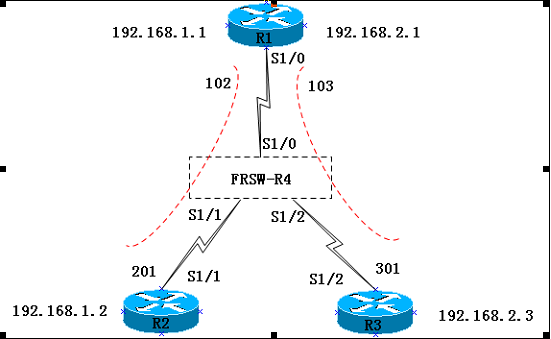
Ø 实验拓扑
实验步骤
n 步骤1:R1配置如下
R1(config)#interface serial1/0
R1(config-if)#no ip address
R1(config-if)#encap frame-relay
R1(config-if)#no frame-relay inverse-arp
R1(config-if)#no shutdown
R1(config)#int s1/0.2 point-to-point //创建点到点子接口
R1(config-subif)#ip address 192.168.1.1 255.255.255.0
R1(config-subif)#frame-relay interface-dlci 102
R1(config)#int s1/0.3 point-to-point
R1(config-subif)#ip address 192.168.2.1 255.255.255.0
R1(config-subif)#frame-relay interface-dlci 103
R1(config)#int lo0
R1(config-if)#ip add 1.1.1.1 255.255.255.0
R1(config)#router rip
R1(config-router)#network 1.0.0.0
R1(config-router)#network 192.168.1.0
R1(config-router)#network 192.168.2.0
n 步骤2:R2配置如下:
R2(config)#interface serial 1/1
R2(config-if)#no ip address
R2(config-if)#encapsulation frame-relay
R2(config-if)#no frame-relay inverse-arp
R2(config-if)#no shutdown
R2(config-if)#exit
R2(config)#int s1/1.1 point-to-point
R2(config-subif)#ip address 192.168.1.2 255.255.255.0
R2(config-subif)#frame-relay interface-dlci 201
R2(config-subif)#exit
R2(config)#int lo0
R2(config-if)#ip add 2.2.2.2 255.255.255.0
R2(config)#router rip
R2(config-router)#network 2.0.0.0
R2(config-router)#network 192.168.1.0
n 步骤3:R3配置如下:
R3(config)#interface serial 1/2
R3(config-if)#no ip address
R3(config-if)#encapsulation frame-relay
R3(config-if)#no frame-relay inverse-arp
R3(config-if)#no shutdown
R3(config-if)#exit
R3(config)#interface serial 1/2.1 point-to-point
R3(config-subif)#ip address 192.168.2.3 255.255.255.0
R3(config-subif)#frame-relay interface-dlci 301
R3(config-subif)#exit
R3(config)#int lo0
R3(config-if)#ip add 3.3.3.3 255.255.255.0
R3(config)#router rip
R3(config-router)#network 3.0.0.0
R3(config-router)#network 192.168.2.0
Ø 实验调试
在各个路由器上检查路由表,注意路由的下一跳。
R3#show ip route
R3#show ip rou
Codes: C - connected, S - static, R - RIP, M - mobile, B - BGP
D - EIGRP, EX - EIGRP external, O - OSPF, IA - OSPF inter area
N1 - OSPF NSSA external type 1, N2 - OSPF NSSA external type 2
E1 - OSPF external type 1, E2 - OSPF external type 2
i - IS-IS, su - IS-IS summary, L1 - IS-IS level-1, L2 - IS-IS level-2
ia - IS-IS inter area, * - candidate default, U - per-user static route
o - ODR, P - periodic downloaded static route
Gateway of last resort is not set
R 1.0.0.0/8 [120/1] via 192.168.2.1, 00:00:02, Serial1/2.1
R 2.0.0.0/8 [120/1] via 192.168.2.1, 00:00:02, Serial1/2.1
3.0.0.0/24 is subnetted, 1 subnets
C 3.3.3.0 is directly connected, Loopback0
R 192.168.1.0/24 [120/1] via 192.168.2.1, 00:00:02, Serial1/2.1
C 192.168.2.0/24 is directly connected, Serial1/2.1

 浙公网安备 33010602011771号