
【转】边沿检测
Abstract
邊緣檢測電路(edge detection circuit)是個常見的基本電路。
Introduction
使用環境:Quartus II 7.2 SP3
所謂的邊緣檢測,簡單的說就是判斷前一個clock的狀態和目前clock狀態的比較,若由0變1,就是上升沿檢測電路(posedge edge detection circuit)(又稱上緣微分電路),若是由1變0,就是下升沿檢測電路(negedge edge detection circuit)(又稱下緣微分電路),若上升沿與下升沿都要檢測,就是雙沿檢測電路電路(double edge detection)。
上升沿檢測電路(posedge detection circuit)
Method 1:
使用兩個reg
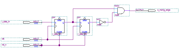
r_data_in0與r_data_in1為D-FF,分別hold住上一個clock與目前clock的i_data_in,所謂上升沿電路,就是i_data_in由0變1,也就是r_data_in0為0且r_data_in1為1,故用not接r_data_in0,之後再用and連接r_data_in1。
posedge_detection.v / Verilog
- /*
- (C) OOMusou 2008 http://oomusou.cnblogs.com
-
- Filename : posedge_detection.v
- Compiler : Quartus II 7.2 SP3
- Description : Demo how to design posedge detection circuit
- Release : 07/06/2008 1.0
- */
-
- module posedge_detection (
- input clk,
- input rst_n,
- input i_data_in,
- output o_rising_edge
- );
-
- reg r_data_in0;
- reg r_data_in1;
-
- assign o_rising_edge = ~r_data_in0 & r_data_in1;
-
- always@(posedge clk, negedge rst_n) begin
- if (!rst_n) begin
- r_data_in0 <= 0;
- r_data_in1 <= 0;
- end
- else begin
- r_data_in0 <= r_data_in1;
- r_data_in1 <= i_data_in;
- end
- end
-
- endmodule
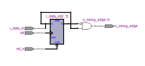
這種寫法經過合成後,會很聰明的只用一個2 bit的D-FF,與一個AND。
Method 2:
使用1個reg
posedge_edgedetection2.v / Verilog
2 (C) OOMusou 2008 http://oomusou.cnblogs.com
3
4 Filename : posedge_detection2.v
5 Compiler : Quartus II 7.2 SP3
6 Description : Demo how to design posedge detection circuit
7 Release : 08/11/2008 1.0
8 */
9
10 module posedge_detection2 (
11 input clk,
12 input rst_n,
13 input i_data_in,
14 output reg o_rising_edge
15 );
16
17 reg r_data_in0;
18
19 always@(posedge clk, negedge rst_n) begin
20 if (!rst_n)
21 r_data_in0 <= 0;
22 else begin
23 r_data_in0 <= i_data_in;
24
25 if ({r_data_in0, i_data_in} == 2'b01)
26 o_rising_edge <= 1;
27 else
28 o_rising_edge <= 0;
29 end
30 end
31
32 endmodule
若你覺得Method 1比較不好理解,那Method 2就非常的behavior,只使用一個reg記住前一個clock的狀態,並在這個clock判斷前一個狀態是否為0且目前狀態是否為1,這樣就是posedge了。
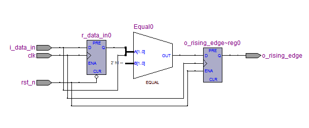
這種寫法經過合成之後,只有一個D-FF與EQUAL,右邊的o_rising_edge的D-FF主要是因為在always block內的reg。
就這個例子而言,Method 1與Method 2目前在Quartus II 7.2 SP3的合成下resource打成平手,logic element各用兩個D-FF與與一個組合電路,不過Method 2的code可讀性比較高。

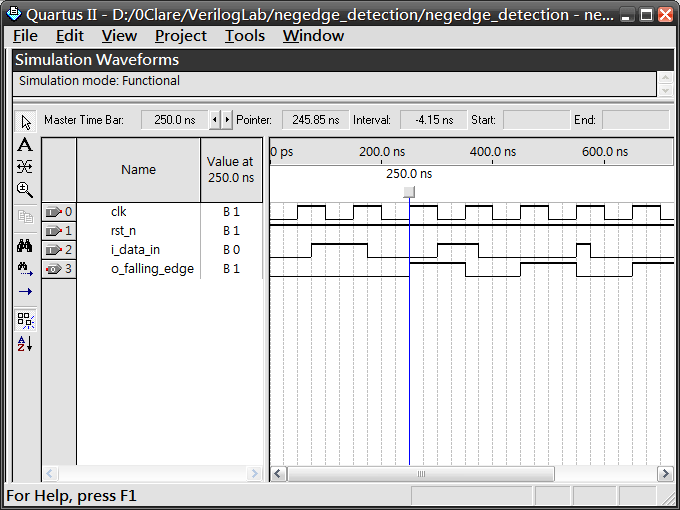
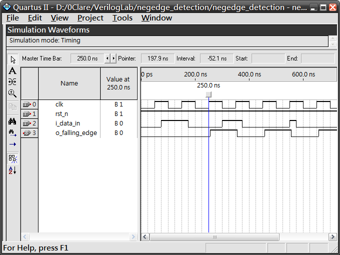
下升沿檢測電路(negedge detection circuit)
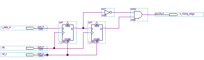
r_data_in2與r_data_in1為reg,分別hold住上一個clock與目前clock的i_data_in,所謂下升沿電路,就是i_data_in由1變0,也就是r_data_in2為1且r_data_in1為0,故用not接r_data_in1,之後再用and連接r_data_in2。
Method 1:
使用兩個reg
nededge_detection.v / Verilog
- /*
- (C) OOMusou 2008 http://oomusou.cnblogs.com
-
- Filename : nededge_detection.v
- Compiler : Quartus II 7.2 SP3
- Description : Demo how to design nededge detection circuit
- Release : 07/06/2008 1.0
- */
- module negedge_detection (
- input clk,
- input rst_n,
- input i_data_in,
- output o_falling_edge
- );
-
- reg r_data_in0;
- reg r_data_in1;
-
- assign o_falling_edge = r_data_in0 & ~r_data_in1;
-
- always@(posedge clk, negedge rst_n) begin
- if (!rst_n) begin
- r_data_in0 <= 0;
- r_data_in1 <= 0;
- end
- else begin
- r_data_in0 <= r_data_in1;
- r_data_in1 <= i_data_in;
- end
- end
-
- endmodule
Method 2:
使用1個reg
nededge_detection2.v
2 (C) OOMusou 2008 http://oomusou.cnblogs.com
3
4 Filename : nededge_detection2.v
5 Compiler : Quartus II 7.2 SP3
6 Description : Demo how to design nededge detection circuit
7 Release : 07/06/2008 1.0
8 */
9 module negedge_detection2 (
10 input clk,
11 input rst_n,
12 input i_data_in,
13 output reg o_falling_edge
14 );
15
16 reg r_data_in0;
17
18 always@(posedge clk, negedge rst_n) begin
19 if (!rst_n)
20 r_data_in0 <= 0;
21 else begin
22 r_data_in0 <= i_data_in;
23
24 if ({r_data_in0, i_data_in} == 2'b10)
25 o_falling_edge <= 1;
26 else
27 o_falling_edge <= 0;
28 end
29 end
30
31 endmodule
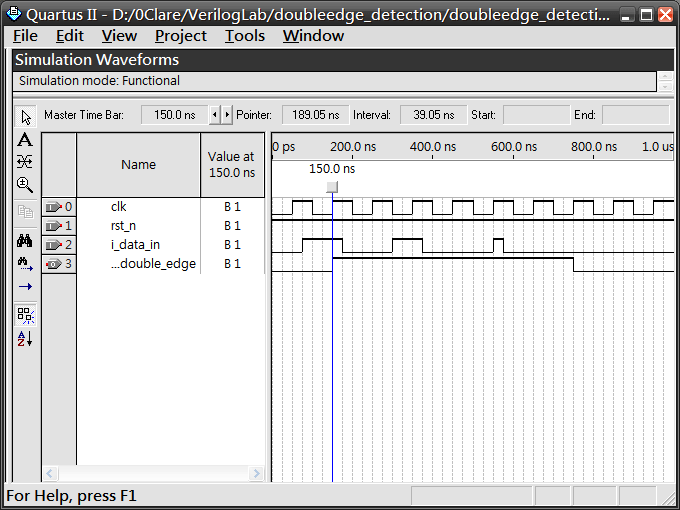
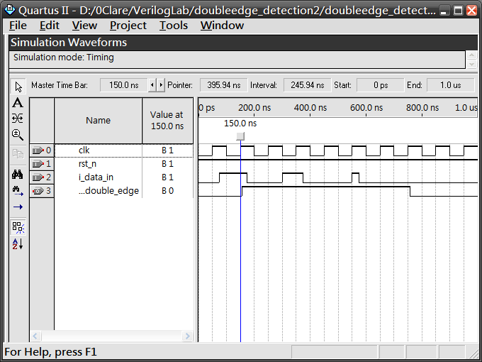
雙沿檢測電路電路(double edge detection)
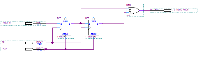
r_data_in2與r_data_in1為reg,分別hold住上一個clock與目前clock的i_data_in,所謂雙沿電路,就是i_data_in由1變0,或者由0變1,也就是r_data_in2為1且r_data_in1為0,或者r_data_in2為0且r_data_in1為1時,故用xor接r_data_in1與r_data_in2。
Method 1:
使用2個reg
doubleedge_detection.v / Verilog
- /*
- (C) OOMusou 2008 http://oomusou.cnblogs.com
-
- Filename : doubleedge_detection.v
- Compiler : Quartus II 7.2 SP3
- Description : Demo how to design double edge detection circuit
- Release : 07/06/2008 1.0
- */
-
- module doubleedge_detection (
- input clk,
- input rst_n,
- input i_data_in,
- output o_double_edge
- );
-
- reg r_data_in0;
- reg r_data_in1;
-
- assign o_double_edge = r_data_in0 ^ r_data_in1;
-
- always@(posedge clk, negedge rst_n) begin
- if (!rst_n) begin
- r_data_in0 <= 0;
- r_data_in1 <= 0;
- end
- else begin
- r_data_in0 <= r_data_in1;
- r_data_in1 <= i_data_in;
- end
- end
-
- endmodule
Method 2:
使用1個reg
doubleedge_detection2.v / Verilog
2 (C) OOMusou 2008 http://oomusou.cnblogs.com
3
4 Filename : doubleedge_detection2.v
5 Compiler : Quartus II 7.2 SP3
6 Description : Demo how to design double edge detection circuit
7 Release : 07/06/2008 1.0
8 */
9
10 module doubleedge_detection2 (
11 input clk,
12 input rst_n,
13 input i_data_in,
14 output reg o_double_edge
15 );
16
17 reg r_data_in0;
18
19 always@(posedge clk, negedge rst_n) begin
20 if (!rst_n)
21 r_data_in0 <= 0;
22 else begin
23 r_data_in0 <= i_data_in;
24
25 if ({r_data_in0, i_data_in} == 2'b10)
26 o_double_edge <= 1;
27 else if ({r_data_in0, i_data_in} == 2'b01)
28 o_double_edge <= 1;
29 else
30 o_double_edge <= 0;
31
32 // another method
33 // o_double_edge <= r_data_in0 ^ i_data_in;
34 end
35 end
36
37 endmodule
原文:http://www.cnblogs.com/oomusou/archive/2008/07/06/verilog_edge_detection_circuit.html

 浙公网安备 33010602011771号