

kernel源码(六)setup.s
1 源码


!
!    setup.s        (C) 1991 Linus Torvalds
!
! setup.s is responsible for getting the system data from the BIOS,
! and putting them into the appropriate places in system memory.
! both setup.s and system has been loaded by the bootblock.
!
! This code asks the bios for memory/disk/other parameters, and
! puts them in a "safe" place: 0x90000-0x901FF, ie where the
! boot-block used to be. It is then up to the protected mode
! system to read them from there before the area is overwritten
! for buffer-blocks.
!

! NOTE! These had better be the same as in bootsect.s!

INITSEG  = 0x9000    ! we move boot here - out of the way
SYSSEG   = 0x1000    ! system loaded at 0x10000 (65536).
SETUPSEG = 0x9020    ! this is the current segment

.globl begtext, begdata, begbss, endtext, enddata, endbss
.text
begtext:
.data
begdata:
.bss
begbss:
.text

entry start
start:

! ok, the read went well so we get current cursor position and save it for
! posterity.

    mov    ax,#INITSEG    ! this is done in bootsect already, but...
    mov    ds,ax
    mov    ah,#0x03    ! read cursor pos
    xor    bh,bh
    int    0x10        ! save it in known place, con_init fetches
    mov    [0],dx        ! it from 0x90000.

! Get memory size (extended mem, kB)

    mov    ah,#0x88
    int    0x15
    mov    [2],ax

! Get video-card data:

    mov    ah,#0x0f
    int    0x10
    mov    [4],bx        ! bh = display page
    mov    [6],ax        ! al = video mode, ah = window width

! check for EGA/VGA and some config parameters

    mov    ah,#0x12
    mov    bl,#0x10
    int    0x10
    mov    [8],ax
    mov    [10],bx
    mov    [12],cx

! Get hd0 data

    mov    ax,#0x0000
    mov    ds,ax
    lds    si,[4*0x41]
    mov    ax,#INITSEG
    mov    es,ax
    mov    di,#0x0080
    mov    cx,#0x10
    rep
    movsb

! Get hd1 data

    mov    ax,#0x0000
    mov    ds,ax
    lds    si,[4*0x46]
    mov    ax,#INITSEG
    mov    es,ax
    mov    di,#0x0090
    mov    cx,#0x10
    rep
    movsb

! Check that there IS a hd1 :-)

    mov    ax,#0x01500
    mov    dl,#0x81
    int    0x13
    jc    no_disk1
    cmp    ah,#3
    je    is_disk1
no_disk1:
    mov    ax,#INITSEG
    mov    es,ax
    mov    di,#0x0090
    mov    cx,#0x10
    mov    ax,#0x00
    rep
    stosb
is_disk1:

! now we want to move to protected mode ...

    cli            ! no interrupts allowed !

! first we move the system to it's rightful place

    mov    ax,#0x0000
    cld            ! 'direction'=0, movs moves forward
do_move:
    mov    es,ax        ! destination segment
    add    ax,#0x1000
    cmp    ax,#0x9000
    jz    end_move
    mov    ds,ax        ! source segment
    sub    di,di
    sub    si,si
    mov     cx,#0x8000
    rep
    movsw
    jmp    do_move

! then we load the segment descriptors

end_move:
    mov    ax,#SETUPSEG    ! right, forgot this at first. didn't work :-)
    mov    ds,ax
    lidt    idt_48        ! load idt with 0,0
    lgdt    gdt_48        ! load gdt with whatever appropriate

! that was painless, now we enable A20

    call    empty_8042
    mov    al,#0xD1        ! command write
    out    #0x64,al
    call    empty_8042
    mov    al,#0xDF        ! A20 on
    out    #0x60,al
    call    empty_8042

! well, that went ok, I hope. Now we have to reprogram the interrupts :-(
! we put them right after the intel-reserved hardware interrupts, at
! int 0x20-0x2F. There they won't mess up anything. Sadly IBM really
! messed this up with the original PC, and they haven't been able to
! rectify it afterwards. Thus the bios puts interrupts at 0x08-0x0f,
! which is used for the internal hardware interrupts as well. We just
! have to reprogram the 8259's, and it isn't fun.

    mov    al,#0x11        ! initialization sequence
    out    #0x20,al        ! send it to 8259A-1
    .word    0x00eb,0x00eb        ! jmp $+2, jmp $+2
    out    #0xA0,al        ! and to 8259A-2
    .word    0x00eb,0x00eb
    mov    al,#0x20        ! start of hardware int's (0x20)
    out    #0x21,al
    .word    0x00eb,0x00eb
    mov    al,#0x28        ! start of hardware int's 2 (0x28)
    out    #0xA1,al
    .word    0x00eb,0x00eb
    mov    al,#0x04        ! 8259-1 is master
    out    #0x21,al
    .word    0x00eb,0x00eb
    mov    al,#0x02        ! 8259-2 is slave
    out    #0xA1,al
    .word    0x00eb,0x00eb
    mov    al,#0x01        ! 8086 mode for both
    out    #0x21,al
    .word    0x00eb,0x00eb
    out    #0xA1,al
    .word    0x00eb,0x00eb
    mov    al,#0xFF        ! mask off all interrupts for now
    out    #0x21,al
    .word    0x00eb,0x00eb
    out    #0xA1,al

! well, that certainly wasn't fun :-(. Hopefully it works, and we don't
! need no steenking BIOS anyway (except for the initial loading :-).
! The BIOS-routine wants lots of unnecessary data, and it's less
! "interesting" anyway. This is how REAL programmers do it.
!
! Well, now's the time to actually move into protected mode. To make
! things as simple as possible, we do no register set-up or anything,
! we let the gnu-compiled 32-bit programs do that. We just jump to
! absolute address 0x00000, in 32-bit protected mode.

    mov    ax,#0x0001    ! protected mode (PE) bit
    lmsw    ax        ! This is it!
    jmpi    0,8        ! jmp offset 0 of segment 8 (cs)

! This routine checks that the keyboard command queue is empty
! No timeout is used - if this hangs there is something wrong with
! the machine, and we probably couldn't proceed anyway.
empty_8042:
    .word    0x00eb,0x00eb
    in    al,#0x64    ! 8042 status port
    test    al,#2        ! is input buffer full?
    jnz    empty_8042    ! yes - loop
    ret

gdt:
    .word    0,0,0,0        ! dummy

    .word    0x07FF        ! 8Mb - limit=2047 (2048*4096=8Mb)
    .word    0x0000        ! base address=0
    .word    0x9A00        ! code read/exec
    .word    0x00C0        ! granularity=4096, 386

    .word    0x07FF        ! 8Mb - limit=2047 (2048*4096=8Mb)
    .word    0x0000        ! base address=0
    .word    0x9200        ! data read/write
    .word    0x00C0        ! granularity=4096, 386

idt_48:
    .word    0            ! idt limit=0
    .word    0,0            ! idt base=0L

gdt_48:
    .word    0x800        ! gdt limit=2048, 256 GDT entries
    .word    512+gdt,0x9    ! gdt base = 0X9xxxx

.text
endtext:
.data
enddata:
.bss
endbss:
2 分析
设置数据段寄存器ds到0x90000位置。在bootsect.s中我们移动bootsect.s到0x90000位置,移动setup.s到0x90200位置,这里我们覆盖bootsect.s。
读取光标位置并存储在相对0x90000的[0]位置
! ok, the read went well so we get current cursor position and save it for
! posterity.

    mov    ax,#INITSEG    ! this is done in bootsect already, but...
    mov    ds,ax //设置数据段寄存器为0x90000,
    mov    ah,#0x03    ! read cursor pos
    xor    bh,bh
    int    0x10        ! 调用BIOS中断,功能号为0x03,入参bh=0表示显示页码,出口参数为:dh为行,dl为列
   mov    [0],dx        ! 保存中断返回的光标位置到0x90000处,dx为16位,ds为8位,实际占用ds[0]和ds[1]
注:BIOS中断向量表:https://blog.csdn.net/weixin_37656939/article/details/79684611
获取扩展内存大小
! Get memory size (extended mem, kB)

    mov    ah,#0x88
    int    0x15 //调用BIOS中断,功能号0x15,入参:ah=0x88表示获取扩展内存大小,出口参数:ax:扩展内存大小(单位KB)
    mov    [2],ax //把读取的扩展内存大小存入0x90002位置
获取显示卡数据
! Get video-card data:

    mov    ah,#0x0f
    int    0x10 //调用BIOS中断,功能号0x10,入参:ah=0x0f表示获取显示器模式,出口参数:bh页码,ah屏幕字符的列数,al显示模式
    mov    [4],bx        ! 把获取的页码存入0x90004位置
    mov    [6],ax        ! 把获取的屏幕宽度和显示模式放入0x90006位置
获取显示参数:
! check for EGA/VGA and some config parameters

    mov    ah,#0x12
    mov    bl,#0x10
    int    0x10 //调用BIOS中断,功能号0x10,入参:bl=0x10
    mov    [8],ax
    mov    [10],bx //安装的显示内存放入相对0x90000位置10处
    mov    [12],cx //显示卡的特性放到相对0x90000位置12处
取第一个硬盘的信息
此处没有使用bios中断获取硬盘信息,因为bios中断向量表已经被加载到0-0x3FF位置,其中该范围内的0x41处存放的是一个地址指针,指向第0块硬盘的参数表(此处的bios中断向量0x41和0x13不同,0x13存放的是一个中断调用,而0x41存放的是硬盘参数表的指针)
第一个硬盘的参数表首地址是中断向量0x41的向量值。硬盘参数表的长度是16字节
lds指令的功能是把mem指向的地址,高位存放在DS中,低位存放在reg中
rep是循环指令,循环执行其下的一条指令,直到cx=0为止。
! Get hd0 data

    mov    ax,#0x0000
    mov    ds,ax //段的基地址改为0x0000
    lds    si,[4*0x41] //取相对0x0000处0x41处开始取16字节,高8字节放入ds中,低8字节放入源变址寄存器si中
    mov    ax,#INITSEG
    mov    es,ax //附加段es基地址设置为0x9000
    mov    di,#0x0080 es段的目的变址寄存器设置为0x0080
    mov    cx,#0x10
    rep
    movsb
上面代码最后两行,循环执行movsb,movsb是串传送指令,将ds:si处的值传送到es:di中,每次传送1字节。每循环一次cx减1,直到减到0为止。这里的功能是把硬盘参数表放到es段的0x0080开始的位置,共16字节。
下面代码是获取第二个磁盘的参数表放到es段的0x0090开始的位置,共16字节。
! Get hd1 data

    mov    ax,#0x0000
    mov    ds,ax
    lds    si,[4*0x46]
    mov    ax,#INITSEG
    mov    es,ax
    mov    di,#0x0090
    mov    cx,#0x10
    rep
    movsb
判断是否存在hd1(因为Linus开发内核时,把文件系统放到第二个硬盘中,所以有这个硬盘,但是其他人可能只有一个硬盘,这里判断是否存在hd1,如果不存在,把hd1信息清空)
! Check that there IS a hd1 :-)

    mov    ax,#0x01500
    mov    dl,#0x81
    int    0x13
    jc    no_disk1
    cmp    ah,#3
    je    is_disk1
如果没有hd1,则将0x90090开始的16个字节处理掉。
no_disk1:
    mov    ax,#INITSEG
    mov    es,ax
    mov    di,#0x0090
    mov    cx,#0x10
    mov    ax,#0x00
    rep
    stosb
如果有disk1,则开始启用保护模式
is_disk1:

! now we want to move to protected mode ...

    cli            ! Clear Interupt,该指令用于禁用中断,为什么要首先关闭中断呢?因为接下来要把system模块从0x1000移动到0x0位置处,而此位置存放的是bios中断向量表,如果不关闭中断,调用中断向量表时会找不到对应中断向量,会出问题,所以,先关闭中断

! first we move the system to it's rightful place

    mov    ax,#0x0000 !ax寄存器赋值0x000
    cld            ! 标志寄存器FLAGS中的fd标志清零
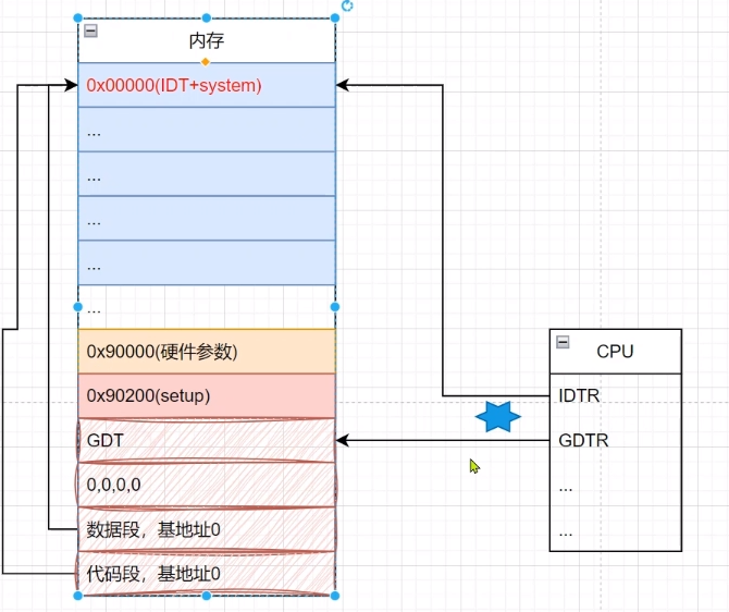
把0x10000到0x90000的内存段移动到0x0000开始的位置。通过https://www.cnblogs.com/zhenjingcool/p/15938085.html显示的示意图我们知道,0x10000到0x90000存放的是system模块,这里我们把system模块移动到0x0000开始的位置。
do_move:
    mov    es,ax        ! destination segment
    add    ax,#0x1000 //ax初始值为0x000,这里首先ax=ax+0x1000,也就是加64KB
    cmp    ax,#0x9000 //判断是否到达0x9000位置
    jz    end_move //如果到达0x9000位置,说明我们已经移动完毕
    mov    ds,ax        ! 否则ds赋值为0x1000
    sub    di,di //源变址寄存器清零
    sub    si,si //目的变址寄存器清零
    mov     cx,#0x8000 计数寄存器cx置为0x8000 (2^115=2^6K=32K),表示循环32K次,每次传送1个字,共传送32K字,也就是64K字节,即64KB
    rep //循环
    movsw //传送1个字,从ds:si到es:di
    jmp    do_move
如果移动完,则跳转到end_move
加载段描述符(全局描述符表和中断描述符表)
! then we load the segment descriptors

end_move:
    mov    ax,#SETUPSEG    ! right, forgot this at first. didn't work :-)
    mov    ds,ax //数据段的基地址移动到0x9020处
    lidt    idt_48        ! lidt指令用于加载idt。加载中断描述符表idt到idtr寄存器中,其中idt_48在下面定义。idt_48共48位,都是0,也就是说,中断描述符寄存器idtr指向内存0处
    lgdt    gdt_48        ! lgdt指令用于加载gdt。加载全局描述符表gdt到gdtr寄存器中
gdt:
    .word    0,0,0,0        ! dummy

    .word    0x07FF        ! 8Mb - limit=2047 (2048*4096=8Mb)
    .word    0x0000        ! base address=0
    .word    0x9A00        ! code read/exec
    .word    0x00C0        ! granularity=4096, 386

    .word    0x07FF        ! 8Mb - limit=2047 (2048*4096=8Mb)
    .word    0x0000        ! base address=0
    .word    0x9200        ! data read/write
    .word    0x00C0        ! granularity=4096, 386

idt_48: //这里定义了3个word,每个word16位,共48位。这里相当于定义的中断描述符表共48位,每位全为0。
    .word    0            ! idt limit=0
    .word    0,0            ! idt base=0L

gdt_48: //这里定义了3个word,共48位。
    .word    0x800        ! gdt limit=2048, 256 GDT entries
    .word    512+gdt,0x9    ! gdt base = 0X9xxxx,512是十进制,对应的十六进制为0x200。gdt在上面定义,定义了12个word,也就是初始的全局描述符表。
上述对gdt_48的描述可比照下图查看会比较明了
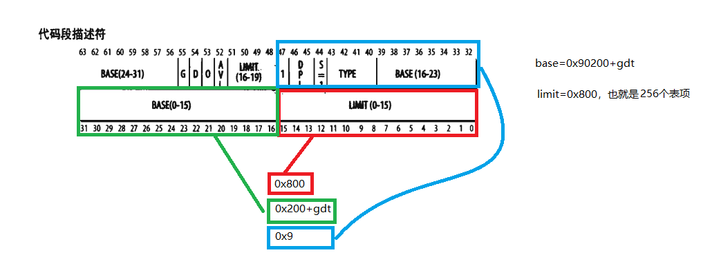
也即是说,从0x90200开始连续存放了3个gdt表项。这些表项的限长都是0x800.
达到的效果如下图所示
开启A20地址线。只有开启A20地址线,我们才能够访问1M以上的内存。(代码暂时不解释,只要知道这里功能是开启A20地址线)
! that was painless, now we enable A20

    call    empty_8042
    mov    al,#0xD1        ! command write
    out    #0x64,al
    call    empty_8042
    mov    al,#0xDF        ! A20 on
    out    #0x60,al
    call    empty_8042
重新设置8259A控制器(8259A是专门为8086/8088进行中断控制而设计的芯片),这段代码暂时不讲,下一篇再详细讲述
! well, that went ok, I hope. Now we have to reprogram the interrupts :-(
! we put them right after the intel-reserved hardware interrupts, at
! int 0x20-0x2F. There they won't mess up anything. Sadly IBM really
! messed this up with the original PC, and they haven't been able to
! rectify it afterwards. Thus the bios puts interrupts at 0x08-0x0f,
! which is used for the internal hardware interrupts as well. We just
! have to reprogram the 8259's, and it isn't fun.

    mov    al,#0x11        ! initialization sequence
    out    #0x20,al        ! send it to 8259A-1
    .word    0x00eb,0x00eb        ! jmp $+2, jmp $+2
    out    #0xA0,al        ! and to 8259A-2
    .word    0x00eb,0x00eb
    mov    al,#0x20        ! start of hardware int's (0x20)
    out    #0x21,al
    .word    0x00eb,0x00eb
    mov    al,#0x28        ! start of hardware int's 2 (0x28)
    out    #0xA1,al
    .word    0x00eb,0x00eb
    mov    al,#0x04        ! 8259-1 is master
    out    #0x21,al
    .word    0x00eb,0x00eb
    mov    al,#0x02        ! 8259-2 is slave
    out    #0xA1,al
    .word    0x00eb,0x00eb
    mov    al,#0x01        ! 8086 mode for both
    out    #0x21,al
    .word    0x00eb,0x00eb
    out    #0xA1,al
    .word    0x00eb,0x00eb
    mov    al,#0xFF        ! mask off all interrupts for now
    out    #0x21,al
    .word    0x00eb,0x00eb
    out    #0xA1,al
lmsw(load machine status word)加载机器状态字。也就是控制寄存器CR0的PE(protected enable)位设置为1,开启保护模式。后续再修改段寄存器,将修改的是段的选择符,而不是段的基地址(参考https://www.cnblogs.com/zhenjingcool/p/15929907.html)。
跳转到0x0000位置。
    mov    ax,#0x0001    ! protected mode (PE) bit
    lmsw    ax        ! This is it!
    jmpi    0,8        ! jmp offset 0 of segment 8 (cs),跳转到段选择子为8(二进制为1000),偏移地址为0的位置处
其中 jmpi 0,8 是我们要特别注意的地方,它是关键点。
jmpi指令是段间跳转指令。这条指令作用是跳转到段选择子为8(二进制是1000)的位置0处。通过https://www.cnblogs.com/zhenjingcool/p/15929907.html我们了解到,段选择子格式

低两位为00,TI位为0表示访问全局描述符表GDT,index为1表示GDT中的第1位(首位为第0位)
初始化的GDT为
gdt:
    .word    0,0,0,0        ! dummy

    .word    0x07FF        ! 8Mb - limit=2047 (2048*4096=8Mb)
    .word    0x0000        ! base address=0
    .word    0x9A00        ! code read/exec
    .word    0x00C0        ! granularity=4096, 386

    .word    0x07FF        ! 8Mb - limit=2047 (2048*4096=8Mb)
    .word    0x0000        ! base address=0
    .word    0x9200        ! data read/write
    .word    0x00C0        ! granularity=4096, 386
第0位保留不用,第1位为
    .word    0x07FF        ! 8Mb - limit=2047 (2048*4096=8Mb)
    .word    0x0000        ! base address=0
    .word    0x9A00        ! code read/exec
    .word    0x00C0        ! granularity=4096, 386
intel规定下(低位)上(高位),对照
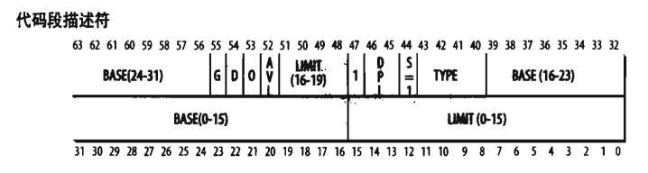
我们可知,BASE为0x00000000(32位)
也就是说执行 jmpi 0,8 将跳转到0x0000处。前面我们介绍过,0x0000位置为system模块存放的地址,也就是说接下来将执行system模块中的head.s。

 浙公网安备 33010602011771号