思科简单教程CCNA
这是CCNA的内容,从PC配置交换机(或者路由器),这里呢我们使用的软件叫pack 这是ciso开发的一款工具,能生动形象的模拟现实生活中组网技术的过程,下面我大概讲一下流程,想更多的了解我会录制一些视频,请在我的博客置顶帖去访问我的视频网站,视频链接:
CCNA手册地址:链接: http://pan.baidu.com/s/1i4ZLU1R 密码: qak4
CCNA路由器版手册: 链接: http://pan.baidu.com/s/1c2qpxC0
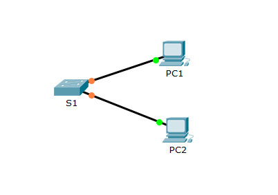
计算机和路由器是同类,交换机和集线器是同类,蓝色的线是用来调式和初始化的,实线是用来连接不同类的,虚线是用来连接同类的
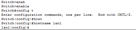
1.改名:
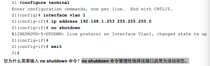
2.配ip:
ipv4的:
默认网关:
S1(config)#ip default-gateway 172.16.10.1
ipv6的:
上面那个是配置ipv4的方法,接下来是配置ipv6的方法,就换一条语句就好了
ipv6 address 手打ipv6地址
ipv6配置默认网关,记得要加link-local (好像叫本地链路。。。。我混淆了。。。)
ipv6 address FE80::1 link-local
no shutdown
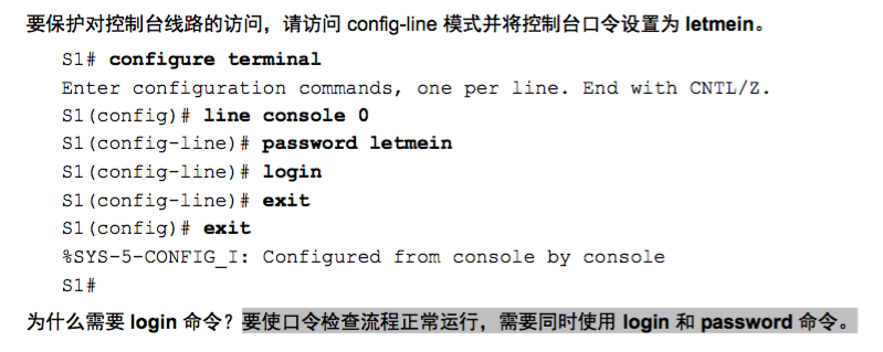
3.设置密码:
设置密码有两种方式,一种是password一种是secret,区别在于password密码是明文可以查看不安全,secret是加密过的不能查看,比较安全。不过password也可以后来进行加密
password方式:
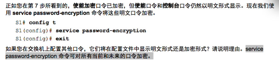
这种方法的后来进行加密:
虚拟线路是在 line vty 0
secret方式:

设置完密码之后怎么查看它是明文还是密文嘞?
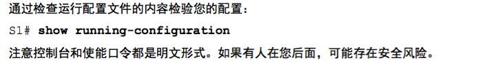
还有一点,好像这个密码设置完之后就不能删除了。。。以后知道方法了我会补充上来的。。。
补充: 想删除就在前面加上no 不管是什么都是这样的直接那个命令加个no
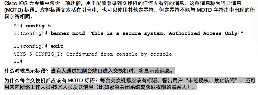
4.配置MOTD标语:
这就是一个标语而已,然而其意义还是比较重要的,据说有一个黑客黑进了一家公司,看到其MOTD标语写的是welcome....然后就义不容辞的黑了那家公司,待到那家公司发觉并将黑客告上法庭时法院判决黑客胜...
谁让你欢迎人家来的....所以呢我们要配置一下MOTD标语,让黑进来的黑客知道,这是不允许他访问的
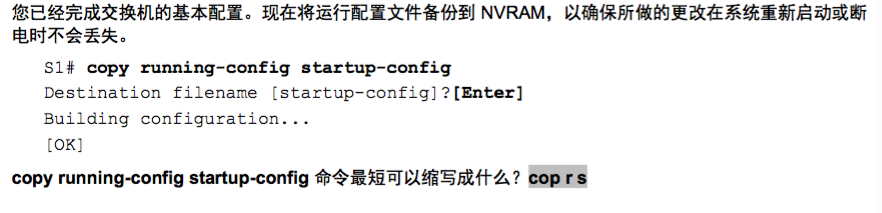
5.将配置文件保存到NVRAM:
做了那么多了,保存一下吧,万一突然断电了呢。。。
6.Default Gateway是默认网关的意思,至于怎么配好像是ip地址的最后一位改成1就好了,只是我的猜测,我不会算。。。
下面的这些呢是路由器方面的东西咯
服务器第二章
这一章我们要学习SSH,接口模式和端口安全,下面是这一章的图例:
先来SSH(SSH2也是一样,直接把SSH改成SSH2就好了)
什么是SSH?(待补充)
创建一个 SSH 用户,并重新配置 VTY 线路以仅支持 SSH 访问。
创建用户 administrator,密码是 cisco。
S1(config)# username administrator password cisco
配置 VTY 线路以检查本地用户名数据库的登录凭证,并只允许 SSH 进行远程访问。 删除现有的 vty 线路
密码。
S1(config-line)# login local
S1(config-line)# transport input ssh
S1(config-line)# no password cisco
最后检验SSH,退出 Telnet 会话并尝试使用 Telnet 重新登录。尝试会失败。
尝试使用 SSH 登录。键入 SSH 并按 Enter 键,不带任何参数,以显示命令用法说明。 提示: -l 选项表
示字母“ L”,而不是编号 1。
7.设置域名,例如设置为 shuyunquan
Switch(config)#ip domain-name shuyunquan
8.使用强密码创建你选择的用户
Switch(config)#user any-user password any-password
9.生成1024位RSA密钥
Switch(config)#crypto key generate rsa
输入这个之后,在出来的地方填写1024就好了
10.阻止两分钟内四次登录失败的任何用户,使其无法在三分钟内再次登录
Switch(config)#login block-for 180 attempts 4 within 120
11.配置vty线路进行SSH访问并要求本地用户配置文件
Switch(config)#line vty 0
Switch(config-line)#transport input ssh
Switch(config-line)#login local
SSH改成版本2
(config)#ip ssh version 2
12.禁用所有未使用的端口
//这是网卡端口
S1(config)#interface range fa0/3-24   //3~24我不用
S1(config-if-range)#shutdown    //关闭
//这是高速端口
S1(config-if-range)#interface range gi0/1-2
S1(config-if-range)#shutdown
13. 将接口模式设置为接入模式
S1(config)#interface range fa0/1 - 2
S1(config-if-range)#switchport mode access
14.启用端口安全,使每个端口仅允许两台主机
//这是启用端口安全
S1(config)#interface range fa0/1 - 2
S1(config-if-range)#switchport port-security
//这是每个端口允许两台主机
S1(config)#interface range fa0/1-2
S1(config-if-range)#switchport port-security maximum 2
15.在运行配置中记录 MAC 地址
S1(config)#interface range fa0/1-2
S1(config-if-range)#switchport port-security mac-address sticky
16.确保在发生端口违规时是否禁用端口?
S1(config)#interface range fa0/1-2
//违规时不禁用
S1(config-if-range)#switchport port-security violation restrict
//违规时禁用
S1(config-if-range)#switchport port-security violation shutdown
服务器第三章
这一章主要是学习 创建vlan并分配端口 本征vlan和trunk端口
17.创建vlan10命名为sales,分配f0/7-12端口(我改了两次了,玩死我?)
S3(config)#vlan 10
S3(config-vlan)#name sales
S3(config-vlan)#exit
S3(config)#interface range f0/7-12
S3(config-if-range)#switchport access vlan 10
18. 将本征 VLAN 99 分配到 TRUNK 端口并禁用 DTP。 限制 TRUNK 只允许 VLAN 10、20、30、88 和 99。使用 VLAN 99 作为 TRUNK 端口的本征 VLAN。(本征vlan和trunk端口不懂什么意思,下面虽是答案,待考究)
interface g0/2          //不懂为什么要进入这个端口?待考究
switchport trunk native vlan 99
switchport trunk allowed vlan 10,20,30,88,99
switchport mode trunk
switchport nonegotiate
服务器第四章,第五章没什么讲的
服务器第六章


· 根据地址分配表在 R1 上配置 VLAN 间路由。
config t
interface GigabitEthernet0/0
no shutdown

interface GigabitEthernet0/0.10
description Sales VLAN
encapsulation dot1Q 10
ip address 172.31.10.1 255.255.255.0

interface GigabitEthernet0/0.20
description Production VLAN
encapsulation dot1Q 20
ip address 172.31.20.1 255.255.255.0

interface GigabitEthernet0/0.30
description Marketing VLAN
encapsulation dot1Q 30
ip address 172.31.30.1 255.255.255.0

interface GigabitEthernet0/0.88
description Management VLAN
encapsulation dot1Q 88
ip address 172.31.88.1 255.255.255.0

interface GigabitEthernet0/0.99
description Native VLAN
encapsulation dot1Q 99 native
ip address 172.31.99.1 255.255.255.0

ip route 0.0.0.0 0.0.0.0 Serial0/0/0
· 在 S1 上配置中继。
en
config t
int g0/1
switchport mode trunk
switchport trunk native vlan 99
· 在 HQ 上配置四个分别通往 VLAN 10、20、30 和 88 的直连静态路由。
· 在 HQ 上配置到达外部主机的直连静态路由。
- 配置通过 Serial 0/1/0 接口的主路径。
- 配置通过 Serial 0/1/1 接口且 AD 为 10 的备份路由。
en
conf t
ip route 172.31.10.0 255.255.255.0 Serial0/0/0
ip route 172.31.20.0 255.255.255.0 Serial0/0/0
ip route 172.31.30.0 255.255.255.0 Serial0/0/0
ip route 172.31.88.0 255.255.255.0 Serial0/0/0
ip route 209.165.200.0 255.255.255.224 Serial0/1/0
ip route 209.165.200.0 255.255.255.224 Serial0/1/1 10
· 在 ISP 上为整个 172.31.0.0/17 地址空间配置直连主总结路由和直连备份总结路由。
- 配置通过 Serial 0/1/1 接口的主路径。
- 配置通过 Serial 0/1/0 接口且 AD 为 25 的备份路由。
en
conf t
ip route 172.31.0.0 255.255.128.0 Serial0/1/1
ip route 172.31.0.0 255.255.128.0 Serial0/1/0 25
服务器第七章
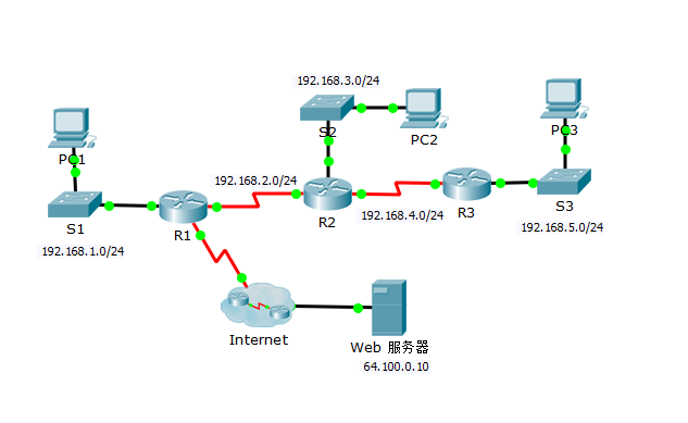
这一章我们学习 配置RIPv2
这一章的图例:
ok,开始咯
第 1 步: 在 R1 上配置 RIPv2。
a. 使用适当的命令在 R1 上创建一条默认路由,使所有 Internet 流量通过 S0/0/1 退出网络。
R1(config)# ip route 0.0.0.0 0.0.0.0 s0/0/1
b. 进入 RIP 协议配置模式。
R1(config)# router rip
c. 使用 RIP 协议的第 2 版并禁用网络总结。
R1(config-router)# version 2
R1(config-router)# no auto-summary
d. 为连接 R1 的网络配置 RIP。
R1(config-router)# network 192.168.1.0
R1(config-router)# network 192.168.2.0
e. 配置不包含路由器的 LAN 端口,以使其不发送任何路由信息。
R1(config-router)# passive-interface gig 0/0
f. 通过其他 RIP 路由器,通告第 1a 步中配置的默认路由。
R1(config-router)# default-information originate
g. 保存配置。
第 2 步: 在 R2 上配置 RIPv2。
a. 进入 RIP 协议配置模式。
R2(config)# router rip
b. 使用 RIP 协议的第 2 版并禁用网络总结。
R2(config-router)# version 2
R2(config-router)# no auto-summary
c. 为直接连接 R2 的网络配置 RIP。
R2(config-router)# network 192.168.2.0
R2(config-router)# network 192.168.3.0
R2(config-router)# network 192.168.4.0
d. 配置不包含路由器的接口,以使其不发送路由信息。
R2(config-router)# passive-interface gig 0/0
e. 保存配置。
第 3 步: 在 R3 上配置 RIPv2
在 R3 上重复第 2 步。
R3(config)# router rip
R3(config-router)# version 2
R3(config-router)# no auto-summary
R3(config-router)# network 192.168.4.0
R3(config-router)# network 192.168.5.0
R3(config-router)# passive-inter
我先来贴个图

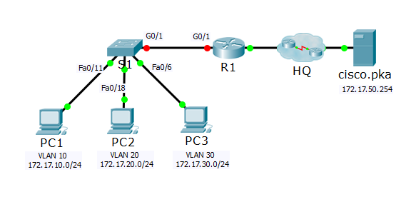
好的,看着这张图你们自己配置一下ip,我们来做
1.在 S1 上根据 VLAN 和端口分配表创建、命名并分配 VLAN。端口应处于接入模式。
先来创建,命名vlan 都是差不多的,所以我只举例一个
S1(config)#vlan 10
S1(config-vlan)#name Faculty/Staff
然后我们来分配vlan,设置端口处于接入模式
S1(config)#interface range fastEthernet 0/11 - 17
S1(config-if-range)#switchport mode access
S1(config-if-range)#switchport access vlan 10
R1配置ip和配置vlan间路由
R1(config)#interface g0/1.10
R1(config-subif)#encapsulation dot1Q 10
R1(config-subif)#ip address 172.17.10.1 255.255.255.0
R1(config-subif)#interface g0/1.20
R1(config-subif)#encapsulation dot1Q 20
R1(config-subif)#ip address 172.17.20.1 255.255.255.0
R1(config-subif)#interface g0/1.30
R1(config-subif)#encapsulation dot1Q 30
R1(config-subif)#ip address 172.17.30.1 255.255.255.0
R1(config-subif)#interface g0/1.880
R1(config-subif)#interface g0/1.88
R1(config-subif)#encapsulation dot1Q 88 native
R1(config-subif)#ip address 172.17.88.1 255.255.255.0
R1(config-subif)#interface g0/1.99
R1(config-subif)#encapsulation dot1Q 99
R1(config-subif)#ip address 172.17.99.1 255.255.255.0

 浙公网安备 33010602011771号