
vlan的创建与划分
一、实验目的:
1.了解vlan的工作原理;
2.学习基于端口划分vlan的方法;
3.了解跨交换机的相同vlan之间的通信;
4.进一步学习交换机端口的配置命令。
二、实验原理:
VLAN(Virtual Local Area Network)即虚拟局域网,是一种通过将局域网内的设备逻辑地而不是物理地划分成一个个网段从而实现虚拟工作组的新兴技术。
VLAN技术允许网络管理者将一个物理的LAN逻辑地划分成不同的广播域(或称虚拟LAN,即VLAN),每一个VLAN都包含一组有着相同需求的计算机工作站,与物理上形成的LAN有着相同的属性。但由于它是逻辑地而不是物理地划分,所以同一个VLAN内的各个工作站无须被放置在同一个物理空间里,即这些工作站不一定属于同一个物理LAN网段。一个VLAN内部的广播和单播流量都不会转发到其他VLAN中,从而有助于控制流量、减少设备投资、简化网络管理、提高网络的安全性。
VLAN是为解决以太网的广播问题和安全性而提出的一种协议,它在以太网帧的基础上增加了VLAN头,用VLAN ID把用户划分为更小的工作组,限制不同工作组间的用户二层互访,每个工作组就是一个虚拟局域网。虚拟局域网的好处是可以限制广播范围,并能够形成虚拟工作组,动态管理网络。
三、实验设备:
pc机、交换机
四、实验拓扑图(拓扑图上要标明所用交换机型号、所用交换机的端口号以及各主机配置的IP地址):
1.同一个交换机上的vlan划分:将四台计算机连接到一台交换机上,将其中两台计算机划分到一个vlan中,另两台计算机划分到另一个vlan中,验证同vlan中的计算机和不同vlan中的计算机之间的通信。注:vlan的名字不能用vlan1。
2.进行跨交换机的相同vlan之间的计算机和不同vlan之间的计算机的通信实验。
五、实验过程(配置过程):
实验一:一个交换机上实现虚拟局域网拓扑图
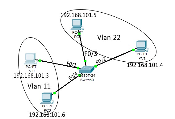
各主机配置的IP地址
pc0: 192.168.101.3,连接端口F0/1
pc1: 192.168.101.4,连接端口F0/2
pc2: 192.168.101.5,连接端口F0/3
pc3: 192.168.101.6,连接端口F0/4
步骤1:划分子网,在交换机switch0上创建虚拟局域网VLAN11和VLAN22
Switch>enable
Switch#config
Configuring from terminal, memory, or network [terminal]?
Enter configuration commands, one per line. End with CNTL/Z.
Switch(config)#hostname S1
S1(config)#vlan 22
S1(config-vlan)#name T22
S1(config-vlan)#exit
S1(config)#vlan 11
S1(config-vlan)#name T11
S1(config-vlan)#exit
S1(config)#
验证虚拟局域网VLAN11和VLAN22已创建成功:
S1#show vlan
VLAN Name Status Ports
---- -------------------------------- --------- -------------------------------
1 default active Fa0/1, Fa0/2, Fa0/3, Fa0/4
Fa0/5, Fa0/6, Fa0/7, Fa0/8
Fa0/9, Fa0/10, Fa0/11, Fa0/12
Fa0/13, Fa0/14, Fa0/15, Fa0/16
Fa0/17, Fa0/18, Fa0/19, Fa0/20
Fa0/21, Fa0/22, Fa0/23, Fa0/24
Gig1/1, Gig1/2
11 T11 active
22 T22 active
1002 fddi-default act/unsup
1003 token-ring-default act/unsup
1004 fddinet-default act/unsup
1005 trnet-default act/unsup
VLAN Type SAID MTU Parent RingNo BridgeNo Stp BrdgMode Trans1 Trans2
---- ----- ---------- ----- ------ ------ -------- ---- -------- ------ ------
1 enet 100001 1500 - - - - - 0 0
11 enet 100011 1500 - - - - - 0 0
22 enet 100022 1500 - - - - - 0 0
1002 fddi 101002 1500 - - - - - 0 0
1003 tr 101003 1500 - - - - - 0 0
1004 fdnet 101004 1500 - - - ieee - 0 0
1005 trnet 101005 1500 - - - ibm - 0 0
Remote SPAN VLANs
------------------------------------------------------------------------------
Primary Secondary Type Ports
------- --------- ----------------- ------------------------------------------
步骤2:将pc0和pc3划分到虚拟网段vlan11,pc1和pc2划分到虚拟网段vlan22.
Switch>enable
Switch#config
Configuring from terminal, memory, or network [terminal]?
Enter configuration commands, one per line. End with CNTL/Z.
Switch(config)#hostname S1
S1(config)#vlan 22
S1(config-vlan)#name T22
S1(config-vlan)#exit
S1(config)#vlan 11
S1(config-vlan)#name T11
S1(config-vlan)#exit
S1(config)#
验证为VLAN11和VLAN22分配端口成功
S1#show vlan
VLAN Name Status Ports
---- -------------------------------- --------- -------------------------------
1 default active Fa0/5, Fa0/6, Fa0/7, Fa0/8
Fa0/9, Fa0/10, Fa0/11, Fa0/12
Fa0/13, Fa0/14, Fa0/15, Fa0/16
Fa0/17, Fa0/18, Fa0/19, Fa0/20
Fa0/21, Fa0/22, Fa0/23, Fa0/24
Gig1/1, Gig1/2
11 T11 active Fa0/1, Fa0/4
22 T22 active Fa0/2, Fa0/3
1002 fddi-default act/unsup
1003 token-ring-default act/unsup
1004 fddinet-default act/unsup
1005 trnet-default act/unsup
VLAN Type SAID MTU Parent RingNo BridgeNo Stp BrdgMode Trans1 Trans2
---- ----- ---------- ----- ------ ------ -------- ---- -------- ------ ------
1 enet 100001 1500 - - - - - 0 0
11 enet 100011 1500 - - - - - 0 0
22 enet 100022 1500 - - - - - 0 0
1002 fddi 101002 1500 - - - - - 0 0
1003 tr 101003 1500 - - - - - 0 0
1004 fdnet 101004 1500 - - - ieee - 0 0
1005 trnet 101005 1500 - - - ibm - 0 0
Remote SPAN VLANs
------------------------------------------------------------------------------
Primary Secondary Type Ports
------- --------- ----------------- ------------------------------------------
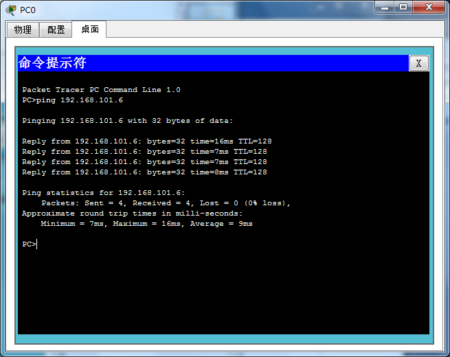
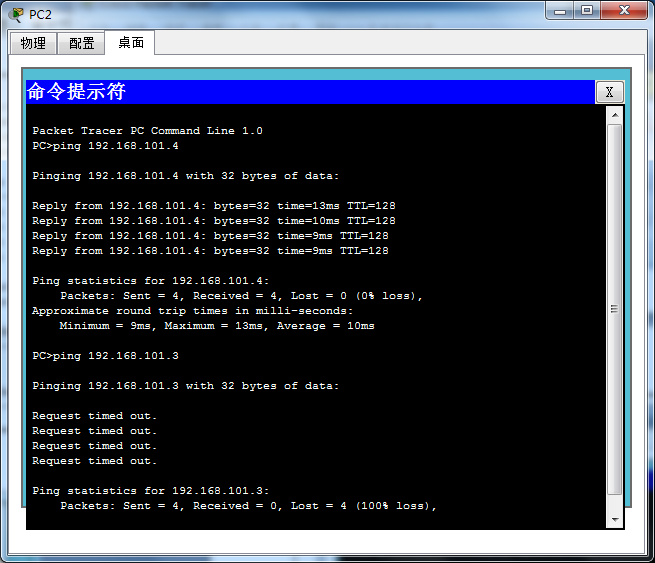
步骤3:检查4台pc之间的通信情况
pc0 ping pc3
pc2 分别ping pc1和pc0
实验二:跨交换机实现虚拟局域网

交换机Switch3端口0/1和Switch4端口0/1相连
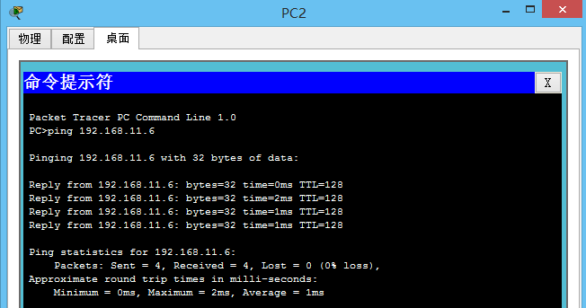
pc0: 192.168.11.3,连接交换机Switch3端口0/2
pc3: 192.168.11.6,连接交换机Switch3端口0/3
pc1: 192.168.11.4,连接交换机Switch4端口0/2
pc2: 192.168.11.5,连接交换机Switch4端口0/3
步骤1:将交换机Switch3重命名为s1并在S1上创建虚拟局域网VLAN11和VLAN22并为之分配端口。
Switch>enable
Switch#config
Configuring from terminal, memory, or network [terminal]?
Enter configuration commands, one per line. End with CNTL/Z.
Switch(config)#hostname S1
S1(config)#vlan 11
S1(config-vlan)#name T11
S1(config-vlan)#exit
S1(config)#interface fastethernet 0/2
S1(config-if)#switchport access vlan 11
S1(config-if)#exit
S1(config)#vlan 22
S1(config-vlan)#name T22
S1(config-vlan)#exit
S1(config)#interface fastethernet 0/3
S1(config-if)#switchport access vlan 22
S1(config-if)#exit
S1(config)#exit
S1#
%SYS-5-CONFIG_I: Configured from console by console
S1#show vlan
VLAN Name Status Ports
---- -------------------------------- --------- -------------------------------
1 default active Fa0/1, Fa0/4, Fa0/5, Fa0/6
Fa0/7, Fa0/8, Fa0/9, Fa0/10
Fa0/11, Fa0/12, Fa0/13, Fa0/14
Fa0/15, Fa0/16, Fa0/17, Fa0/18
Fa0/19, Fa0/20, Fa0/21, Fa0/22
Fa0/23, Fa0/24, Gig1/1, Gig1/2
11 T11 active Fa0/2
22 T22 active Fa0/3
1002 fddi-default act/unsup
1003 token-ring-default act/unsup
1004 fddinet-default act/unsup
1005 trnet-default act/unsup
VLAN Type SAID MTU Parent RingNo BridgeNo Stp BrdgMode Trans1 Trans2
---- ----- ---------- ----- ------ ------ -------- ---- -------- ------ ------
1 enet 100001 1500 - - - - - 0 0
11 enet 100011 1500 - - - - - 0 0
22 enet 100022 1500 - - - - - 0 0
1002 fddi 101002 1500 - - - - - 0 0
步骤2:将S1的F0/1端口设置为trunk模式
S1#config
Configuring from terminal, memory, or network [terminal]?
Enter configuration commands, one per line. End with CNTL/Z.
S1(config)#interface fastethernet 0/1
S1(config-if)#switchport mode trunk
%LINEPROTO-5-UPDOWN: Line protocol on Interface FastEthernet0/1, changed state to down
%LINEPROTO-5-UPDOWN: Line protocol on Interface FastEthernet0/1, changed state to up
S1(config-if)#exit
S1(config)#exit
S1#show interfaces fastEthernet 0/1 switchport
Name: Fa0/1
Switchport: Enabled
Administrative Mode: trunk
Operational Mode: trunk
Administrative Trunking Encapsulation: dot1q
Operational Trunking Encapsulation: dot1q
Negotiation of Trunking: On
Access Mode VLAN: 1 (default)
Trunking Native Mode VLAN: 1 (default)
Voice VLAN: none
Administrative private-vlan host-association: none
Administrative private-vlan mapping: none
Administrative private-vlan trunk native VLAN: none
Administrative private-vlan trunk encapsulation: dot1q
Administrative private-vlan trunk normal VLANs: none
Administrative private-vlan trunk private VLANs: none
Operational private-vlan: none
Trunking VLANs Enabled: ALL
Pruning VLANs Enabled: 2-1001
Capture Mode Disabled
Capture VLANs Allowed: ALL
Protected: false
Appliance trust: none
步骤3:将交换机Switch4重命名为s2并在S2上创建虚拟局域网VLAN11和VLAN22并为之分配端口
Switch>enable
Switch#config
Configuring from terminal, memory, or network [terminal]?
Enter configuration commands, one per line. End with CNTL/Z.
Switch(config)#hostname S2
S2(config)#vlan 11
S2(config-vlan)#name T11
S2(config-vlan)#exit
S2(config)#interface fastEthernet 0/2
S2(config-if)#switchport access vlan 11
S2(config-if)#exit
S2(config)#vlan 22
S2(config-vlan)#name T22
S2(config-vlan)#exit
S2(config)#interface fastEthernet 0/3
S2(config-if)#switchport access vlan 22
S2(config-if)#exit
S2(config)#exit
S2#
%SYS-5-CONFIG_I: Configured from console by console
S2#show vlan
VLAN Name Status Ports
---- -------------------------------- --------- -------------------------------
1 default active Fa0/4, Fa0/5, Fa0/6, Fa0/7
Fa0/8, Fa0/9, Fa0/10, Fa0/11
Fa0/12, Fa0/13, Fa0/14, Fa0/15
Fa0/16, Fa0/17, Fa0/18, Fa0/19
Fa0/20, Fa0/21, Fa0/22, Fa0/23
Fa0/24, Gig1/1, Gig1/2
11 T11 active Fa0/2
22 T22 active Fa0/3
1002 fddi-default act/unsup
1003 token-ring-default act/unsup
1004 fddinet-default act/unsup
1005 trnet-default act/unsup
VLAN Type SAID MTU Parent RingNo BridgeNo Stp BrdgMode Trans1 Trans2
---- ----- ---------- ----- ------ ------ -------- ---- -------- ------ ------
1 enet 100001 1500 - - - - - 0 0
11 enet 100011 1500 - - - - - 0 0
22 enet 100022 1500 - - - - - 0 0
1002 fddi 101002 1500 - - - - - 0 0
1003 tr 101003 1500 - - - - - 0 0
1004 fdnet 101004 1500 - - - ieee - 0 0
1005 trnet 101005 1500 - - - ibm - 0 0
Remote SPAN VLANs
------------------------------------------------------------------------------
Primary Secondary Type Ports
------- --------- ----------------- ------------------------------------------
步骤4:将S2的F0/1端口设置为trunk模式
S2#config
Configuring from terminal, memory, or network [terminal]?
Enter configuration commands, one per line. End with CNTL/Z.
S2(config)#interface fastEthernet 0/1
S2(config-if)#switchport mode trunk
S2(config-if)#exit
S2(config)#exit
S2#show interfaces fastEthernet 0/1 switchport
Name: Fa0/1
Switchport: Enabled
Administrative Mode: trunk
Operational Mode: trunk
Administrative Trunking Encapsulation: dot1q
Operational Trunking Encapsulation: dot1q
Negotiation of Trunking: On
Access Mode VLAN: 1 (default)
Trunking Native Mode VLAN: 1 (default)
Voice VLAN: none
Administrative private-vlan host-association: none
Administrative private-vlan mapping: none
Administrative private-vlan trunk native VLAN: none
Administrative private-vlan trunk encapsulation: dot1q
Administrative private-vlan trunk normal VLANs: none
Administrative private-vlan trunk private VLANs: none
Operational private-vlan: none
Trunking VLANs Enabled: ALL
Pruning VLANs Enabled: 2-1001
Capture Mode Disabled
Capture VLANs Allowed: ALL
Protected: false
Appliance trust: none
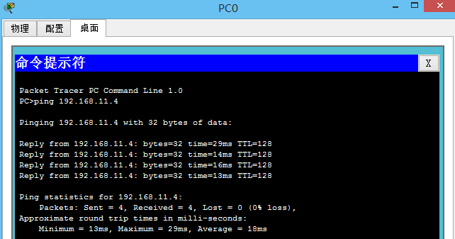
步骤5:验证局域网之间的通信情况
pc0 ping pc1
pc0 ping pc3
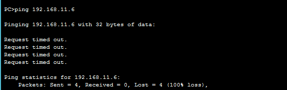
pc2 ping pc3
pc1 ping pc2

六、实验总结:
通过本次实验,可以发现,不管是只有一个交换机,还是跨交换机,只有在相同的局域网上pc机之间才能通信,不在同一个局域网的pc之间不能通信。
 posted on

 浙公网安备 33010602011771号