

完整教程:基于RIP协议的全网互通网络配置
实验拓扑
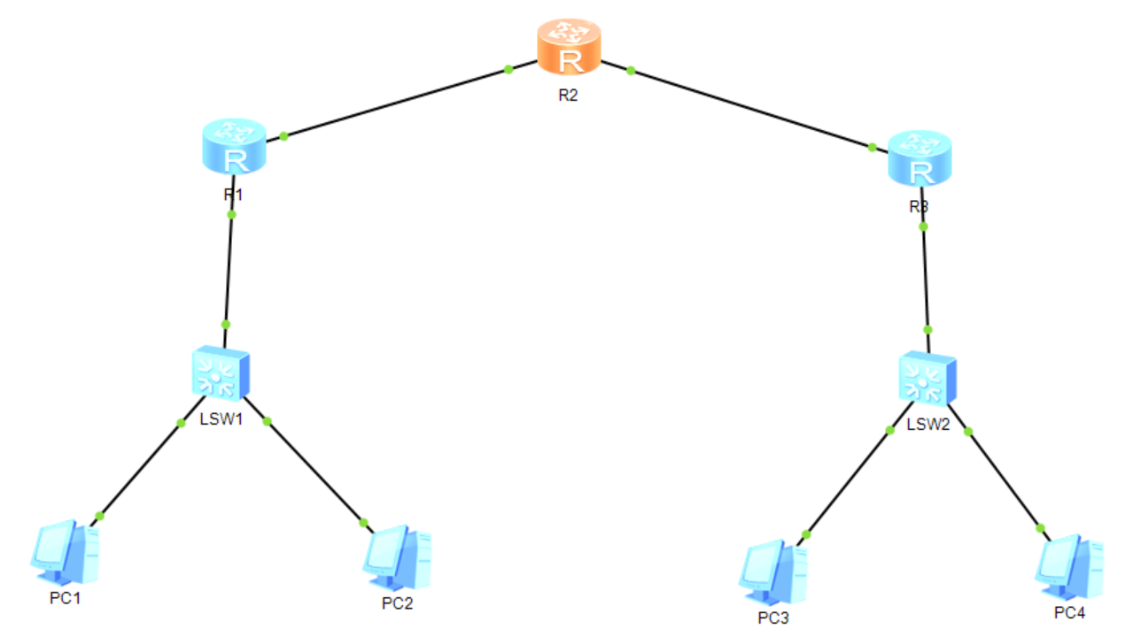
需求
1、路由器上分别设置环回
2、连接路由器的线路网段为12.1.1.0/24、23.1.1.0/24
3、R1和R3连接的网络地址分别为192.168.1.0/24、192.168.2.0/24
4、整个网络使用RIP达到全网可达
需求分析
1.三个路由器的环回地址分别为1.1.1.1/32,2.2.2.2/32,3.3.3.3/32
2.注意主机号全0不能作为主机的IP地址
3.运用到的动态路由协议:RIP动态路由协议
所有设备的配置
2.1 路由器R1配置
system-view
sysname R1# 设置环回接口
interface LoopBack0
ip address 1.1.1.1 255.255.255.255# 配置连接交换机的接口
interface Ethernet0/0/0
ip address 192.168.1.1 255.255.255.0# 配置连接R2的接口
interface Ethernet0/0/1
ip address 12.1.1.1 255.255.255.0# 配置RIP协议
rip 1
version 2
network 1.0.0.0
network 12.0.0.0
network 192.168.1.0
2.2 路由器R2配置
system-view
sysname R2# 配置环回接口
interface LoopBack0
ip address 2.2.2.2 255.255.255.255# 调整连接R1的接口
interface Ethernet0/0/0
ip address 12.1.1.2 255.255.255.0# 配置连接R3的接口
interface Ethernet0/0/1
ip address 23.1.1.2 255.255.255.0# 部署RIP协议
rip 1
version 2
network 2.0.0.0
network 12.0.0.0
network 23.0.0.0
2.3 路由器R3调整
system-view
sysname R3# 配置环回接口
interface LoopBack0
ip address 3.3.3.3 255.255.255.255# 配置连接R2的接口
interface Ethernet0/0/0
ip address 23.1.1.3 255.255.255.0# 调整连接交换机的接口
interface Ethernet0/0/1
ip address 192.168.2.1 255.255.255.0# 配置RIP协议
rip 1
version 2
network 3.0.0.0
network 23.0.0.0
network 192.168.2.0
2.4 PC地址配置
PC1: IP 192.168.1.10/24,网关 192.168.1.1
PC2: IP 192.168.1.20/24,网关 192.168.1.1
PC3: IP 192.168.2.10/24,网关 192.168.2.1
PC4: IP 192.168.2.20/24,网关 192.168.2.1
结果验证
3.1 查看RIP路由表
在R1上执行“display rip 1 route”查看学习到的RIP路由
3.2 测试路由器间连通性
在R1上ping测试:
<R1> ping 3.3.3.3
PING 3.3.3.3: 56 data bytes, press CTRL_C to break
Reply from 3.3.3.3: bytes=56 Sequence=1 ttl=254 time=30 ms
Reply from 3.3.3.3: bytes=56 Sequence=2 ttl=254 time=20 ms
Reply from 3.3.3.3: bytes=56 Sequence=3 ttl=254 time=30 ms
3.3 测试跨网段PC连通性
同理,在PC1上ping PC3
3.4 验证本地网络连通性
同理,在PC1上ping同网段的PC2
总结
1.network命令发布直连网段(主类地址)

 浙公网安备 33010602011771号