

使用OGR创建弧形图形
很多时候我们需要在矢量文件中记录一些弧形图形,由于目前OGR中没有支持通过圆心半径等方式来保存矢量图形,所以对于这些矢量图形必须要计算出弧线上的点坐标来进行存储,如果自己按照圆弧的算法来创建这些点确实有些麻烦,OGR中提供了一个叫approximateArcAngles的函数来对圆弧点坐标进行计算,使用起来非常方便,下面是该函数的一个简单说明。函数原型为:
创建一段椭圆弧段。指定一个原点坐标、椭圆的长半轴长度、短半轴长度、旋转角度、起始角度和结束角度来生成一段弧段。参数dfMaxAngleStepSizeDegrees用来指定最大步长,可以使用配置选项OGR_ARC_STEPSIZE来进行设置默认值。生成弧段如图1所示,左侧和下侧两条白色线段分别为X轴和Y轴,交点为坐标原点,绿色椭圆的圆心坐标为(dfCenterX,dfCenterY,dfZ),长半轴和短半轴长度分别如图中两条蓝色线段表示,起始角度和结束角度方向射线如图中紫色线段所示,图中红色的弧段即为生成的弧段。
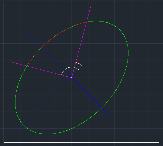
图1 函数参数说明示意图
OGRGeometry * OGRGeometryFactory::approximateArcAngles(
double dfCenterX,
double dfCenterY,
double dfZ,
double dfPrimaryRadius,
double dfSecondaryRadius,
double dfRotation,
double dfStartAngle,
double dfEndAngle,
double dfMaxAngleStepSizeDegrees )
参数说明:
dfCenterX | 椭圆原点X坐标 |
dfCenterY | 椭圆原点Y坐标 |
dfZ | 椭圆原点Z坐标 |
dfPrimaryRadius | 椭圆长半轴长度 |
dfSecondaryRadius | 椭圆短半轴长度 |
dfRotation | 椭圆顺时针旋转角度 |
dfStartAngle | 弧段起始点角度(与X轴顺时针夹角) |
dfEndAngle | 弧段结束点角度(与X轴顺时针夹角) |
dfMaxAngleStepSizeDegrees | 沿着弧段最长步长对应的角度,设置为0按默认值计算 |
void WriteVectorFile1()
{
	// 为了支持中文SHP路径,请添加下面这句代码
	CPLSetConfigOption("GDAL_FILENAME_IS_UTF8", "NO");
#ifdef CREATSHP
	// 为了使属性表字段支持中文,请添加下面这句,创建SHP
	CPLSetConfigOption("SHAPE_ENCODING", "" );
	const char* pszVectorFile = "E:\\TestArc.shp";
	const char *pszDriverName = "ESRI Shapefile";
#else
	// 创建DXF
	CPLSetConfigOption("GDAL_DATA", "C:\\warmerda\\GDAL110\\data");
	const char* pszVectorFile = "E:\\TestArc.dxf";
	const char *pszDriverName = "DXF";
#endif

	// 注册所有的驱动
	OGRRegisterAll();

	//创建数据
	OGRSFDriver *poDriver = OGRSFDriverRegistrar::GetRegistrar()->GetDriverByName(pszDriverName );
	if( poDriver == NULL )
	{
		printf( "%s 驱动不可用!\n", pszDriverName );
		return;
	}

	// 创建数据源
	OGRDataSource *poDS = poDriver->CreateDataSource(pszVectorFile, NULL );
	if( poDS == NULL )
	{
		printf( "创建矢量文件【%s】失败!\n", pszVectorFile );
		return;
	}

	// 创建图层,创建一个线图层,这里没有指定空间参考,如果需要的话,需要在这里进行指定
	OGRLayer *poLayer = poDS->CreateLayer( "TestPolygon", NULL, wkbLineString, NULL );
	if( poLayer == NULL )
	{
		printf( "图层创建失败!\n" );
		OGRDataSource::DestroyDataSource( poDS );
		return;
	}

	// 由于DXF不支持属性表,所以下面几句OGR会提示错误信息
	// 下面创建属性表
	// 先创建一个叫FieldID的整型属性
	OGRFieldDefn oFieldID("FieldID", OFTInteger);
	poLayer->CreateField(&oFieldID);

	// 再创建一个叫FeatureName的字符型属性,字符长度为
	OGRFieldDefn oFieldName("FieldName", OFTString);
	oFieldName.SetWidth(100);
	poLayer->CreateField(&oFieldName);

	OGRFeatureDefn *poDefn = poLayer->GetLayerDefn();

	// 创建两个坐标轴X和Y
	OGRFeature *poFeatureXAxis  = OGRFeature::CreateFeature(poDefn);
	poFeatureXAxis->SetField(0, 0);
	poFeatureXAxis->SetField(1, "X轴");
	OGRLineString *pGeoXAxis = (OGRLineString*)OGRGeometryFactory::createGeometry(wkbLineString) ;
	pGeoXAxis->setPoint(0, -100, 0);
	pGeoXAxis->setPoint(1,  100, 0);
	poFeatureXAxis->SetGeometry(pGeoXAxis);
	poLayer->CreateFeature( poFeatureXAxis );
	OGRFeature::DestroyFeature( poFeatureXAxis );

	// 创建Y轴
	OGRFeature *poFeatureYAxis = OGRFeature::CreateFeature(poDefn);
	poFeatureYAxis->SetField(0, 1);
	poFeatureYAxis->SetField(1, "Y轴");
	OGRLineString *pGeoYAxis = (OGRLineString*) OGRGeometryFactory::createGeometry(wkbLineString) ;
	pGeoYAxis->setPoint(0, 0, -100);
	pGeoYAxis->setPoint(1, 0, 100);
	poFeatureYAxis->SetGeometry(pGeoYAxis);
	poLayer->CreateFeature( poFeatureYAxis );
	OGRFeature::DestroyFeature( poFeatureYAxis );

	// 创建圆形要素
	OGRFeature *poFeatureCircle = OGRFeature::CreateFeature(poDefn);
	poFeatureCircle->SetField(0, 2);
	poFeatureCircle->SetField(1, "圆形");

	OGRGeometry * pCircleLine = OGRGeometryFactory::approximateArcAngles(50.0,-10.0, 0.0, 10.0, 10.0, 0.0, 0.0, 360.0, 1.0 );
	poFeatureCircle->SetGeometry(pCircleLine);

	poLayer->CreateFeature( poFeatureCircle );
	OGRFeature::DestroyFeature( poFeatureCircle );

	// 创建圆形要素
	OGRFeature *poFeatureEclipse = OGRFeature::CreateFeature(poDefn);
	poFeatureEclipse->SetField(0, 3);
	poFeatureEclipse->SetField(1, "椭圆");

	OGRGeometry * pEclipseLine = OGRGeometryFactory::approximateArcAngles(50.0, 50.0, 0.0, 10.0, 20.0, 45.0, 0.0, 360.0, 1.0 );
	poFeatureEclipse->SetGeometry(pEclipseLine);

	poLayer->CreateFeature( poFeatureEclipse );
	OGRFeature::DestroyFeature( poFeatureEclipse );

	// 创建半圆形要素
	OGRFeature *poFeatureArc = OGRFeature::CreateFeature(poDefn);
	poFeatureArc->SetField(0, 4);
	poFeatureArc->SetField(1, "半圆形");

	OGRGeometry * pArcLine = OGRGeometryFactory::approximateArcAngles(-50.0,50.0, 0.0, 20.0, 20.0, 0.0, 45.0, 215.0, 1.0 );
	poFeatureArc->SetGeometry(pArcLine);

	poLayer->CreateFeature( poFeatureArc );
	OGRFeature::DestroyFeature( poFeatureArc );

	OGRDataSource::DestroyDataSource( poDS );
	printf( "\n数据集创建完成!\n" );
}
图2 创建的Shp图形用ArcMap打开标记属性值

图3 创建的DXF图形用AutoCAD打开


 浙公网安备 33010602011771号