
FPGA实现图像的二值形态学滤波:边界提取
轮廓是对物体形状的有力描述,对图像分析和识别十分有用。通过边界提取算法可以得到物体的边界轮廓。
二值图像的边界提取主要基于黑白区域的边界查找,和许多边界查找算法相比它适合于二值图像。
边界提取的算法比较简单,以黑色 0 作为背景,白色 1 作为提取。以 3x3 模板为例,9 个像素都为 0 或 1 时输出为 0,否则为 1 。如图所示:

一、FPGA实现
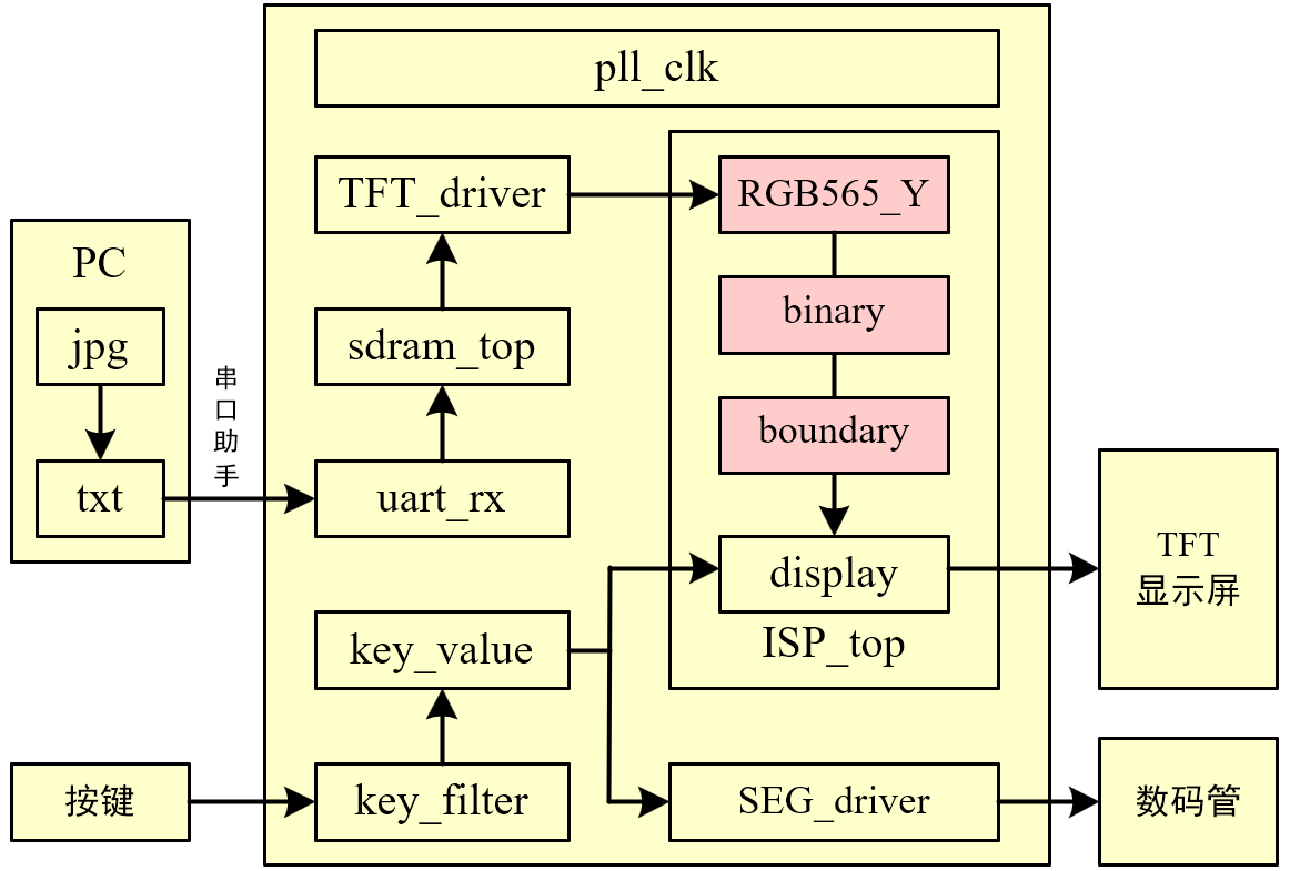
(1)ISP_top
//**************************************************************************
// *** 名称 : ISP_top.v
// *** 作者 : xianyu_FPGA
// *** 博客 : https://www.cnblogs.com/xianyufpga/
// *** 日期 : 2020年3月
// *** 描述 : 图像处理模块的顶层文件
//**************************************************************************

module ISP_top
//========================< 参数 >==========================================
#(
parameter H_DISP            = 12'd480               ,   //图像宽度
parameter V_DISP            = 12'd272                   //图像高度
)
//========================< 端口 >==========================================
(
input   wire                clk                     ,   //时钟
input   wire                rst_n                   ,   //复位
//RGB -----------------------------------------------
input   wire                RGB_hsync               ,   //RGB行同步
input   wire                RGB_vsync               ,   //RGB场同步
input   wire    [15:0]      RGB_data                ,   //RGB数据
input   wire                RGB_de                  ,   //RGB数据使能
//key -----------------------------------------------
input   wire    [ 1:0]      key_vld                 ,   //消抖后的按键值
//DISP ----------------------------------------------
output  wire                DISP_hsync              ,   //最终显示的行同步
output  wire                DISP_vsync              ,   //最终显示的场同步
output  wire    [15:0]      DISP_data               ,   //最终显示的数据
output  wire                DISP_de                     //最终显示的数据使能
);
//========================< 连线 >==========================================
//Y分量 ---------------------------------------------
wire                        Y_hsync                 ;   //Y分量行同步
wire                        Y_vsync                 ;   //Y分量场同步
wire    [ 7:0]              Y_data                  ;   //Y分量数据
wire                        Y_de                    ;   //Y分量数据使能
//bina ----------------------------------------------
wire                        bina_hsync              ;   //bina行同步
wire                        bina_vsync              ;   //bina场同步
wire    [ 7:0]              bina_data               ;   //bina数据
wire                        bina_de                 ;   //bina数据使能
//boundary ------------------------------------------
wire                        boundary_hsync          ;   //boundary行同步
wire                        boundary_vsync          ;   //boundary场同步
wire    [ 7:0]              boundary_data           ;   //boundary数据
wire                        boundary_de             ;   //boundary数据使能
//==========================================================================
//==            RGB565转YCbCr444,再取Y分量作为灰度数据
//==========================================================================
RGB565_Y u_RGB565_Y
(
    .clk                    (clk                    ),  //时钟
    .rst_n                  (rst_n                  ),  //复位
    //RGB -------------------------------------------
    .RGB_hsync              (RGB_hsync              ),  //RGB行同步
    .RGB_vsync              (RGB_vsync              ),  //RGB场同步
    .RGB_data               (RGB_data               ),  //RGB数据
    .RGB_de                 (RGB_de                 ),  //RGB数据使能
    //Y分量 -----------------------------------------
    .Y_hsync                (Y_hsync                ),  //Y分量行同步
    .Y_vsync                (Y_vsync                ),  //Y分量场同步
    .Y_data                 (Y_data                 ),  //Y分量数据
    .Y_de                   (Y_de                   )   //Y分量数据使能
);
//==========================================================================
//==                        灰度图转二值图
//==========================================================================
binary u_binary
(
    .clk                    (clk                    ),  //时钟
    .rst_n                  (rst_n                  ),  //复位
    //Y分量 -----------------------------------------
    .Y_hsync                (Y_hsync                ),  //Y分量行同步
    .Y_vsync                (Y_vsync                ),  //Y分量场同步
    .Y_data                 (Y_data                 ),  //Y分量数据
    .Y_de                   (Y_de                   ),  //Y分量数据使能
    //阈值 ------------------------------------------
    .value                  (8'd127                 ),  //阈值
    //bina ------------------------------------------
    .bina_hsync             (bina_hsync             ),  //bina行同步
    .bina_vsync             (bina_vsync             ),  //bina场同步
    .bina_data              (bina_data              ),  //bina数据
    .bina_de                (bina_de                )   //bina数据使能
);
//==========================================================================
//==                        二值法边缘检测
//==========================================================================
boundary
#(
    .H_DISP                 (H_DISP                 ),  //图像宽度
    .V_DISP                 (V_DISP                 )   //图像高度
)
u_boundary
(
    .clk                    (clk                    ),  //时钟
    .rst_n                  (rst_n                  ),  //复位
    //bina ------------------------------------------
    .bina_hsync             (bina_hsync             ),  //bina行同步
    .bina_vsync             (bina_vsync             ),  //bina场同步
    .bina_data              (bina_data              ),  //bina数据
    .bina_de                (bina_de                ),  //bina数据使能
    //boundary ----------------------------------------
    .boundary_hsync         (boundary_hsync         ),  //boundary行同步
    .boundary_vsync         (boundary_vsync         ),  //boundary场同步
    .boundary_data          (boundary_data          ),  //boundary数据
    .boundary_de            (boundary_de            )   //boundary数据使能
);
//==========================================================================
//==                        按键选择不同图像效果
//==========================================================================
display u_display
(
    .clk                    (clk                    ),  //时钟
    .rst_n                  (rst_n                  ),  //复位
    //pre -------------------------------------------
    .pre_hsync              (bina_hsync             ),  //pre行同步
    .pre_vsync              (bina_vsync             ),  //pre场同步
    .pre_data               ({bina_data[7:3],bina_data[7:2],bina_data[7:3]}),  //pre数据
    .pre_de                 (bina_de                ),  //pre数据使能
    //post ------------------------------------------
    .post_hsync             (boundary_hsync         ),  //post行同步
    .post_vsync             (boundary_vsync         ),  //post场同步
    .post_data              ({boundary_data[7:3],boundary_data[7:2],boundary_data[7:3]}),  //post数据
    .post_de                (boundary_de            ),  //post数据使能
    //key -------------------------------------------
    .key_vld                (key_vld                ),  //消抖后的按键值
    //DISP ------------------------------------------
    .DISP_hsync             (DISP_hsync             ),  //最终显示的行同步
    .DISP_data              (DISP_data              ),  //最终显示的场同步
    .DISP_de                (DISP_de                ),  //最终显示的数据
    .DISP_vsync             (DISP_vsync             )   //最终显示的数据使能
);


endmodule
(2)RGB565_Y
//**************************************************************************
// *** 名称 : RGB565_Y.v
// *** 作者 : xianyu_FPGA
// *** 博客 : https://www.cnblogs.com/xianyufpga/
// *** 日期 : 2020年3月
// *** 描述 : RGB565转RGB888再转YCbCr444,再取Y分量作为灰度数据
//--------------------------------------------------------------------------
//        Y   =   0.299*R + 0.587*G + 0.114*B
//        Cb  =   0.586*(B-Y) + 128 = -0.172*R - 0.339*G + 0.511*B + 128
//        Cr  =   0.713*(R-Y) + 128 =  0.511*R - 0.428*G - 0.083*B + 128
// --->
//        Y   =   ( 77*R  +  150*G  +   29*B) >> 8
//        Cb  =   (-43*R  -   85*G  +  128*B) >> 8 + 128
//        Cr  =   (128*R  -  107*G  -   21*B) >> 8 + 128
// --->
//        Y   =   ( 77*R  +  150*G  +   29*B) >> 8
//        Cb  =   (-43*R  -   85*G  +  128*B + 32768) >> 8
//        Cr  =   (128*R  -  107*G  -   21*B + 32768) >> 8
//**************************************************************************

module RGB565_Y
//========================< 端口 >==========================================
(
input   wire                clk                     ,   //时钟
input   wire                rst_n                   ,   //复位
//input ---------------------------------------------
input   wire                RGB_hsync               ,   //RGB行同步
input   wire                RGB_vsync               ,   //RGB场同步
input   wire    [15:0]      RGB_data                ,   //RGB数据
input   wire                RGB_de                  ,   //RGB数据使能
//output --------------------------------------------
output  wire                Y_hsync                 ,   //Y分量行同步
output  wire                Y_vsync                 ,   //Y分量场同步
output  wire    [ 7:0]      Y_data                  ,   //Y分量数据
output  wire                Y_de                        //Y分量数据使能
);
//========================< 信号 >==========================================
wire    [ 7:0]              R0, G0, B0              ;
reg     [15:0]              R1, G1, B1              ;
reg     [15:0]              R2, G2, B2              ;
reg     [15:0]              R3, G3, B3              ;
reg     [15:0]              Y1, Cb1, Cr1            ;
reg     [ 7:0]              Y2, Cb2, Cr2            ;
//---------------------------------------------------
reg     [ 2:0]              RGB_de_r                ;
reg     [ 2:0]              RGB_hsync_r             ;
reg     [ 2:0]              RGB_vsync_r             ;
//==========================================================================
//==    RGB565转RGB888
//==========================================================================
assign R0 = {RGB_data[15:11],RGB_data[13:11]};
assign G0 = {RGB_data[10: 5],RGB_data[ 6: 5]};
assign B0 = {RGB_data[ 4: 0],RGB_data[ 2: 0]};
//==========================================================================
//==    RGB888转YCbCr
//==========================================================================
//clk 1
//---------------------------------------------------
always @(posedge clk or negedge rst_n) begin
    if(!rst_n)begin
        {R1,G1,B1} <= {16'd0, 16'd0, 16'd0};
        {R2,G2,B2} <= {16'd0, 16'd0, 16'd0};
        {R3,G3,B3} <= {16'd0, 16'd0, 16'd0};
    end
    else begin
        {R1,G1,B1} <= { {R0 * 16'd77},  {G0 * 16'd150}, {B0 * 16'd29 } };
        {R2,G2,B2} <= { {R0 * 16'd43},  {G0 * 16'd85},  {B0 * 16'd128} };
        {R3,G3,B3} <= { {R0 * 16'd128}, {G0 * 16'd107}, {B0 * 16'd21 } };
    end
end

//clk 2
//---------------------------------------------------
always @(posedge clk or negedge rst_n) begin
    if(!rst_n)begin
        Y1  <= 16'd0;
        Cb1 <= 16'd0;
        Cr1 <= 16'd0;
    end
    else begin
        Y1  <= R1 + G1 + B1;
        Cb1 <= B2 - R2 - G2 + 16'd32768; //128扩大256倍
        Cr1 <= R3 - G3 - B3 + 16'd32768; //128扩大256倍
    end
end

//clk 3,除以256即右移8位,即取高8位
//---------------------------------------------------
always @(posedge clk or negedge rst_n) begin
    if(!rst_n)begin
        Y2  <= 8'd0;
        Cb2 <= 8'd0;
        Cr2 <= 8'd0;
    end
    else begin
        Y2  <= Y1[15:8];
        Cb2 <= Cb1[15:8];
        Cr2 <= Cr1[15:8];
    end
end

assign Y_data = Y2; //只取Y分量输出
//==========================================================================
//==    信号同步
//==========================================================================
always @(posedge clk or negedge rst_n) begin
    if(!rst_n) begin
        RGB_de_r    <= 3'b0;
        RGB_hsync_r <= 3'b0;
        RGB_vsync_r <= 3'b0;
    end
    else begin
        RGB_de_r    <= {RGB_de_r[1:0],    RGB_de};
        RGB_hsync_r <= {RGB_hsync_r[1:0], RGB_hsync};
        RGB_vsync_r <= {RGB_vsync_r[1:0], RGB_vsync};
    end
end

assign Y_de    = RGB_de_r[2];
assign Y_hsync = RGB_hsync_r[2];
assign Y_vsync = RGB_vsync_r[2];


endmodule
(3)binary
//**************************************************************************
// *** 名称 : binary.v
// *** 作者 : xianyu_FPGA
// *** 博客 : https://www.cnblogs.com/xianyufpga/
// *** 日期 : 2020年3月
// *** 描述 : Gray灰度图转二值图
//**************************************************************************
module binary
//========================< 端口 >==========================================
(
input   wire                clk                     ,   //时钟
input   wire                rst_n                   ,   //复位
//原图 ----------------------------------------------
input   wire                Y_hsync                 ,   //Y分量行同步
input   wire                Y_vsync                 ,   //Y分量场同步
input   wire    [ 7:0]      Y_data                  ,   //Y分量数据
input   wire                Y_de                    ,   //Y分量数据使能
//value ---------------------------------------------
input   wire    [ 7:0]      value                   ,   //阈值
//灰度 ----------------------------------------------
output  wire                bina_hsync              ,   //二值行同步
output  wire                bina_vsync              ,   //二值场同步
output  wire    [ 7:0]      bina_data               ,   //二值数据
output  wire                bina_de                     //二值数据使能
);
//==========================================================================
//==                        代码
//==========================================================================
assign bina_hsync = Y_hsync;
assign bina_vsync = Y_vsync;
assign bina_de    = Y_de;
assign bina_data  = (Y_data > value) ? 8'hff : 8'h00;


endmodule
(4)boundary
//**************************************************************************
// *** 名称 : boundary.v
// *** 作者 : xianyu_FPGA
// *** 博客 : https://www.cnblogs.com/xianyufpga/
// *** 日期 : 2020年3月
// *** 描述 : boundary边缘检测,输入必须是二值化图像
//**************************************************************************

module boundary
//========================< 参数 >==========================================
#(
parameter H_DISP            = 12'd480               ,   //图像宽度
parameter V_DISP            = 12'd272                   //图像高度
)
//========================< 端口 >==========================================
(
input   wire                clk                     ,   //时钟
input   wire                rst_n                   ,   //复位
//input ---------------------------------------------
input   wire                bina_hsync              ,   //bina场同步
input   wire                bina_vsync              ,   //bina数据
input   wire    [ 7:0]      bina_data               ,   //bina数据使能
input   wire                bina_de                 ,   //bina行同步
//output --------------------------------------------
output  wire                boundary_hsync          ,   //boundary场同步
output  wire                boundary_vsync          ,   //boundary数据
output  reg     [ 7:0]      boundary_data           ,   //boundary数据使能
output  wire                boundary_de                 //boundary行同步
);
//========================< 信号 >==========================================
//matrix_3x3 ----------------------------------------
wire    [ 7:0]              matrix_11               ;
wire    [ 7:0]              matrix_12               ;
wire    [ 7:0]              matrix_13               ;
wire    [ 7:0]              matrix_21               ;
wire    [ 7:0]              matrix_22               ;
wire    [ 7:0]              matrix_23               ;
wire    [ 7:0]              matrix_31               ;
wire    [ 7:0]              matrix_32               ;
wire    [ 7:0]              matrix_33               ;
//同步 ----------------------------------------------
reg     [ 1:0]              bina_de_r               ;
reg     [ 1:0]              bina_hsync_r            ;
reg     [ 1:0]              bina_vsync_r            ;
//==========================================================================
//==    matrix_3x3_8bit,生成3x3矩阵,输入和使能需对齐,耗费1clk
//==========================================================================
//--------------------------------------------------- 矩阵顺序
//        {matrix_11, matrix_12, matrix_13}
//        {matrix_21, matrix_22, matrix_23}
//        {matrix_31, matrix_32, matrix_33}
//--------------------------------------------------- 模块例化
matrix_3x3_8bit
#(
    .H_DISP                 (H_DISP                 ),  //图像宽度
    .V_DISP                 (V_DISP                 )   //图像高度
)
u_matrix_3x3_16bit
(
    .clk                    (clk                    ),
    .rst_n                  (rst_n                  ),
    .din_vld                (bina_de                ),
    .din                    (bina_data              ),
    .matrix_11              (matrix_11              ),
    .matrix_12              (matrix_12              ),
    .matrix_13              (matrix_13              ),
    .matrix_21              (matrix_21              ),
    .matrix_22              (matrix_22              ),
    .matrix_23              (matrix_23              ),
    .matrix_31              (matrix_31              ),
    .matrix_32              (matrix_32              ),
    .matrix_33              (matrix_33              )
);
//==========================================================================
//==    边缘提取,耗费1clk
//==========================================================================
always @ (posedge clk or negedge rst_n)begin
    if(!rst_n)begin
        boundary_data <= 8'h0;
    end
    else if((matrix_11 == 8'h0) && (matrix_12 == 8'h0) && (matrix_13 == 8'h0) &&
            (matrix_21 == 8'h0) && (matrix_22 == 8'h0) && (matrix_23 == 8'h0) &&
            (matrix_31 == 8'h0) && (matrix_32 == 8'h0) && (matrix_33 == 8'h0))
            begin
        boundary_data <= 8'hff;
    end
    else if((matrix_11 == 8'hff) && (matrix_12 == 8'hff) && (matrix_13 == 8'hff) &&
            (matrix_21 == 8'hff) && (matrix_22 == 8'hff) && (matrix_23 == 8'hff) &&
            (matrix_31 == 8'hff) && (matrix_32 == 8'hff) && (matrix_33 == 8'hff))
            begin
        boundary_data <= 8'hff;
    end
    else begin
        boundary_data <= 8'h0;
    end
end
//==========================================================================
//==    信号同步
//==========================================================================
always @(posedge clk or negedge rst_n) begin
    if(!rst_n) begin
        bina_de_r    <= 2'b0;
        bina_hsync_r <= 2'b0;
        bina_vsync_r <= 2'b0;
    end
    else begin
        bina_de_r    <= {bina_de_r[0],    bina_de};
        bina_hsync_r <= {bina_hsync_r[0], bina_hsync};
        bina_vsync_r <= {bina_vsync_r[0], bina_vsync};
    end
end

assign boundary_de    = bina_de_r[1];
assign boundary_hsync = bina_hsync_r[1];
assign boundary_vsync = bina_vsync_r[1];


endmodule
//**************************************************************************
// *** 名称 : matrix_3x3_8bit.v
// *** 作者 : xianyu_FPGA
// *** 博客 : https://www.cnblogs.com/xianyufpga/
// *** 日期 : 2020年3月
// *** 描述 : 3x3矩阵,边界采用像素复制,最大支持1024x1024,耗费1clk
//**************************************************************************
module matrix_3x3_8bit
//========================< 参数 >==========================================
#(
parameter H_DISP = 12'd480 , //图像宽度
parameter V_DISP = 12'd272 //图像高度
)
//========================< 端口 >==========================================
(
input wire clk ,
input wire rst_n ,
//input ---------------------------------------------
input wire din_vld ,
input wire [ 7:0] din ,
//output --------------------------------------------
output reg [ 7:0] matrix_11 ,
output reg [ 7:0] matrix_12 ,
output reg [ 7:0] matrix_13 ,
output reg [ 7:0] matrix_21 ,
output reg [ 7:0] matrix_22 ,
output reg [ 7:0] matrix_23 ,
output reg [ 7:0] matrix_31 ,
output reg [ 7:0] matrix_32 ,
output reg [ 7:0] matrix_33
);
//========================< 信号 >==========================================
reg [11:0] cnt_col ;
wire add_cnt_col ;
wire end_cnt_col ;
reg [11:0] cnt_row ;
wire add_cnt_row ;
wire end_cnt_row ;
wire wr_en_1 ;
wire wr_en_2 ;
wire rd_en_1 ;
wire rd_en_2 ;
wire [ 7:0] q_1 ;
wire [ 7:0] q_2 ;
wire [ 7:0] row_1 ;
wire [ 7:0] row_2 ;
wire [ 7:0] row_3 ;
//==========================================================================
//== FIFO例化,show模式,深度为大于两行数据个数
//==========================================================================
fifo_show_2048x8 u1
(
.clock (clk ),
.data (din ),
.wrreq (wr_en_1 ),
.rdreq (rd_en_1 ),
.q (q_1 )
);
fifo_show_2048x8 u2
(
.clock (clk ),
.data (din ),
.wrreq (wr_en_2 ),
.rdreq (rd_en_2 ),
.q (q_2 )
);
//==========================================================================
//== 行列划分
//==========================================================================
always @(posedge clk or negedge rst_n) begin
if(!rst_n)
cnt_col <= 12'd0;
else if(add_cnt_col) begin
if(end_cnt_col)
cnt_col <= 12'd0;
else
cnt_col <= cnt_col + 12'd1;
end
end
assign add_cnt_col = din_vld;
assign end_cnt_col = add_cnt_col && cnt_col== H_DISP-12'd1;
always @(posedge clk or negedge rst_n) begin
if(!rst_n)
cnt_row <= 12'd0;
else if(add_cnt_row) begin
if(end_cnt_row)
cnt_row <= 12'd0;
else
cnt_row <= cnt_row + 12'd1;
end
end
assign add_cnt_row = end_cnt_col;
assign end_cnt_row = add_cnt_row && cnt_row== V_DISP-12'd1;
//==========================================================================
//== fifo 读写信号
//==========================================================================
assign wr_en_1 = (cnt_row < V_DISP - 12'd1) ? din_vld : 1'd0; //不写最后1行
assign rd_en_1 = (cnt_row > 12'd0 ) ? din_vld : 1'd0; //从第1行开始读
assign wr_en_2 = (cnt_row < V_DISP - 12'd2) ? din_vld : 1'd0; //不写最后2行
assign rd_en_2 = (cnt_row > 12'd1 ) ? din_vld : 1'd0; //从第2行开始读
//==========================================================================
//== 形成 3x3 矩阵,边界采用像素复制
//==========================================================================
//矩阵数据选取
//---------------------------------------------------
assign row_1 = q_2;
assign row_2 = q_1;
assign row_3 = din;
//打拍形成矩阵,1clk
//---------------------------------------------------
always @(posedge clk or negedge rst_n) begin
if(!rst_n) begin
{matrix_11, matrix_12, matrix_13} <= {8'd0, 8'd0, 8'd0};
{matrix_21, matrix_22, matrix_23} <= {8'd0, 8'd0, 8'd0};
{matrix_31, matrix_32, matrix_33} <= {8'd0, 8'd0, 8'd0};
end
//------------------------------------------------------------------------- 第1排矩阵
else if(cnt_row == 12'd0) begin
if(cnt_col == 12'd0) begin //第1个矩阵
{matrix_11, matrix_12, matrix_13} <= {row_3, row_3, row_3};
{matrix_21, matrix_22, matrix_23} <= {row_3, row_3, row_3};
{matrix_31, matrix_32, matrix_33} <= {row_3, row_3, row_3};
end
else begin //剩余矩阵
{matrix_11, matrix_12, matrix_13} <= {matrix_12, matrix_13, row_3};
{matrix_21, matrix_22, matrix_23} <= {matrix_22, matrix_23, row_3};
{matrix_31, matrix_32, matrix_33} <= {matrix_32, matrix_33, row_3};
end
end
//------------------------------------------------------------------------- 第2排矩阵
else if(cnt_row == 12'd1) begin
if(cnt_col == 12'd0) begin //第1个矩阵
{matrix_11, matrix_12, matrix_13} <= {row_2, row_2, row_2};
{matrix_21, matrix_22, matrix_23} <= {row_2, row_2, row_2};
{matrix_31, matrix_32, matrix_33} <= {row_3, row_3, row_3};
end
else begin //剩余矩阵
{matrix_11, matrix_12, matrix_13} <= {matrix_12, matrix_13, row_2};
{matrix_21, matrix_22, matrix_23} <= {matrix_22, matrix_23, row_2};
{matrix_31, matrix_32, matrix_33} <= {matrix_32, matrix_33, row_3};
end
end
//------------------------------------------------------------------------- 剩余矩阵
else begin
if(cnt_col == 12'd0) begin //第1个矩阵
{matrix_11, matrix_12, matrix_13} <= {row_1, row_1, row_1};
{matrix_21, matrix_22, matrix_23} <= {row_2, row_2, row_2};
{matrix_31, matrix_32, matrix_33} <= {row_3, row_3, row_3};
end
else begin //剩余矩阵
{matrix_11, matrix_12, matrix_13} <= {matrix_12, matrix_13, row_1};
{matrix_21, matrix_22, matrix_23} <= {matrix_22, matrix_23, row_2};
{matrix_31, matrix_32, matrix_33} <= {matrix_32, matrix_33, row_3};
end
end
end
endmodule(5)display
//**************************************************************************
// *** 名称 : display.v
// *** 作者 : xianyu_FPGA
// *** 博客 : https://www.cnblogs.com/xianyufpga/
// *** 日期 : 2020年3月
// *** 描述 : 按键切换不同的图像效果
//**************************************************************************

module display
//========================< 端口 >==========================================
(
input   wire                clk                     ,   //时钟
input   wire                rst_n                   ,   //复位
//pre -----------------------------------------------
input   wire                pre_hsync               ,   //pre行同步
input   wire                pre_vsync               ,   //pre场同步
input   wire    [15:0]      pre_data                ,   //pre数据
input   wire                pre_de                  ,   //pre数据使能
//post ----------------------------------------------
input   wire                post_hsync              ,   //post行同步
input   wire                post_vsync              ,   //post场同步
input   wire    [15:0]      post_data               ,   //post数据
input   wire                post_de                 ,   //post数据使能
//key -----------------------------------------------
input   wire    [ 1:0]      key_vld                 ,   //消抖后的按键值
//DISP ----------------------------------------------
output  reg                 DISP_hsync              ,   //最终显示的行同步
output  reg                 DISP_vsync              ,   //最终显示的场同步
output  reg     [15:0]      DISP_data               ,   //最终显示的数据
output  reg                 DISP_de                     //最终显示的数据使能
);
//========================< 信号 >==========================================
reg                         mode                    ;   //模式切换
//==========================================================================
//==    按键切换不同显示效果
//==========================================================================
always @(posedge clk or negedge rst_n) begin
    if(!rst_n) begin
        mode <= 1'b0;
    end
    else if(key_vld[0]) begin
        mode <= 1'b1;
    end
    else if(key_vld[1]) begin
        mode <= 1'b0;
    end
end

always @(posedge clk or negedge rst_n) begin
    if(!rst_n) begin
        DISP_hsync <= 0;
        DISP_vsync <= 0;
        DISP_data  <= 0;
        DISP_de    <= 0;
    end
    else if(mode==1'b0) begin   //pre
        DISP_hsync <= pre_hsync;
        DISP_vsync <= pre_vsync;
        DISP_data  <= pre_data;
        DISP_de    <= pre_de;
    end
    else if(mode==1'b1) begin   //post
        DISP_hsync <= post_hsync;
        DISP_vsync <= post_vsync;
        DISP_data  <= post_data;
        DISP_de    <= post_de;
    end
end


endmodule
二、上板验证
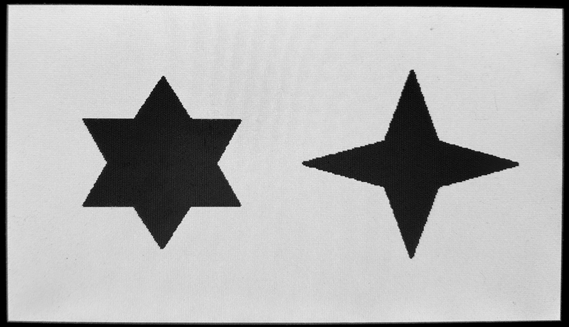
输入找了张二值图片,如果没有二值图片,可以在边界提取前自己写一下阈值判断即可。
二值原图:
边界提取后:
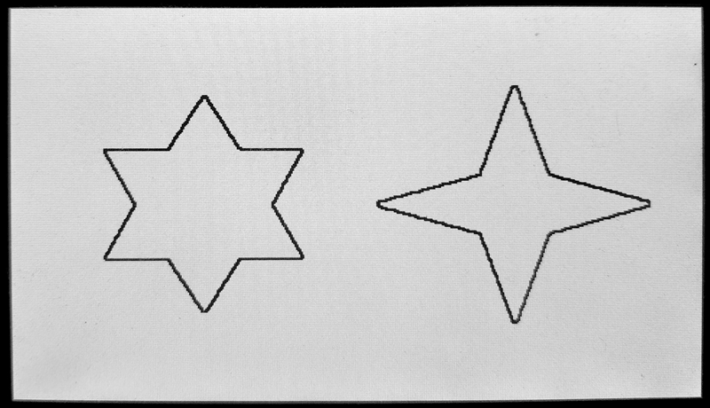
由实验结果可知,边界提取成功,外部的白色和内部的黑色都变为了白色,只有边界处是黑色。
参考资料:[1] Opens Lee:FPGA开源工作室(公众号)

 浙公网安备 33010602011771号