
FPGA实现图像的边缘检测:Sobel算子
“边缘检测是图像处理和计算机视觉中的基本问题,边缘检测的目的是标识数字图像中亮度变化明显的点。图像属性中的显著变化通常反映了属性的重要事件和变化。 这些包括(i)深度上的不连续、(ii)表面方向不连续、(iii)物质属性变化和(iv)场景照明变化。 边缘检测是图像处理和计算机视觉中,尤其是特征提取中的一个研究领域。图像边缘检测大幅度地减少了数据量,并且剔除了可以认为不相关的信息,保留了图像重要的结构属性。常用的边缘检测模板有Laplacian算子、Roberts算子、Sobel算子、log(Laplacian-Gauss)算子、Kirsch算子和Prewitt算子等。”
——百度百科《边缘检测》
Sobel算子是常用的边缘检测模板,算法比较简单,实际应用中效率比 canny 边缘检测效率要高,但是边缘不如 Canny 检测的准确,但是很多实际应用的场合,Sobel 边缘却是首选,尤其是对效率要求较高,而对细纹理不太关心的时候。在技术上,Sobel 算子是一离散性差分算子,用来运算图像亮度函数的灰度之近似值。在图像的任何一点使用此算子,将会产生对应的灰度矢量或是其法矢量。Sobel 边缘检测通常带有方向性,可以只检测竖直边缘或垂直边缘或都检测。
Sobel边缘检测的核心在于像素矩阵的卷积,卷积对于数字图像处理非常重要,很多图像处理算法都是做卷积来实现的。卷积运算的本质就是对指定的图像区域的像素值进行加权求和的过程,其计算过程为图像区域中的每个像素值分别与卷积模板的每个元素对应相乘,将卷积的结果作求和运算,运算到的和就是卷积运算的结果。矩阵的卷积公式如下:
......我也没怎么看明白这公式,继续往下看吧。
一、实现步骤
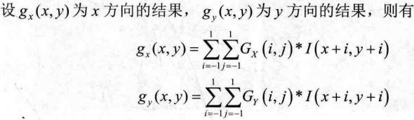
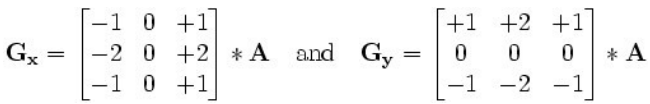
1、Sobel 提供了水平方向和垂直方向两个方向的滤波模板。设 x 方向和 y 方向的卷积因子分别为 Gx 和 Gy,模板如下所示,A为原图像。
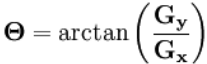
2、矩阵运算后,就得到横向灰度值 Gx 和纵向灰度值 Gy,然后通过如下公式进行计算出该点的灰度值:
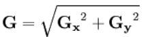
这个运算比较复杂,开方又开根的,可以取近视值替代,影响也不大:
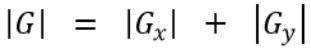
3、最后,设置一个阈值 value,对数据进行比较然后输出二值图像:
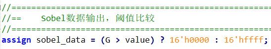
很多书上说的计算梯度方向,其实就是上面的 |G|。
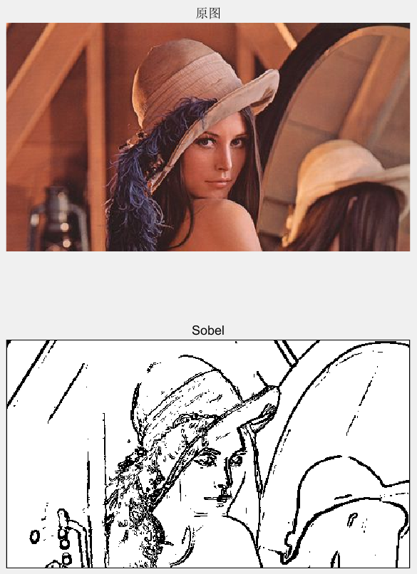
二、MATLAB实现
clc;
clear all;
close all;

RGB = imread('Lenna.jpg');        %读取图片
gray = double(rgb2gray(RGB));     %灰度图
[ROW,COL, DIM] = size(gray);      %得到图像行列数
value = 120;                      %阈值设置
Sobel_img = zeros(ROW,COL);

for r = 2:ROW-1
    for c = 2:COL-1
        Gx = gray(r-1,c+1) + 2*gray(r,c+1) + gray(r+1,c+1) - gray(r-1,c-1) - 2*gray(r,c-1) - gray(r+1,c-1);
        Gy = gray(r-1,c-1) + 2*gray(r-1,c) + gray(r-1,c+1) - gray(r+1,c-1) - 2*gray(r+1,c) - gray(r+1,c+1);
        G = abs(Gx) + abs(Gy);
        %G = sqrt(Gx^2 + Gy^2);
        if(G > value)
            Sobel_img(r,c)=0;
        else
            Sobel_img(r,c)=255;
        end
    end
end

subplot(2,1,1); imshow(RGB);      title('原图');
subplot(2,1,2); imshow(Sobel_img);title('Sobel');
点击运行,得到如下结果:
三、FPGA实现
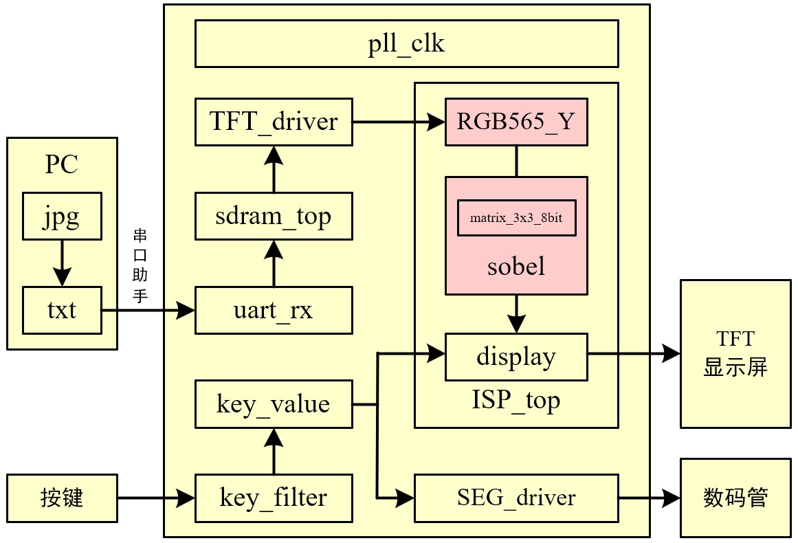
1、形成3x3矩阵
这个在前面的博客花了3篇来解释,就不多说了,我把3x3矩阵的代码用一个专门的 .v 文件写好,这里直接调用即可。输入是灰度数据,即 YCbCr格式中的 8bit Y分量,输出是矩阵数据。耗费 1 个时钟周期。
//**************************************************************************
// *** 名称 : matrix_3x3_8bit.v
// *** 作者 : xianyu_FPGA
// *** 博客 : https://www.cnblogs.com/xianyufpga/
// *** 日期 : 2020年3月
// *** 描述 : 3x3矩阵,边界采用像素复制,最大支持1024x1024,耗费1clk
//**************************************************************************

module matrix_3x3_8bit
//========================< 参数 >==========================================
#(
parameter H_DISP            = 12'd480               ,   //图像宽度
parameter V_DISP            = 12'd272                   //图像高度
)
//========================< 端口 >==========================================
(
input   wire                clk                     ,
input   wire                rst_n                   ,
//input ---------------------------------------------
input   wire                din_vld                 ,
input   wire    [ 7:0]      din                     ,
//output --------------------------------------------
output  reg     [ 7:0]      matrix_11               ,
output  reg     [ 7:0]      matrix_12               ,
output  reg     [ 7:0]      matrix_13               ,
output  reg     [ 7:0]      matrix_21               ,
output  reg     [ 7:0]      matrix_22               ,
output  reg     [ 7:0]      matrix_23               ,
output  reg     [ 7:0]      matrix_31               ,
output  reg     [ 7:0]      matrix_32               ,
output  reg     [ 7:0]      matrix_33
);
//========================< 信号 >==========================================
reg     [11:0]              cnt_col                 ;
wire                        add_cnt_col             ;
wire                        end_cnt_col             ;
reg     [11:0]              cnt_row                 ;
wire                        add_cnt_row             ;
wire                        end_cnt_row             ;
wire                        wr_en_1                 ;
wire                        wr_en_2                 ;
wire                        rd_en_1                 ;
wire                        rd_en_2                 ;
wire    [ 7:0]              q_1                     ;
wire    [ 7:0]              q_2                     ;
wire    [ 7:0]              row_1                   ;
wire    [ 7:0]              row_2                   ;
wire    [ 7:0]              row_3                   ;
//==========================================================================
//==    FIFO例化,show模式,深度为大于两行数据个数
//==========================================================================
fifo_show_2048x8 u1
(
    .clock                  (clk                    ),
    .data                   (din                    ),
    .wrreq                  (wr_en_1                ),
    .rdreq                  (rd_en_1                ),
    .q                      (q_1                    )
);

fifo_show_2048x8 u2
(
    .clock                  (clk                    ),
    .data                   (din                    ),
    .wrreq                  (wr_en_2                ),
    .rdreq                  (rd_en_2                ),
    .q                      (q_2                    )
);
//==========================================================================
//==    行列划分
//==========================================================================
always @(posedge clk or negedge rst_n) begin
    if(!rst_n)
        cnt_col <= 12'd0;
    else if(add_cnt_col) begin
        if(end_cnt_col)
            cnt_col <= 12'd0;
        else
            cnt_col <= cnt_col + 12'd1;
    end
end

assign add_cnt_col = din_vld;
assign end_cnt_col = add_cnt_col && cnt_col== H_DISP-12'd1;

always @(posedge clk or negedge rst_n) begin
    if(!rst_n)
        cnt_row <= 12'd0;
    else if(add_cnt_row) begin
        if(end_cnt_row)
            cnt_row <= 12'd0;
        else
            cnt_row <= cnt_row + 12'd1;
    end
end

assign add_cnt_row = end_cnt_col;
assign end_cnt_row = add_cnt_row && cnt_row== V_DISP-12'd1;
//==========================================================================
//==    fifo 读写信号
//==========================================================================
assign wr_en_1 = (cnt_row < V_DISP - 12'd1) ? din_vld : 1'd0; //不写最后1行
assign rd_en_1 = (cnt_row > 12'd0         ) ? din_vld : 1'd0; //从第1行开始读
assign wr_en_2 = (cnt_row < V_DISP - 12'd2) ? din_vld : 1'd0; //不写最后2行
assign rd_en_2 = (cnt_row > 12'd1         ) ? din_vld : 1'd0; //从第2行开始读
//==========================================================================
//==    形成 3x3 矩阵,边界采用像素复制
//==========================================================================
//矩阵数据选取
//---------------------------------------------------
assign row_1 = q_2;
assign row_2 = q_1;
assign row_3 = din;

//打拍形成矩阵,1clk
//---------------------------------------------------
always @(posedge clk or negedge rst_n) begin
    if(!rst_n) begin
        {matrix_11, matrix_12, matrix_13} <= {8'd0, 8'd0, 8'd0};
        {matrix_21, matrix_22, matrix_23} <= {8'd0, 8'd0, 8'd0};
        {matrix_31, matrix_32, matrix_33} <= {8'd0, 8'd0, 8'd0};
    end
    //------------------------------------------------------------------------- 第1排矩阵
    else if(cnt_row == 12'd0) begin
        if(cnt_col == 12'd0) begin          //第1个矩阵
            {matrix_11, matrix_12, matrix_13} <= {row_3, row_3, row_3};
            {matrix_21, matrix_22, matrix_23} <= {row_3, row_3, row_3};
            {matrix_31, matrix_32, matrix_33} <= {row_3, row_3, row_3};
        end
        else begin                          //剩余矩阵
            {matrix_11, matrix_12, matrix_13} <= {matrix_12, matrix_13, row_3};
            {matrix_21, matrix_22, matrix_23} <= {matrix_22, matrix_23, row_3};
            {matrix_31, matrix_32, matrix_33} <= {matrix_32, matrix_33, row_3};
        end
    end
    //------------------------------------------------------------------------- 第2排矩阵
    else if(cnt_row == 12'd1) begin
        if(cnt_col == 12'd0) begin          //第1个矩阵
            {matrix_11, matrix_12, matrix_13} <= {row_2, row_2, row_2};
            {matrix_21, matrix_22, matrix_23} <= {row_2, row_2, row_2};
            {matrix_31, matrix_32, matrix_33} <= {row_3, row_3, row_3};
        end
        else begin                          //剩余矩阵
            {matrix_11, matrix_12, matrix_13} <= {matrix_12, matrix_13, row_2};
            {matrix_21, matrix_22, matrix_23} <= {matrix_22, matrix_23, row_2};
            {matrix_31, matrix_32, matrix_33} <= {matrix_32, matrix_33, row_3};
        end
    end
    //------------------------------------------------------------------------- 剩余矩阵
    else begin
        if(cnt_col == 12'd0) begin          //第1个矩阵
            {matrix_11, matrix_12, matrix_13} <= {row_1, row_1, row_1};
            {matrix_21, matrix_22, matrix_23} <= {row_2, row_2, row_2};
            {matrix_31, matrix_32, matrix_33} <= {row_3, row_3, row_3};
        end
        else begin                          //剩余矩阵
            {matrix_11, matrix_12, matrix_13} <= {matrix_12, matrix_13, row_1};
            {matrix_21, matrix_22, matrix_23} <= {matrix_22, matrix_23, row_2};
            {matrix_31, matrix_32, matrix_33} <= {matrix_32, matrix_33, row_3};
        end
    end
end


endmodule
2、Sobel算子
按上面步骤进行流水线计算即可,value的值可以直接写参数表示,可以直接写数字,也可以外部信号引入。耗费 3 个时钟周期。
//**************************************************************************
// *** 名称 : Sobel.v
// *** 作者 : xianyu_FPGA
// *** 博客 : https://www.cnblogs.com/xianyufpga/
// *** 日期 : 2020年3月
// *** 描述 : Y分量进行Sobel处理
//**************************************************************************

module sobel
//========================< 参数 >==========================================
#(
parameter H_DISP            = 12'd480               ,   //图像宽度
parameter V_DISP            = 12'd272                   //图像高度
)
//========================< 端口 >==========================================
(
input   wire                clk                     ,   //时钟
input   wire                rst_n                   ,   //复位
//input ---------------------------------------------
input   wire                Y_de                    ,   //Y分量行同步
input   wire                Y_hsync                 ,   //Y分量场同步
input   wire                Y_vsync                 ,   //Y分量数据
input   wire    [ 7:0]      Y_data                  ,   //Y分量数据使能
//key -----------------------------------------------
input   wire    [ 7:0]      value                   ,   //sobel阈值
//output --------------------------------------------
output  wire                sobel_de                ,   //sobel行同步
output  wire                sobel_hsync             ,   //sobel场同步
output  wire                sobel_vsync             ,   //sobel数据
output  wire    [ 7:0]      sobel_data                  //sobel数据使能
);
//========================< 信号 >==========================================
//matrix_3x3 ----------------------------------------
wire    [ 7:0]              matrix_11               ;
wire    [ 7:0]              matrix_12               ;
wire    [ 7:0]              matrix_13               ;
wire    [ 7:0]              matrix_21               ;
wire    [ 7:0]              matrix_22               ;
wire    [ 7:0]              matrix_23               ;
wire    [ 7:0]              matrix_31               ;
wire    [ 7:0]              matrix_32               ;
wire    [ 7:0]              matrix_33               ;
//sobel ---------------------------------------------
reg     [ 9:0]              Gx1,Gx3,Gy1,Gy3,Gx,Gy   ;
reg     [10:0]              G                       ;
//同步 ----------------------------------------------
reg     [ 3:0]              Y_de_r                  ;
reg     [ 3:0]              Y_hsync_r               ;
reg     [ 3:0]              Y_vsync_r               ;
//==========================================================================
//==    matrix_3x3_8bit,生成3x3矩阵,输入和使能需对齐,耗费1clk
//==========================================================================
//--------------------------------------------------- 矩阵顺序
//        {matrix_11, matrix_12, matrix_13}
//        {matrix_21, matrix_22, matrix_23}
//        {matrix_31, matrix_32, matrix_33}
//--------------------------------------------------- 模块例化
matrix_3x3_8bit
#(
    .H_DISP                 (H_DISP                 ),
    .V_DISP                 (V_DISP                 )
)
u_matrix_3x3_8bit
(
    .clk                    (clk                    ),
    .rst_n                  (rst_n                  ),
    .din_vld                (Y_de                   ),
    .din                    (Y_data                 ),
    .matrix_11              (matrix_11              ),
    .matrix_12              (matrix_12              ),
    .matrix_13              (matrix_13              ),
    .matrix_21              (matrix_21              ),
    .matrix_22              (matrix_22              ),
    .matrix_23              (matrix_23              ),
    .matrix_31              (matrix_31              ),
    .matrix_32              (matrix_32              ),
    .matrix_33              (matrix_33              )
);
//==========================================================================
//==    Sobel处理,耗费3clk
//==========================================================================
//clk1:Gx1、Gx3和Gy1、Gy3
//---------------------------------------------------
always @(posedge clk or negedge rst_n) begin
    if(!rst_n) begin
        Gx1 <= 'd0;
        Gx3 <= 'd0;
        Gy1 <= 'd0;
        Gy3 <= 'd0;
    end
    else begin
        Gx1 <= matrix_11 + (matrix_21 << 1) + matrix_31;
        Gx3 <= matrix_13 + (matrix_23 << 1) + matrix_33;
        Gy1 <= matrix_11 + (matrix_12 << 1) + matrix_13;
        Gy3 <= matrix_31 + (matrix_32 << 1) + matrix_33;
    end
end

//clk2:Gx和Gy绝对值
//---------------------------------------------------
always @(posedge clk or negedge rst_n) begin
    if(!rst_n) begin
        Gx <= 'd0;
        Gy <= 'd0;
    end
    else begin  //也可判断bit[7]来确定
        Gx <= (Gx1 > Gx3) ? (Gx1 - Gx3) : (Gx3 - Gx1);
        Gy <= (Gy1 > Gy3) ? (Gy1 - Gy3) : (Gy3 - Gy1);
    end
end

//clk3:Gx+Gy
//---------------------------------------------------
always @(posedge clk or negedge rst_n) begin
    if(!rst_n) begin
        G <= 'd0;
    end
    else begin
        G <= Gx + Gy;
    end
end

assign sobel_data = (G > value) ? 8'h00 : 8'hff;
//==========================================================================
//==    信号同步
//==========================================================================
always @(posedge clk or negedge rst_n) begin
    if(!rst_n) begin
        Y_de_r    <= 4'b0;
        Y_hsync_r <= 4'b0;
        Y_vsync_r <= 4'b0;
    end
    else begin
        Y_de_r    <= {Y_de_r[2:0],    Y_de};
        Y_hsync_r <= {Y_hsync_r[2:0], Y_hsync};
        Y_vsync_r <= {Y_vsync_r[2:0], Y_vsync};
    end
end

assign sobel_de    = Y_de_r[3];
assign sobel_hsync = Y_hsync_r[3];
assign sobel_vsync = Y_vsync_r[3];


endmodule
四、上板验证
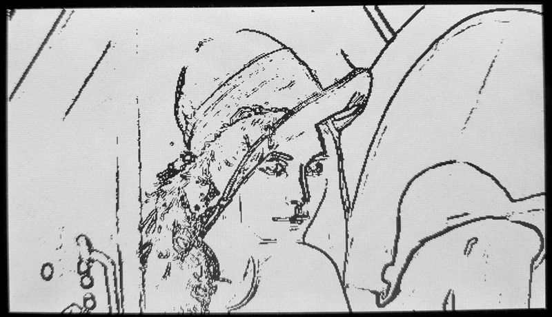
我的 value 阈值由外部按键给出,当阈值为120时,效果如下:
视频演示如下:
同样的,可以移植到 OV7670 摄像头工程中,如下所示:
[1] OpenS Lee:FPGA开源工作室(公众号)
[2] CrazyBingo:基于VIP_Board Mini的FPGA视频图像算法(HDL-VIP)开发教程-V1.6
[3] NingHechuan:FPGA图像处理教程
[4] 牟新刚、周晓、郑晓亮.基于FPGA的数字图像处理原理及应用[M]. 电子工业出版社,2017.
[5] 张铮, 王艳平, 薛桂香. 数字图像处理与机器视觉[M]. 人民邮电出版社, 2010.

 浙公网安备 33010602011771号