
FPGA实现图像几何变换:旋转
旋转一般是指将图像围绕某一指定点旋转一定的角度。 旋转通常也会改变图像的大小,和图像平移的处理一样,可以把转出显示区域的图像截去,也可以改变输出图像的大小以扩展显示范围。
本篇博客实现的旋转算法改编自上一篇博客的镜像,因此不说那么多理论,直接记录重点。
一、MATLAB实现
1、函数法
%--------------------------------------------------------------------------
%                       函数法旋转
%--------------------------------------------------------------------------
clc;
clear all;
RGB = imread('monkey.jpg'); %读取图像

L_rotate  = imrotate(RGB,90,'crop');
R_rotate  = imrotate(RGB,-90,'crop');
rotate    = imrotate(RGB,180,'crop');

subplot(2,2,1),imshow(RGB);      title('原图');
subplot(2,2,2),imshow(L_rotate); title('水平镜像');
subplot(2,2,3),imshow(R_rotate); title('垂直镜像');
subplot(2,2,4),imshow(rotate);title('水平垂直镜像');
运行结果:

2、公式法
%--------------------------------------------------------------------------
%                       公式法旋转
%--------------------------------------------------------------------------
clc;
clear all;
RGB = imread('monkey.jpg'); %读取图像

[ROW,COL,N] = size(RGB);

L_rotate  = uint8(zeros(ROW, COL,N)); %Left  rotate
R_rotate  = uint8(zeros(ROW, COL,N)); %Right rotate
rotate    = uint8(zeros(ROW, COL,N)); %180° rotate

%左转90度
for i =1:ROW
    for j=1:COL
        for k=1:N
            x = COL-j+1;
            y = i;
            z = k;
            L_rotate(x,y,z) =RGB(i,j,k);
        end
    end
end

%右转90度
for i =1:ROW
    for j=1:COL
        for k=1:N
            x = j;
            y = ROW-i+1;
            z = k;
            R_rotate(x,y,z) =RGB(i,j,k);
        end
    end
end

%旋转180度
for i =1:ROW
    for j=1:COL
        for k=1:N
            x = ROW-i+1;
            y = COL-j+1;
            z = k;
            rotate(x,y,z) =RGB(i,j,k);
        end
    end
end

subplot(2,2,1),imshow(RGB);      title('原图');
subplot(2,2,2),imshow(L_rotate); title('左转90度');
subplot(2,2,3),imshow(R_rotate); title('右转90度');
subplot(2,2,4),imshow(rotate);   title('旋转180度');
运行结果:

两种方法得到的结果一致,表明公式正确。
二、FPGA实现
本次实验基于镜像改编而来,其他模块一致,仅旋转算法部分不同。
//**************************************************************************
// *** 名称 : Rotate.v
// *** 作者 : xianyu_FPGA
// *** 博客 : https://www.cnblogs.com/xianyufpga/
// *** 日期 : 2019-06-23
// *** 描述 : 旋转操作
//**************************************************************************
module Rotate
//========================< 端口 >==========================================
(
//system --------------------------------------------
input wire rst_n , //复位,低电平有效
//uart ----------------------------------------------
input wire wr_clk , //50m
input wire [15:0] din ,
input wire din_vld ,
//key -----------------------------------------------
input wire key_vld , //按键切换模式
//TFT_driver ----------------------------------------
input wire rd_clk , //9m
input wire [ 9:0] TFT_x , //得到显示区域横坐标
input wire [ 9:0] TFT_y , //得到显示区域纵坐标
output wire [15:0] TFT_data //输出图像数据
);
//========================< 参数 >==========================================
parameter COL = 10'd140 ; //图片长度
parameter ROW = 10'd140 ; //图片高度
parameter IMG_x = 10'd170 ; //图片起始横坐标
parameter IMG_y = 10'd66 ; //图片起始纵坐标
//========================< 信号 >==========================================
reg [15:0] buffer[COL*ROW-1:0] ; //类似RAM
reg [14:0] wr_addr ;
reg [14:0] rd_addr ;
//---------------------------------------------------
wire rd_en ;
reg rd_en_r ;
reg [ 9:0] cnt_col ;
wire add_cnt_col ;
wire end_cnt_col ;
reg [ 9:0] cnt_row ;
wire add_cnt_row ;
wire end_cnt_row ;
//---------------------------------------------------
reg [ 1:0] mode ;
reg [ 9:0] rotate_x ;
reg [ 9:0] rotate_y ;
//==========================================================================
//== 缓存buffer,写操作
//==========================================================================
//写数据
//---------------------------------------------------
always @(posedge wr_clk) begin
buffer[wr_addr] <= din;
end
//写地址
//---------------------------------------------------
always @(posedge wr_clk or negedge rst_n) begin
if(!rst_n) begin
wr_addr <= 'd0;
end
else if(din_vld) begin
wr_addr <= wr_addr + 1'b1;
end
end
//==========================================================================
//== 行列规划
//==========================================================================
//读使能,确定显示位置
//---------------------------------------------------
assign rd_en = (TFT_x >= IMG_x) && (TFT_x < IMG_x + COL) &&
(TFT_y >= IMG_y) && (TFT_y < IMG_y + ROW)
? 1'b1 : 1'b0;
//行计数
//---------------------------------------------------
always @(posedge rd_clk or negedge rst_n) begin
if(!rst_n)
cnt_col <= 10'd0;
else if(add_cnt_col) begin
if(end_cnt_col)
cnt_col <= 10'd0;
else
cnt_col <= cnt_col + 10'd1;
end
end
assign add_cnt_col = rd_en;
assign end_cnt_col = add_cnt_col && cnt_col== COL-10'd1;
//列计数
//---------------------------------------------------
always @(posedge rd_clk or negedge rst_n) begin
if(!rst_n)
cnt_row <= 10'd0;
else if(add_cnt_row) begin
if(end_cnt_row)
cnt_row <= 10'd0;
else
cnt_row <= cnt_row + 10'd1;
end
end
assign add_cnt_row = end_cnt_col;
assign end_cnt_row = add_cnt_row && cnt_row== ROW-10'd1;
//==========================================================================
//== 镜像操作,读地址重规划
//==========================================================================
always @(posedge rd_clk or negedge rst_n) begin
if(!rst_n) begin
mode <= 2'b00;
end
else if(key_vld) begin
mode <= mode + 1'b1;
end
end
always @(*) begin
case(mode)
2'b00 : begin //原图
rotate_x = cnt_col;
rotate_y = cnt_row;
end
2'b01 : begin //右转90度
rotate_x = cnt_row;
rotate_y = (COL-1) - cnt_col;
end
2'b10 : begin //旋转180度
rotate_x = (COL-1) - cnt_col;
rotate_y = (ROW-1) - cnt_row;
end
2'b11 : begin //左转90度(右转270度)
rotate_x = (ROW-1) - cnt_row;
rotate_y = cnt_col;
end
default : begin
rotate_x = cnt_col;
rotate_y = cnt_row;
end
endcase
end
//==========================================================================
//== 缓存buffer,读操作
//==========================================================================
always @(posedge rd_clk or negedge rst_n) begin
if(!rst_n)
rd_addr <= 'd0;
else
rd_addr <= rotate_y * COL + rotate_x;
end
always @(posedge rd_clk) begin
rd_en_r <= rd_en;
end
assign TFT_data = rd_en_r ? buffer[rd_addr] : 16'hffff;
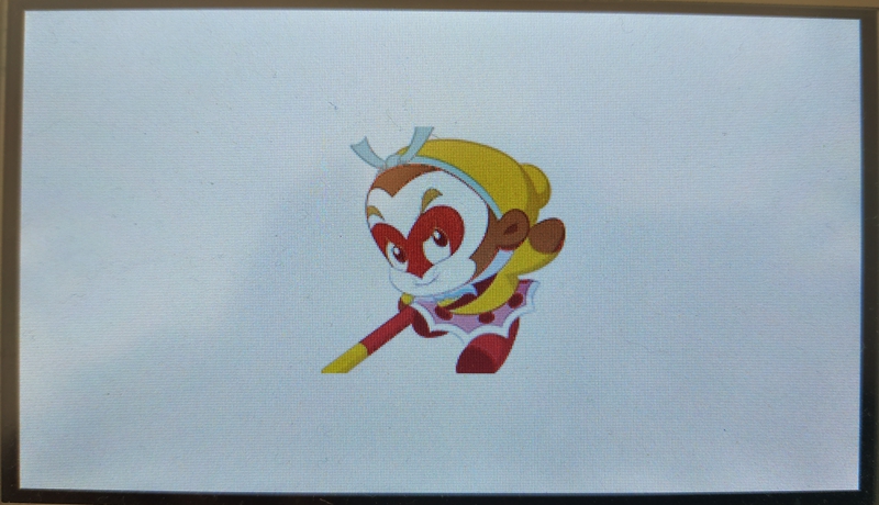
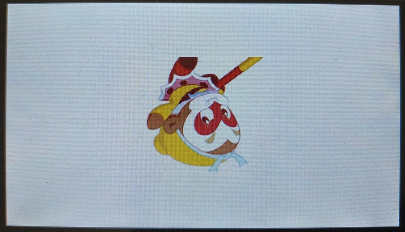
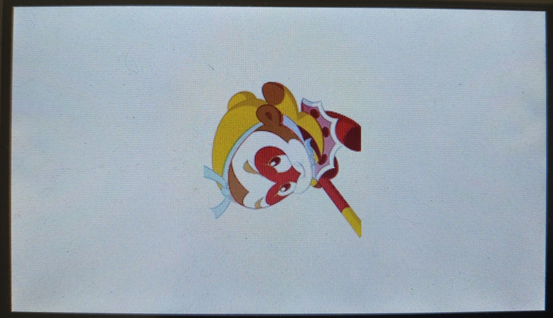
endmodule三、上板验证
总共4种模式,模式0、1、2、3 分别得到如下结果:

把这4副图也按MATLAB的样子拼到一块看看吧:
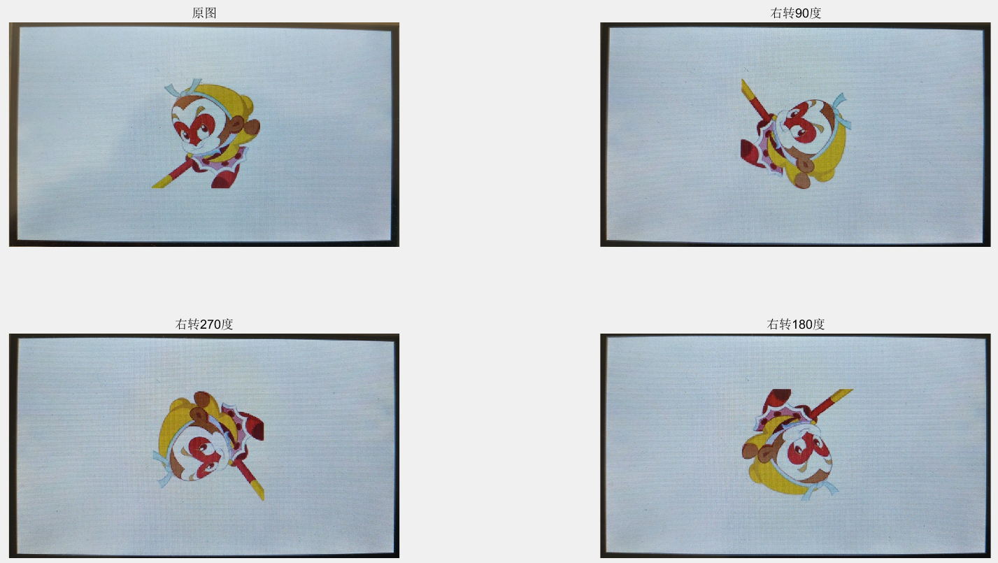
和上面的 MATLAB 实验结果对比,可以看到此次图像旋转实验成功。
视频演示如下所示:
后记
本博客整理的旋转算法仅支持90度周期的旋转,任意角度的旋转算法还待进一步研究。此外本次所选图片为正方形,如果是长方形图片,则必须在设计旋转算法的模块好好思考如何设计坐标和数值的对应关系。
参考资料:[1] OpenS Lee:FPGA开源工作室(公众号)

 浙公网安备 33010602011771号