

SPI
一,定义
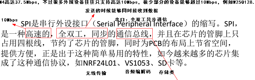
数据传输速度总体来说比I2C总线要快,速度可达到几Mbps。
缺点:没有指定的流控制,没有应答机制确认是否接收到数据。
二,单机与多机通信
1,单机通信

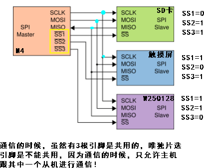
2,多机通信
三,通信细节与过程
在点对点的通信中, SPI接口不需要进行寻址操作,且为全双工通信,显得简单高效。在多个从器件的系统中,每个从器件需要独立的使能信号,
硬件上比I2C系统要稍微复杂一些。
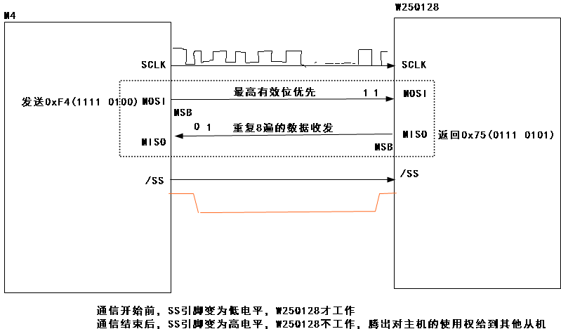
SPI接口在内部硬件实际上是两个简单的移位寄存器,传输的数据为8位,在主器件产生的从器件使能信号和移位脉冲下,按位传输,高位在前,低位在后。
如下图所示,在SCLK的上升沿上数据改变,同时一位数据被存入移位寄存器。
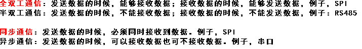
半双工通信追求的是距离,RS485 传输的距离可达1公里多
时序图

W25Q128_读ID

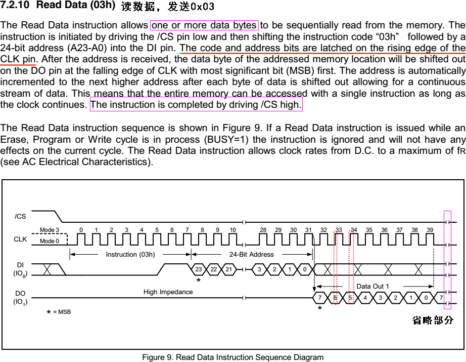
W25Q128_读数据.
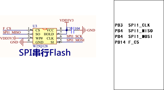
四,硬件原理图
五,工作模式
SPI有四种工作模式,各个工作模式的不同在于SCLK不同, 具体工作由CPOL,CPHA决定:
CPOL: (Clock Polarity),时钟极性
当CPOL为0时,时钟空闲时电平为低;
当CPOL为1时,时钟空闲时电平为高;
CPHA:(Clock Phase),时钟相位
当CPHA为0时,时钟周期的前一边缘采集数据,时钟周期的后一边缘输出数据;
当CPHA为1时,时钟周期的后一边缘采集数据,时钟周期的前一边缘输出数据;
CPOL和CPHA,分别都可以是0或时1,对应的四种组合就是:


#include <stdio.h>
#include "stm32f4xx.h"
#include "sys.h"
#include "string.h"

static GPIO_InitTypeDef   GPIO_InitStructure;

static NVIC_InitTypeDef   NVIC_InitStructure;

static USART_InitTypeDef  USART_InitStructure;

static SPI_InitTypeDef      SPI_InitStructure;

#define W25QXX_SS            PBout(14)

//重定义fputc函数
int fputc(int ch, FILE *f)
{
    USART_SendData(USART1,ch);
    while(USART_GetFlagStatus(USART1,USART_FLAG_TXE)==RESET);

    return ch;
}

void delay_us(uint32_t nus)
{
    uint32_t temp;
    SysTick->LOAD =SystemCoreClock/8/1000000*nus;     //时间加载
    SysTick->VAL  =0x00;                            //清空计数器
    SysTick->CTRL|=SysTick_CTRL_ENABLE_Msk ;         //使能滴答定时器开始倒数
    do
    {
        temp=SysTick->CTRL;
    }while((temp&0x01)&&!(temp&(1<<16)));            //等待时间到达
    SysTick->CTRL&=~SysTick_CTRL_ENABLE_Msk;         //关闭计数器
    SysTick->VAL =0X00;                               //清空计数器
}

void delay_ms(uint16_t nms)
{
    uint32_t temp;
    SysTick->LOAD=SystemCoreClock/8/1000*nms;        //时间加载(SysTick->LOAD为24bit)
    SysTick->VAL =0x00;                               //清空计数器
    SysTick->CTRL|=SysTick_CTRL_ENABLE_Msk ;        //能滴答定时器开始倒数
    do
    {
        temp=SysTick->CTRL;
    }while((temp&0x01)&&!(temp&(1<<16)));            //等待时间到达
    SysTick->CTRL&=~SysTick_CTRL_ENABLE_Msk;        //关闭计数器
    SysTick->VAL =0X00;                               //清空计数器
}

void USART1_Init(uint32_t baud)
{
    RCC_AHB1PeriphClockCmd(RCC_AHB1Periph_GPIOA,ENABLE);                             //使能GPIOA时钟
    RCC_APB2PeriphClockCmd(RCC_APB2Periph_USART1,ENABLE);                            //使能USART1时钟

    //串口1对应引脚复用映射
    GPIO_PinAFConfig(GPIOA,GPIO_PinSource9,GPIO_AF_USART1);                         //GPIOA9复用为USART1
    GPIO_PinAFConfig(GPIOA,GPIO_PinSource10,GPIO_AF_USART1);                         //GPIOA10复用为USART1

    //USART1端口配置
    GPIO_InitStructure.GPIO_Pin = GPIO_Pin_9 | GPIO_Pin_10;                         //GPIOA9与GPIOA10
    GPIO_InitStructure.GPIO_Mode = GPIO_Mode_AF;                                    //复用功能
    GPIO_InitStructure.GPIO_Speed = GPIO_Speed_50MHz;                                //速度50MHz
    GPIO_InitStructure.GPIO_OType = GPIO_OType_PP;                                     //推挽复用输出
    GPIO_InitStructure.GPIO_PuPd = GPIO_PuPd_UP;                                     //上拉
    GPIO_Init(GPIOA,&GPIO_InitStructure);                                             //初始化PA9,PA10

    //USART1 初始化设置
    USART_InitStructure.USART_BaudRate = baud;                                        //波特率设置
    USART_InitStructure.USART_WordLength = USART_WordLength_8b;                        //字长为8位数据格式
    USART_InitStructure.USART_StopBits = USART_StopBits_1;                            //一个停止位
    USART_InitStructure.USART_Parity = USART_Parity_No;                                //无奇偶校验位
    USART_InitStructure.USART_HardwareFlowControl = USART_HardwareFlowControl_None;    //无硬件数据流控制
    USART_InitStructure.USART_Mode = USART_Mode_Rx | USART_Mode_Tx;                    //收发模式
    USART_Init(USART1, &USART_InitStructure);                                         //初始化串口

    USART_Cmd(USART1, ENABLE);                                                      //使能串口1

    USART_ITConfig(USART1, USART_IT_RXNE, ENABLE);                                    //开启相关中断

    //Usart1 NVIC 配置
    NVIC_InitStructure.NVIC_IRQChannel = USART1_IRQn;                                //串口1中断通道
    NVIC_InitStructure.NVIC_IRQChannelPreemptionPriority=3;                            //抢占优先级3
    NVIC_InitStructure.NVIC_IRQChannelSubPriority =3;                                //子优先级3
    NVIC_InitStructure.NVIC_IRQChannelCmd = ENABLE;                                    //IRQ通道使能
    NVIC_Init(&NVIC_InitStructure);                                                    //根据指定的参数初始化VIC寄存器
}

void w25qxx_init(void)
{
    /*!< Enable the SPI clock ,使能SPI1硬件时钟*/
    RCC_APB2PeriphClockCmd(RCC_APB2Periph_SPI1, ENABLE);

    /*!< Enable GPIO clocks ,使能GPIOB的硬件时钟*/
    RCC_AHB1PeriphClockCmd(RCC_AHB1Periph_GPIOB, ENABLE);

    /*!< SPI pins configuration *************************************************/

    /*!< Connect SPI pins to AF5 */
    GPIO_PinAFConfig(GPIOB, GPIO_PinSource3, GPIO_AF_SPI1);
    GPIO_PinAFConfig(GPIOB, GPIO_PinSource4, GPIO_AF_SPI1);
    GPIO_PinAFConfig(GPIOB, GPIO_PinSource5, GPIO_AF_SPI1);

    GPIO_InitStructure.GPIO_Mode = GPIO_Mode_AF;
    GPIO_InitStructure.GPIO_Speed = GPIO_Speed_50MHz;
    GPIO_InitStructure.GPIO_OType = GPIO_OType_PP;
    GPIO_InitStructure.GPIO_PuPd  = GPIO_PuPd_DOWN;

    /*!< SPI SCK pin configuration */
    GPIO_InitStructure.GPIO_Pin = GPIO_Pin_3;
    GPIO_Init(GPIOB, &GPIO_InitStructure);

    /*!< SPI MOSI pin configuration */
    GPIO_InitStructure.GPIO_Pin =  GPIO_Pin_5;
    GPIO_Init(GPIOB, &GPIO_InitStructure);

    /*!< SPI MISO pin configuration */
    GPIO_InitStructure.GPIO_Pin =  GPIO_Pin_4;
    GPIO_Init(GPIOB, &GPIO_InitStructure);

    /*!< Configure sFLASH Card CS pin in output pushpull mode ,配置片选引脚PB14为输出模式*/
    GPIO_InitStructure.GPIO_Pin = GPIO_Pin_14;
    GPIO_InitStructure.GPIO_Mode = GPIO_Mode_OUT;
    GPIO_InitStructure.GPIO_OType = GPIO_OType_PP;
    GPIO_InitStructure.GPIO_Speed = GPIO_Speed_50MHz;
    GPIO_InitStructure.GPIO_PuPd = GPIO_PuPd_NOPULL;
    GPIO_Init(GPIOB, &GPIO_InitStructure);

    //由于M4芯片还没有真正配置好,先不让外部从机工作
    W25QXX_SS=1;

    /*!< SPI configuration ,SPI的配置*/
    SPI_InitStructure.SPI_Direction = SPI_Direction_2Lines_FullDuplex;        //设置SPI为全双工双线双向通信
    SPI_InitStructure.SPI_Mode = SPI_Mode_Master;                            //配置M4为主机角色
    SPI_InitStructure.SPI_DataSize = SPI_DataSize_8b;                        //SPI的发送和接收都是8bit
    SPI_InitStructure.SPI_CPOL = SPI_CPOL_High;                                //串行时钟线(SCLK)空闲的时候是高电平还是低电平,该电平的设置是跟外围设备密切关系的。
    SPI_InitStructure.SPI_CPHA = SPI_CPHA_2Edge;                            //串行时钟的第二跳变沿进行数据采样
    SPI_InitStructure.SPI_NSS = SPI_NSS_Soft;                                //片选引脚是由软件控制
    SPI_InitStructure.SPI_BaudRatePrescaler = SPI_BaudRatePrescaler_16;        //SPI通信时钟=84MHz/16=5.25MHz

    SPI_InitStructure.SPI_FirstBit = SPI_FirstBit_MSB;                        //最高有效位优先,根据外围设备的通信进行设定
    SPI_Init(SPI1, &SPI_InitStructure);

    /*!< Enable the sFLASH_SPI  ,使能SPI1*/
    SPI_Cmd(SPI1, ENABLE);

}

uint8_t SPI1_SendByte(uint8_t byte)
{
    /*!< Loop while DR register in not emplty ,等待发送缓冲区为空*/
    while (SPI_I2S_GetFlagStatus(SPI1, SPI_I2S_FLAG_TXE) == RESET);

    /*!< Send byte through the SPI1 peripheral,通过SPI1发送字节 */
    SPI_I2S_SendData(SPI1, byte);

    /*!< Wait to receive a byte ,等待接收字节*/
    while (SPI_I2S_GetFlagStatus(SPI1, SPI_I2S_FLAG_RXNE) == RESET);

    /*!< Return the byte read from the SPI bus,成功接收从机的字节并返回 */
    return SPI_I2S_ReceiveData(SPI1);
}


uint16_t w25qxx_read_id(void)
{
    uint16_t id=0;

    //片选引脚拉低
    W25QXX_SS=0;


    //发送0x90
    SPI1_SendByte(0x90);

    //发送24bit地址,全都是0
    SPI1_SendByte(0x00);
    SPI1_SendByte(0x00);
    SPI1_SendByte(0x00);

    //读取厂商ID,传递任意的参数
    id=SPI1_SendByte(0xFF)<<8;

    //读取设备ID,传递任意的参数
    id|=SPI1_SendByte(0xFF);

    //片选引脚拉高
    W25QXX_SS=1;

    return id;

}

void w25qxx_read_data(uint32_t addr,uint8_t *pbuf,uint32_t len)
{
    //片选引脚拉低
    W25QXX_SS=0;

    //发送0x03
    SPI1_SendByte(0x03);

    //发送24bit地址
    SPI1_SendByte((addr>>16)&0xFF);
    SPI1_SendByte((addr>>8)&0xFF);
    SPI1_SendByte( addr&0xFF);

    //读取数据
    while(len--)
        *pbuf++ = SPI1_SendByte(0xFF);

    //片选引脚拉高
    W25QXX_SS=1;
}

//解除写保护
void w25qxx_write_enable(void)
{
    //片选引脚拉低
    W25QXX_SS=0;

    //发送0x06
    SPI1_SendByte(0x06);

    //片选引脚拉高
    W25QXX_SS=1;

}

//写保护
void w25qxx_write_disable(void)
{
    //片选引脚拉低
    W25QXX_SS=0;

    //发送0x04
    SPI1_SendByte(0x04);

    //片选引脚拉高
    W25QXX_SS=1;


}

uint8_t w25qxx_read_status1(void)
{
    uint8_t status;

    //片选引脚拉低
    W25QXX_SS=0;

    //发送0x05
    SPI1_SendByte(0x05);

    //读取状态寄存器1的值
    status = SPI1_SendByte(0xFF);

    //片选引脚拉高
    W25QXX_SS=1;


    return status;

}

void w25qxx_erase_sector(uint32_t addr)
{
    uint8_t sta=0;
    //解除写保护
    w25qxx_write_enable();

    //延时1ms,让W25Q128识别到CS引脚的变化
    delay_ms(1);

    //片选引脚拉低
    W25QXX_SS=0;

    //发送0x20
    SPI1_SendByte(0x20);

    //发送24bit地址
    SPI1_SendByte((addr>>16)&0xFF);
    SPI1_SendByte((addr>>8)&0xFF);
    SPI1_SendByte( addr&0xFF);

    //片选引脚拉高
    W25QXX_SS=1;

    //去判断当前是否已经擦除成功
    while(1)
    {
        sta = w25qxx_read_status1();

        if((sta & 0x01)==0)
            break;

        delay_ms(1);
    }

    //开启写保护
    w25qxx_write_disable();
}


void w25qxx_write_data(uint32_t addr,uint8_t *pbuf,uint32_t len)
{
    uint8_t sta=0;
    //解除写保护
    w25qxx_write_enable();

    //延时1ms,让W25Q128识别到CS引脚的变化
    delay_ms(1);

    //片选引脚拉低
    W25QXX_SS=0;

    //发送0x02
    SPI1_SendByte(0x02);

    //发送24bit地址
    SPI1_SendByte((addr>>16)&0xFF);
    SPI1_SendByte((addr>>8)&0xFF);
    SPI1_SendByte( addr&0xFF);

    //发送数据
    while(len--)
        SPI1_SendByte(*pbuf++);

    //片选引脚拉高
    W25QXX_SS=1;

    //去判断当前是否已经写入成功
    while(1)
    {
        sta = w25qxx_read_status1();

        if((sta & 0x01)==0)
            break;

        delay_ms(1);
    }

    //开启写保护
    w25qxx_write_disable();
}


int main(void)
{
    uint16_t w25qxx_id=0;
    uint8_t buf_wr[64]={0};
    uint8_t buf_rd[64]={0};
    uint32_t i=0;

    //系统定时器初始化,时钟源来自HCLK,且进行8分频,
    //系统定时器时钟频率=168MHz/8=21MHz
    SysTick_CLKSourceConfig(SysTick_CLKSource_HCLK_Div8);

    //设置中断优先级分组2
    NVIC_PriorityGroupConfig(NVIC_PriorityGroup_2);

    //串口1,波特率115200bps,开启接收中断
    USART1_Init(115200);

    //w25qxx初始化
    w25qxx_init();

    printf("This is spi flash test\r\n");

    w25qxx_id=w25qxx_read_id();

    printf("w25qxx id=%X\r\n",w25qxx_id);


    //进行扇区擦除
    printf("w25qxx erase from 0\r\n");
    w25qxx_erase_sector(0);


    //写入数据
    printf("w25qxx write at 0,data all is 1\r\n");
    memset(buf_wr,'1',sizeof buf_wr);
    w25qxx_write_data(0,buf_wr,64);

    //读取数据
    printf("w25qxx read at 0\r\n");
    memset(buf_rd,0,sizeof buf_rd);
    w25qxx_read_data(0,buf_rd,64);

    for(i=0; i<64; i++)
    {
        printf("%c ",buf_rd[i]);
    }

    while(1)
    {


    }

}
#ifndef __SYS_H__
#define __SYS_H__

//位带操作,实现51类似的GPIO控制功能
//IO口操作宏定义
#define BITBAND(addr, bitnum) ((addr & 0xF0000000)+0x2000000+((addr &0xFFFFF)<<5)+(bitnum<<2))
#define MEM_ADDR(addr)  *((volatile unsigned long  *)(addr))
#define BIT_ADDR(addr, bitnum)   MEM_ADDR(BITBAND(addr, bitnum))

//IO口地址映射
#define GPIOA_ODR_Addr    (GPIOA_BASE+20) //0x40020014
#define GPIOB_ODR_Addr    (GPIOB_BASE+20) //0x40020414
#define GPIOC_ODR_Addr    (GPIOC_BASE+20) //0x40020814
#define GPIOD_ODR_Addr    (GPIOD_BASE+20) //0x40020C14
#define GPIOE_ODR_Addr    (GPIOE_BASE+20) //0x40021014
#define GPIOF_ODR_Addr    (GPIOF_BASE+20) //0x40021414
#define GPIOG_ODR_Addr    (GPIOG_BASE+20) //0x40021814
#define GPIOH_ODR_Addr    (GPIOH_BASE+20) //0x40021C14
#define GPIOI_ODR_Addr    (GPIOI_BASE+20) //0x40022014

#define GPIOA_IDR_Addr    (GPIOA_BASE+16) //0x40020010
#define GPIOB_IDR_Addr    (GPIOB_BASE+16) //0x40020410
#define GPIOC_IDR_Addr    (GPIOC_BASE+16) //0x40020810
#define GPIOD_IDR_Addr    (GPIOD_BASE+16) //0x40020C10
#define GPIOE_IDR_Addr    (GPIOE_BASE+16) //0x40021010
#define GPIOF_IDR_Addr    (GPIOF_BASE+16) //0x40021410
#define GPIOG_IDR_Addr    (GPIOG_BASE+16) //0x40021810
#define GPIOH_IDR_Addr    (GPIOH_BASE+16) //0x40021C10
#define GPIOI_IDR_Addr    (GPIOI_BASE+16) //0x40022010

//IO口操作,只对单一的IO口!
//确保n的值小于16!
#define PAout(n)   BIT_ADDR(GPIOA_ODR_Addr,n)  //输出
#define PAin(n)    BIT_ADDR(GPIOA_IDR_Addr,n)  //输入

#define PBout(n)   BIT_ADDR(GPIOB_ODR_Addr,n)  //输出
#define PBin(n)    BIT_ADDR(GPIOB_IDR_Addr,n)  //输入

#define PCout(n)   BIT_ADDR(GPIOC_ODR_Addr,n)  //输出
#define PCin(n)    BIT_ADDR(GPIOC_IDR_Addr,n)  //输入

#define PDout(n)   BIT_ADDR(GPIOD_ODR_Addr,n)  //输出
#define PDin(n)    BIT_ADDR(GPIOD_IDR_Addr,n)  //输入

#define PEout(n)   BIT_ADDR(GPIOE_ODR_Addr,n)  //输出
#define PEin(n)    BIT_ADDR(GPIOE_IDR_Addr,n)  //输入

#define PFout(n)   BIT_ADDR(GPIOF_ODR_Addr,n)  //输出
#define PFin(n)    BIT_ADDR(GPIOF_IDR_Addr,n)  //输入

#define PGout(n)   BIT_ADDR(GPIOG_ODR_Addr,n)  //输出
#define PGin(n)    BIT_ADDR(GPIOG_IDR_Addr,n)  //输入

#define PHout(n)   BIT_ADDR(GPIOH_ODR_Addr,n)  //输出
#define PHin(n)    BIT_ADDR(GPIOH_IDR_Addr,n)  //输入

#define PIout(n)   BIT_ADDR(GPIOI_ODR_Addr,n)  //输出
#define PIin(n)    BIT_ADDR(GPIOI_IDR_Addr,n)  //输入

#endif
#include <stdio.h>
#include "stm32f4xx.h"
#include "sys.h"
#include "string.h"

static GPIO_InitTypeDef   GPIO_InitStructure;

static NVIC_InitTypeDef   NVIC_InitStructure;

static USART_InitTypeDef  USART_InitStructure;

static SPI_InitTypeDef      SPI_InitStructure;

#define W25QXX_SS            PBout(14)
#define W25QXX_SCLK            PBout(3)
#define W25QXX_MOSI            PBout(5)
#define W25QXX_MISO            PBin(4)

//重定义fputc函数
int fputc(int ch, FILE *f)
{
    USART_SendData(USART1,ch);
    while(USART_GetFlagStatus(USART1,USART_FLAG_TXE)==RESET);

    return ch;
}

void delay_us(uint32_t nus)
{
    uint32_t temp;
    SysTick->LOAD =SystemCoreClock/8/1000000*nus;     //时间加载
    SysTick->VAL  =0x00;                            //清空计数器
    SysTick->CTRL|=SysTick_CTRL_ENABLE_Msk ;         //使能滴答定时器开始倒数
    do
    {
        temp=SysTick->CTRL;
    }while((temp&0x01)&&!(temp&(1<<16)));            //等待时间到达
    SysTick->CTRL&=~SysTick_CTRL_ENABLE_Msk;         //关闭计数器
    SysTick->VAL =0X00;                               //清空计数器
}

void delay_ms(uint16_t nms)
{
    uint32_t temp;
    SysTick->LOAD=SystemCoreClock/8/1000*nms;        //时间加载(SysTick->LOAD为24bit)
    SysTick->VAL =0x00;                               //清空计数器
    SysTick->CTRL|=SysTick_CTRL_ENABLE_Msk ;        //能滴答定时器开始倒数
    do
    {
        temp=SysTick->CTRL;
    }while((temp&0x01)&&!(temp&(1<<16)));            //等待时间到达
    SysTick->CTRL&=~SysTick_CTRL_ENABLE_Msk;        //关闭计数器
    SysTick->VAL =0X00;                               //清空计数器
}

void USART1_Init(uint32_t baud)
{
    RCC_AHB1PeriphClockCmd(RCC_AHB1Periph_GPIOA,ENABLE);                             //使能GPIOA时钟
    RCC_APB2PeriphClockCmd(RCC_APB2Periph_USART1,ENABLE);                            //使能USART1时钟

    //串口1对应引脚复用映射
    GPIO_PinAFConfig(GPIOA,GPIO_PinSource9,GPIO_AF_USART1);                         //GPIOA9复用为USART1
    GPIO_PinAFConfig(GPIOA,GPIO_PinSource10,GPIO_AF_USART1);                         //GPIOA10复用为USART1

    //USART1端口配置
    GPIO_InitStructure.GPIO_Pin = GPIO_Pin_9 | GPIO_Pin_10;                         //GPIOA9与GPIOA10
    GPIO_InitStructure.GPIO_Mode = GPIO_Mode_AF;                                    //复用功能
    GPIO_InitStructure.GPIO_Speed = GPIO_Speed_50MHz;                                //速度50MHz
    GPIO_InitStructure.GPIO_OType = GPIO_OType_PP;                                     //推挽复用输出
    GPIO_InitStructure.GPIO_PuPd = GPIO_PuPd_UP;                                     //上拉
    GPIO_Init(GPIOA,&GPIO_InitStructure);                                             //初始化PA9,PA10

    //USART1 初始化设置
    USART_InitStructure.USART_BaudRate = baud;                                        //波特率设置
    USART_InitStructure.USART_WordLength = USART_WordLength_8b;                        //字长为8位数据格式
    USART_InitStructure.USART_StopBits = USART_StopBits_1;                            //一个停止位
    USART_InitStructure.USART_Parity = USART_Parity_No;                                //无奇偶校验位
    USART_InitStructure.USART_HardwareFlowControl = USART_HardwareFlowControl_None;    //无硬件数据流控制
    USART_InitStructure.USART_Mode = USART_Mode_Rx | USART_Mode_Tx;                    //收发模式
    USART_Init(USART1, &USART_InitStructure);                                         //初始化串口

    USART_Cmd(USART1, ENABLE);                                                      //使能串口1

    USART_ITConfig(USART1, USART_IT_RXNE, ENABLE);                                    //开启相关中断

    //Usart1 NVIC 配置
    NVIC_InitStructure.NVIC_IRQChannel = USART1_IRQn;                                //串口1中断通道
    NVIC_InitStructure.NVIC_IRQChannelPreemptionPriority=3;                            //抢占优先级3
    NVIC_InitStructure.NVIC_IRQChannelSubPriority =3;                                //子优先级3
    NVIC_InitStructure.NVIC_IRQChannelCmd = ENABLE;                                    //IRQ通道使能
    NVIC_Init(&NVIC_InitStructure);                                                    //根据指定的参数初始化VIC寄存器
}

void w25qxx_init(void)
{

    /*!< Enable GPIO clocks ,使能GPIOB的硬件时钟*/
    RCC_AHB1PeriphClockCmd(RCC_AHB1Periph_GPIOB, ENABLE);


    /* 配置片选引脚PB3 PB5 PB14为输出模式*/
    GPIO_InitStructure.GPIO_Pin = GPIO_Pin_3|GPIO_Pin_5|GPIO_Pin_14;
    GPIO_InitStructure.GPIO_Mode = GPIO_Mode_OUT;
    GPIO_InitStructure.GPIO_OType = GPIO_OType_PP;
    GPIO_InitStructure.GPIO_Speed = GPIO_Speed_50MHz;
    GPIO_InitStructure.GPIO_PuPd = GPIO_PuPd_NOPULL;
    GPIO_Init(GPIOB, &GPIO_InitStructure);

    /* 配置片选引脚PB4为输入模式*/
    GPIO_InitStructure.GPIO_Pin = GPIO_Pin_4;
    GPIO_InitStructure.GPIO_Mode = GPIO_Mode_IN;
    GPIO_InitStructure.GPIO_Speed = GPIO_Speed_50MHz;
    GPIO_InitStructure.GPIO_PuPd = GPIO_PuPd_NOPULL;
    GPIO_Init(GPIOB, &GPIO_InitStructure);

    //由于M4芯片还没有真正配置好,先不让外部从机工作
    W25QXX_SS=1;
}

uint8_t SPI1_SendByte(uint8_t byte)
{
    uint32_t i=0;
    uint8_t d=0;

    for(i=0; i<8; i++)
    {
        //MSB,最高有效位发送数据
        if(byte & (1<<(7-i)))
            W25QXX_MOSI =1;
        else
            W25QXX_MOSI =0;

        //设置SCLK引脚为低电平
        W25QXX_SCLK=0;
        delay_us(2);


        //由于是同步事件
        if(W25QXX_MISO)
            d|=1<<(7-i);


        //设置SCLK引脚为高电平
        W25QXX_SCLK=1;
        delay_us(2);


    }

    return d;
}


uint16_t w25qxx_read_id(void)
{
    uint16_t id=0;

    //片选引脚拉低
    W25QXX_SS=0;


    //发送0x90
    SPI1_SendByte(0x90);

    //发送24bit地址,全都是0
    SPI1_SendByte(0x00);
    SPI1_SendByte(0x00);
    SPI1_SendByte(0x00);

    //读取厂商ID,传递任意的参数
    id=SPI1_SendByte(0xFF)<<8;

    //读取设备ID,传递任意的参数
    id|=SPI1_SendByte(0xFF);

    //片选引脚拉高
    W25QXX_SS=1;

    return id;

}

void w25qxx_read_data(uint32_t addr,uint8_t *pbuf,uint32_t len)
{
    //片选引脚拉低
    W25QXX_SS=0;

    //发送0x03
    SPI1_SendByte(0x03);

    //发送24bit地址
    SPI1_SendByte((addr>>16)&0xFF);
    SPI1_SendByte((addr>>8)&0xFF);
    SPI1_SendByte( addr&0xFF);

    //读取数据
    while(len--)
        *pbuf++ = SPI1_SendByte(0xFF);

    //片选引脚拉高
    W25QXX_SS=1;
}

//解除写保护
void w25qxx_write_enable(void)
{
    //片选引脚拉低
    W25QXX_SS=0;

    //发送0x06
    SPI1_SendByte(0x06);

    //片选引脚拉高
    W25QXX_SS=1;

}

//写保护
void w25qxx_write_disable(void)
{
    //片选引脚拉低
    W25QXX_SS=0;

    //发送0x04
    SPI1_SendByte(0x04);

    //片选引脚拉高
    W25QXX_SS=1;


}

uint8_t w25qxx_read_status1(void)
{
    uint8_t status;

    //片选引脚拉低
    W25QXX_SS=0;

    //发送0x05
    SPI1_SendByte(0x05);

    //读取状态寄存器1的值
    status = SPI1_SendByte(0xFF);

    //片选引脚拉高
    W25QXX_SS=1;


    return status;

}

void w25qxx_erase_sector(uint32_t addr)
{
    uint8_t sta=0;
    //解除写保护
    w25qxx_write_enable();

    //延时1ms,让W25Q128识别到CS引脚的变化
    delay_ms(1);

    //片选引脚拉低
    W25QXX_SS=0;

    //发送0x20
    SPI1_SendByte(0x20);

    //发送24bit地址
    SPI1_SendByte((addr>>16)&0xFF);
    SPI1_SendByte((addr>>8)&0xFF);
    SPI1_SendByte( addr&0xFF);

    //片选引脚拉高
    W25QXX_SS=1;

    //去判断当前是否已经擦除成功
    while(1)
    {
        sta = w25qxx_read_status1();

        if((sta & 0x01)==0)
            break;

        delay_ms(1);
    }

    //开启写保护
    w25qxx_write_disable();
}


void w25qxx_write_data(uint32_t addr,uint8_t *pbuf,uint32_t len)
{
    uint8_t sta=0;
    //解除写保护
    w25qxx_write_enable();

    //延时1ms,让W25Q128识别到CS引脚的变化
    delay_ms(1);

    //片选引脚拉低
    W25QXX_SS=0;

    //发送0x02
    SPI1_SendByte(0x02);

    //发送24bit地址
    SPI1_SendByte((addr>>16)&0xFF);
    SPI1_SendByte((addr>>8)&0xFF);
    SPI1_SendByte( addr&0xFF);

    //发送数据
    while(len--)
        SPI1_SendByte(*pbuf++);

    //片选引脚拉高
    W25QXX_SS=1;

    //去判断当前是否已经写入成功
    while(1)
    {
        sta = w25qxx_read_status1();

        if((sta & 0x01)==0)
            break;

        delay_ms(1);
    }

    //开启写保护
    w25qxx_write_disable();
}


int main(void)
{
    uint16_t w25qxx_id=0;
    uint8_t buf_wr[64]={0};
    uint8_t buf_rd[64]={0};
    uint32_t i=0;

    //系统定时器初始化,时钟源来自HCLK,且进行8分频,
    //系统定时器时钟频率=168MHz/8=21MHz
    SysTick_CLKSourceConfig(SysTick_CLKSource_HCLK_Div8);

    //设置中断优先级分组2
    NVIC_PriorityGroupConfig(NVIC_PriorityGroup_2);

    //串口1,波特率115200bps,开启接收中断
    USART1_Init(115200);

    //w25qxx初始化
    w25qxx_init();

    printf("This is spi flash test\r\n");

    w25qxx_id=w25qxx_read_id();

    printf("w25qxx id=%X\r\n",w25qxx_id);


    //进行扇区擦除
    printf("w25qxx erase from 0\r\n");
    w25qxx_erase_sector(0);


    //写入数据
    printf("w25qxx write at 0,data all is 1\r\n");
    memset(buf_wr,'1',sizeof buf_wr);
    w25qxx_write_data(0,buf_wr,64);

    //读取数据
    printf("w25qxx read at 0\r\n");
    memset(buf_rd,0,sizeof buf_rd);
    w25qxx_read_data(0,buf_rd,64);

    for(i=0; i<64; i++)
    {
        printf("%c ",buf_rd[i]);
    }

    while(1)
    {


    }

}
练习:
通过ubuntu编写一个串口程序,通过该程序下载该文件到M4的SPI FLASH,实现移动小U盘,详细要求如下:
1)终端输入“down 文件名”,下载过程当中要显示当前的进度
2)终端输入“up 文件名”,上传过程当中要显示当前的进度
实现RFID代码的移植,实现卡的读写!
思考题1:读取数据一次性最多能够读取多少个字节?
思考题2:在进行读取数据的时候,SPI1_SendByte函数的参数能不能任意值?

 浙公网安备 33010602011771号