Segment Descriptors
A segment descriptor is a data structure in a GDT or LDT that provides the processor with the size and location of a segment, as well as access control and status information. Segment descriptors are typically created by
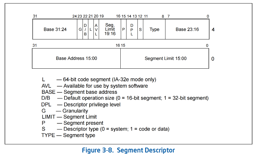
compilers, linkers, loaders, or the operating system or executive, but not application programs. Figure 3-8 illustrates the general descriptor format for all types of segment descriptors.
The flags and fields in a segment descriptor are as follows:
Segment limit field(20 bits)
Specifies the size of the segment. The processor puts together the two segment limit fields to form
a 20-bit value. The processor interprets the segment limit in one of two ways, depending on the
setting of the G (granularity) flag:
• If the granularity flag is clear, the segment size can range from 1 byte to 1 MByte, in byte incre�
ments.
• If the granularity flag is set, the segment size can range from 4 KBytes to 4 GBytes, in 4-KByte
increments.
The processor uses the segment limit in two different ways, depending on whether the segment is
an expand-up or an expand-down segment. See Section 3.4.5.1, “Code- and Data-Segment
Descriptor Types”, for more information about segment types. For expand-up segments, the offset
in a logical address can range from 0 to the segment limit. Offsets greater than the segment limit
generate general-protection exceptions (#GP, for all segments other than SS) or stack-fault excep�
tions (#SS for the SS segment). For expand-down segments, the segment limit has the reverse
function; the offset can range from the segment limit plus 1 to FFFFFFFFH or FFFFH, depending on
the setting of the B flag. Offsets less than or equal to the segment limit generate general-protection
exceptions or stack-fault exceptions. Decreasing the value in the segment limit field for an expand�
down segment allocates new memory at the bottom of the segment's address space, rather than at
the top. IA-32 architecture stacks always grow downwards, making this mechanism convenient for
expandable stacks.
Base address fields(32 bits)
Defines the location of byte 0 of the segment within the 4-GByte linear address space. The
processor puts together the three base address fields to form a single 32-bit value. Segment base
addresses should be aligned to 16-byte boundaries. Although 16-byte alignment is not required,
this alignment allows programs to maximize performance by aligning code and data on 16-byte
boundaries.
Type field (4 bits)
Indicates the segment or gate type and specifies the kinds of access that can be made to the
segment and the direction of growth. The interpretation of this field depends on whether the
descriptor type flag specifies an application (code or data) descriptor or a system descriptor. The
encoding of the type field is different for code, data, and system descriptors (see Figure 5-1). See
Section 3.4.5.1, “Code- and Data-Segment Descriptor Types”, for a description of how this field is
used to specify code and data-segment types.
S (descriptor type) flag
Specifies whether the segment descriptor is for a system segment (S flag is clear) or a code or data
segment (S flag is set).
DPL (descriptor privilege level) field
Specifies the privilege level of the segment. The privilege level can range from 0 to 3, with 0 being
the most privileged level. The DPL is used to control access to the segment. See Section 5.5, “Priv�
ilege Levels”, for a description of the relationship of the DPL to the CPL of the executing code
segment and the RPL of a segment selector.
P (segment-present) flag
Indicates whether the segment is present in memory (set) or not present (clear). If this flag is clear,
the processor generates a segment-not-present exception (#NP) when a segment selector that
points to the segment descriptor is loaded into a segment register. Memory management software
can use this flag to control which segments are actually loaded into physical memory at a given
time. It offers a control in addition to paging for managing virtual memory.
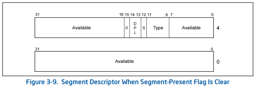
Figure 3-9 shows the format of a segment descriptor when the segment-present flag is clear. When
this flag is clear, the operating system or executive is free to use the locations marked “Available” to
store its own data, such as information regarding the whereabouts of the missing segment.
D/B (default operation size/default stack pointer size and/or upper bound) flag
Performs different functions depending on whether the segment descriptor is an executable code
segment, an expand-down data segment, or a stack segment. (This flag should always be set to 1
for 32-bit code and data segments and to 0 for 16-bit code and data segments.)
•
Executable code segment. The flag is called the D flag and it indicates the default length for
effective addresses and operands referenced by instructions in the segment. If the flag is set,
32-bit addresses and 32-bit or 8-bit operands are assumed; if it is clear, 16-bit addresses and
16-bit or 8-bit operands are assumed.
The instruction prefix 66H can be used to select an operand size other than the default, and the
prefix 67H can be used select an address size other than the default.
•
Stack segment (data segment pointed to by the SS register). The flag is called the B (big)
flag and it specifies the size of the stack pointer used for implicit stack operations (such as
pushes, pops, and calls). If the flag is set, a 32-bit stack pointer is used, which is stored in the
32-bit ESP register; if the flag is clear, a 16-bit stack pointer is used, which is stored in the 16-
bit SP register. If the stack segment is set up to be an expand-down data segment (described in
the next paragraph), the B flag also specifies the upper bound of the stack segment.
•
Expand-down data segment. The flag is called the B flag and it specifies the upper bound of
the segment. If the flag is set, the upper bound is FFFFFFFFH (4 GBytes); if the flag is clear, the
upper bound is FFFFH (64 KBytes).


 浙公网安备 33010602011771号