Vision Algorithms for Mobile Robotics学习笔记
Introduction
- The definition of Visual
Visual Odometry(VO) is the process of incrementally estimating the pose of the vehicle by examing the changes that motion induces on the images of its onboard cameras.
- The most important differences between VO, VSLAM and SFM:
- The relationship :
![]()
Fig. 1 The relation among VO, VSLAM and SFM
- For the detail:
- VO and VSLAM are the particular cases of SFM
- VSLAM involves the mapping, so it should garantees the global consistency. In fact, VSLAM = VO + loop detection & closure
- VO focuses on estimating the 6DoF motion of the camera **sequencially**(as a new frame arrives) and in **real time**
- The assumption for VO:
- Sufficient illumination in the enviroment
- Dominance of static scene over moing objects
- Enough texture to allow apparent motion to be extracted
- Sufficient scene overlap between consecutive frame
- The building blocks include:
![]()
Fig. 2 VO Flow Chart
- A blur bircle is:
![]()
Fig. 3 Blur bircle plot
The cause of "Blur Circle" is come from the image plan is different from the focal plan: the location of the ray pass through the center of lens defer from the location of the ray pass through others. The radius of Blur Circle is: $R = \frac{L\delta}{2e}$
- **Thin lens equation and pinhole approximation:**
![]() Fig. 4 This lens plot
Fig. 4 This lens plot
The thin lens equation assume the les is thin enough to overlook. And the equation is:
$\frac{1}{f} = \frac{1}{z} + \frac{1}{e}$
![]() Fig. 5 The pin-hole approximation
Fig. 5 The pin-hole approximation
The pin-hole approximation assume the distance from the obejct(to the camera)$z$ is much lager than focus length$f$, which is $z >> f$. We can derive from the previous equation that:
$\frac{1}{f} = \frac{1}{z} - \frac{1}{e}$
$\frac{1}{f} \approx \frac{1}{e}$, $f \approx e$
$\frac{h^{'}}{h} = \frac{f}{z}$
which develop the perspective vision: the dependence of the image of an object on its depth($z$)
- **Vanishing points and lines define:**
For the perspective projection, the image preserve the straight line but loss the information of length and angles which induce the parallel lines or planes will intersect to a point or line. These points or lines be called of Vanishing points or Vanishing lines.
- **Prove of parallel lines intersect at vanishing points:**
First we can define the very far points on two parallel lines:
$P_0 = \left[ \begin{array}{c}X_0 \\Y_0 \\Z_0 \end{array} \right] + s\left[ \begin{array}{c}l \\m\\n \end{array} \right]$
$P_1 = \left[ \begin{array}{c}X_1 \\Y_1 \\Z_1 \end{array} \right] + s\left[ \begin{array}{c}l \\m\\n \end{array} \right]$
When $s$ become infinite, the points in the image become:
$x_{p_1} = x_{p_2} = lim_{s \to \infty} f\frac{X_i + sl}{Z_i+sn} = f\frac{f}{n}$
$y_{p_1} = y_{p_2} = lim_{s \to \infty} f\frac{Y_i + sm}{Z_i+sn} = f\frac{m}{n}$
- **Build an Ames room:**
![]() Fig. 6 Ames room
Fig. 6 Ames room
- **The relation between the FOV and $f$ :**
$tan\frac{\theta}{2} = \frac{W}{2f}$ or $f = \frac{W}{2} [tan\frac{\theta}{2}]^{-1}$
- **Perspective projection equation, including lens distortion and word to camera projection:**
$\widetilde{p} = \left[ \begin{array}{c}\tilde{u} \\\tilde{v} \\\tilde{w} \end{array} \right] = \lambda\left[ \begin{array}{c}u\\v\\1 \end{array} \right] = K[R\,|\,T]\left[ \begin{array}{c} X_w\\Y_w\\Z_w\\1\end{array} \right]$
where $\lambda = Z_c$
For the radial distortion:
$\left[ \begin{array}{c}u_d \\ v_d \end{array} \right] = (1+k_{1} r^{2}) \left[ \begin{array}{c}u-u_0 \\ v - v_0\end{array} \right] + \left[ \begin{array}{c}u_0\\ v_0 \end{array} \right]$
where $r^2 = (u-u_0)^2 + (v-v_0)^2$
- **Excercise 1:**
- Determine the Intrinsic Parameter Matrix (K) of a digital camera with image size 640 x 480 pixels and a horizontal field of view of $90 ^{o}$
- Assume that the principal point is the center of the diagonals
- Also, assume that we have square pixels
- What is the vertical field of view?
<center>
![]()
Fig. 6 FOV and focus length
$tan\frac{\theta}{2} = \frac{W}{2f}$ or $f = \frac{W}{2}[tan\frac{\theta}{2}]^{-1}$
$f = \frac{640}{2tan\frac{\theta}{2}} = 320\, pixels$
$\theta_v = 2tan^{-1}\frac{H}{2f} = 2tan^{-1}\frac{480}{2\times320} \approx 73.74^{o}$
- General PnP problem and the behavior of its solutions:
![]()
Fig. 7 PnP problems
- **P3P algorithm:**
![]() Fig. 8 P3P algorithm
Fig. 8 P3P algorithm
From Carnot's Theorem:
$s_{1}^{2} = L_{B}^{2} + L_{C}^{2} - 2L_BL_C\theta_{BC}$
$s_{2}^{2} = L_{A}^{2} + L_{C}^{2} - 2L_AL_C\theta_{AC}$
$s_{3}^{2} = L_{A}^{2} + L_{B}^{2} - 2L_AL_B\theta_{AB}$
- **DLT and minimum number of point correspondences it requires:**
- From general 3D objects:
$\left[ \begin{array}{ccc}P_i^T & 0^T & -u_iP_i^T\\ 0^T & P_i^T &-v_iP_i^T \end{array}\right]\left[ \begin{array}{c} m_1 \\ m_2 \\ m_3\end{array}\right] = \left[ \begin{array}{c}0 \\ 0 \end{array}\right]$
$Q M = 0$
$Q \in R^{2n \times 12}$ should have rank 11, thus $5+\frac{1}{2} \approx 6$ points are needed.
$[U,S,V]=svd(Q)$,$M = V(:,12)$,$[K,R,T] = QR(M)$
- From Plannar grids:
$\left[ \begin{array}{ccc}P_i^T & 0^T & -u_iP_i^T\\ 0^T & P_i^T &-v_iP_i^T \end{array}\right]\left[ \begin{array}{c} h_1 \\ h_2 \\ h_3\end{array}\right] = \left[ \begin{array}{c}0 \\ 0 \end{array}\right]$
$Q H = 0$
$Q \in R^{2n \times 9}$ should have rank 8, thus $4$ points are needed.
$[U,S,V]=svd(Q)$,$M = V(:,9)$
- **Central and non central omnidirectional cameras:**
- **The mirrors ensure central projection:**


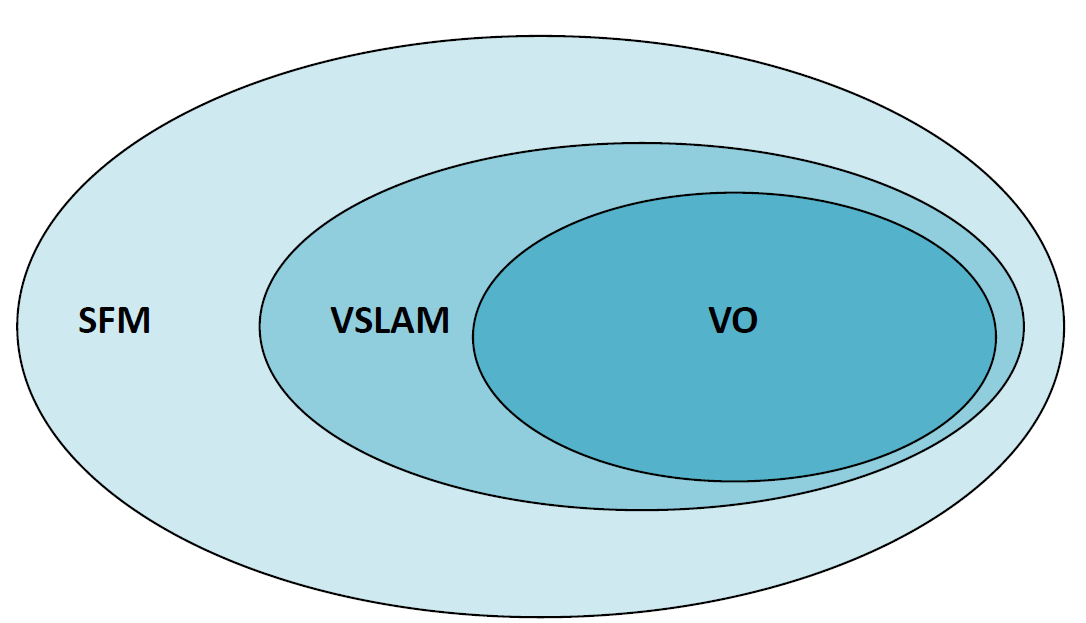
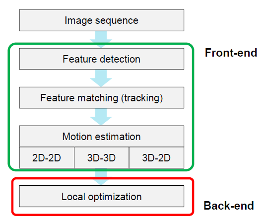
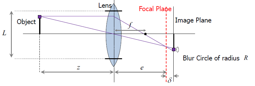
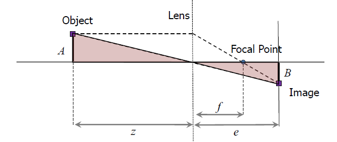 Fig. 4 This lens plot
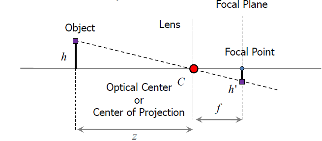 Fig. 5 The pin-hole approximation
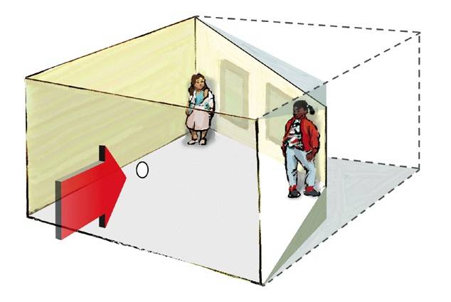 Fig. 6 Ames room
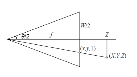 Fig. 6 FOV and focus length
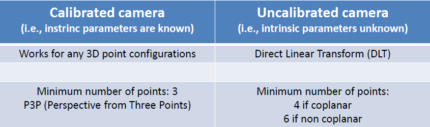 Fig. 7 PnP problems
- **P3P algorithm:**
Fig. 7 PnP problems
- **P3P algorithm:**
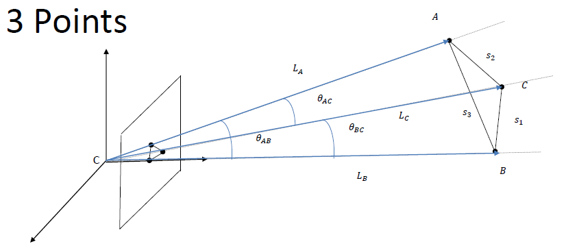 Fig. 8 P3P algorithm

 浙公网安备 33010602011771号