


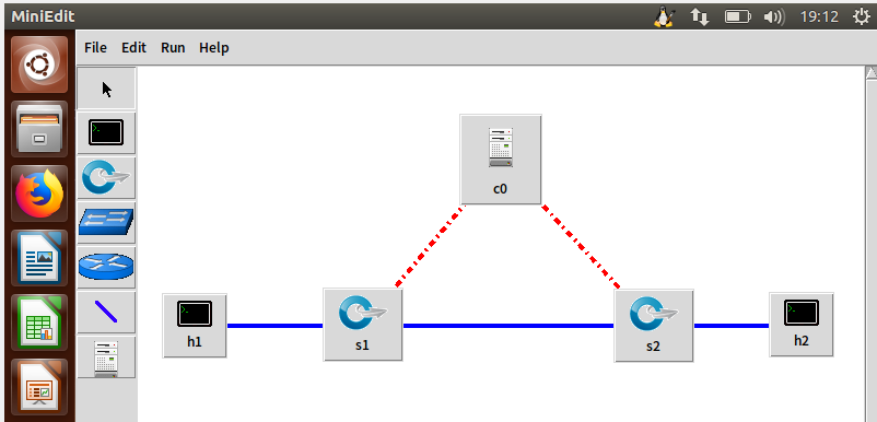
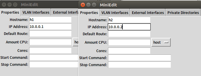
1.利用Mininet仿真平台构建如下图所示的网络拓扑,配置主机h1和h2的IP地址(h1:10.0.0.1,h2:10.0.0.2),测试两台主机之间的网络连通性


2.利用Wireshark工具,捕获拓扑中交换机与控制器之间的通信数据,对OpenFlow协议类型的各类报文(hello, features_request, features_reply, set_config, packet_in, packet_out等)进行分析,对照wireshark截图写出你的分析内容。
- hello
控制器6633端口(我最高能支持OpenFlow 1.0)---> 交换机34786端口
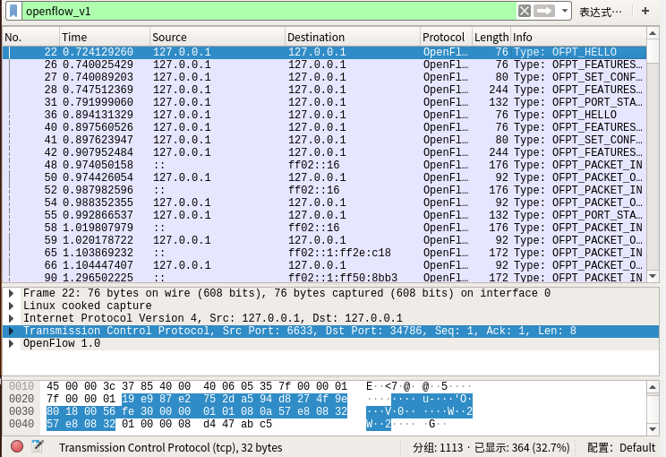
交换机34786端口(我最高能支持OpenFlow 1.3)---> 控制器6633端口
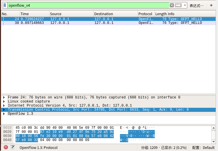
于是双方建立连接,并使用OpenFlow 1.0
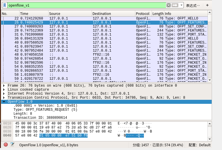
- features_request
控制器6633端口(我需要你的特征信息) ---> 交换机34786端口
- features_reply
交换机34786端口(这是我的特征信息,请查收)---> 控制器6633端口

Features 消息包括 OpenFlow Header 和 Features Reply Message
Features Reply Message结构
struct ofp_switch_features
{
    struct ofp_header header;
    uint64_t datapath_id; /*唯一标识 id 号*/
    uint32_t n_buffers; /*交缓冲区可以缓存的最大数据包个数*/
    uint8_t n_tables; /*流表数量*/
    uint8_t pad[3]; /*align to 64 bits*/
    uint32_t capabilities; /*支持的特殊功能,具体见 ofp_capabilities*/
    uint32_t actions; /*支持的动作,具体见 ofp_actions_type*/
    struct ofp_phy_port ports[0]; /*物理端口描述列表,具体见 ofp_phy_port*/
};
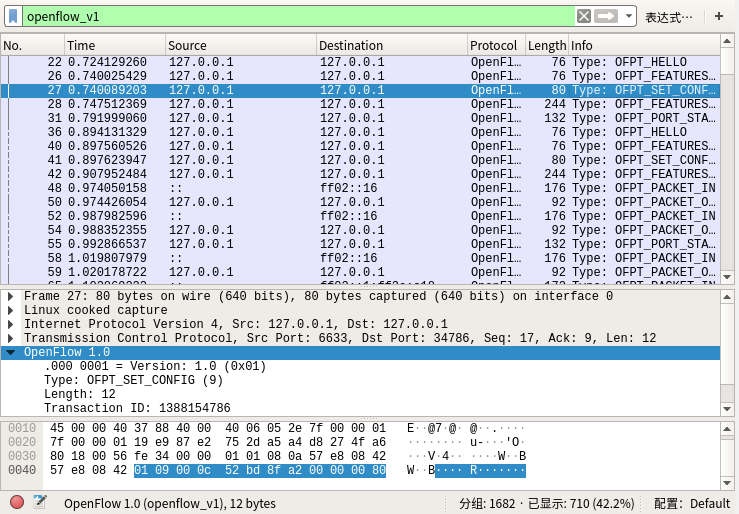
- set_config
控制器6633端口(请按照我给你的flag和max bytes of packet进行配置) ---> 交换机34786端口
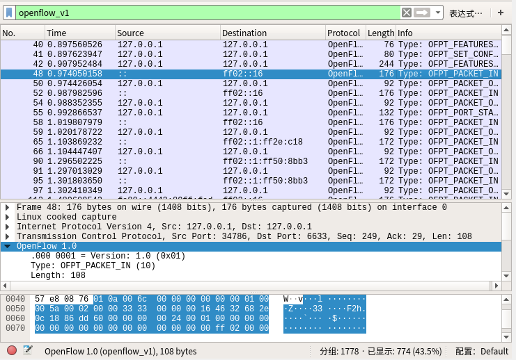
- packet_in
交换机34786端口(有数据包进来,请指示)--- 控制器6633端口
Packet_in的结构
struct ofp_packet_in
{
    struct ofp_header header;
    uint32_t buffer_id; /*Packet-in消息所携带的数据包在交换机缓存区中的ID*/
    uint16_t total_len; /*data字段的长度*/
    uint16_t in_port; /*数据包进入交换机时的端口号*/
    uint8_t reason; /*发送Packet-in消息的原因,具体见 ofp_packet_in_reason*/
    uint8_t pad;
    uint8_t data[0]; /*携带的数据包*/
};
- packet_out
控制器6633端口(请按照我给你的action进行处理) ---> 交换机34786端口

Packet_out的结构
struct ofp_packet_out
{
    struct ofp_header header;
    uint32_t buffer_id; /*交换机缓存区id,如果为-1则指定的为packet-out消息携带的data字段*/
    uint16_t in_port; /*如果buffer_id为‐1,并且action列表中指定了Output=TABLE的动作,in_port将作为data段数据包的额外匹配信息进行流表查询*/
    uint16_t actions_len; /*action列表的长度,可以用来区分actions和data段*/
    struct ofp_action_header actions[0]; /*动作列表*/
    uint8_t data[0]; /*数据缓存区,可以存储一个以太网帧,可选*/
};
