


GD32F30x_定时器输出比较模式输出方波(DMA方式)
一、工具
1、硬件:GD32F30x系列单片机
2、编译环境:KEIL
二、需求分析
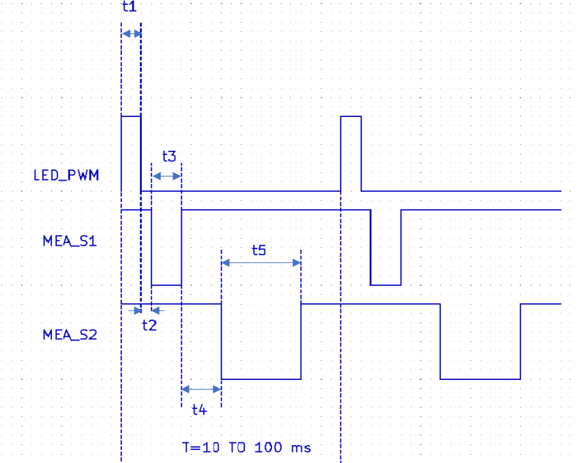
如下图所示,现要求控制单片机同时输出3路方波,并且每个方波的高低电平持续的时长是可调整的,因为对时长有着严格的要求,这就需要在方波开始输出后就不能再通过软件进行干预,完全交给单片机的硬件自己去完成。通过观察要输出方波的特点,除了LED_PWM波具备PWM波形的特点,其它两个与PWM波形有着很大的不同,于是乎想使用单片机的定时器的PWM模式输出剩余两种波形很显然行不通。这时候应该想到单片机定时器另一种比较灵活的输出方波的模式就是“输出比较模式”,当然PWM模式也是输出比较模式的一种。
通过分析,似乎找到了输出以上波形的方法,至于能否实现还需要通过代码实现并调试去验证。
那么还有一个需求也与以上输出的波形有关,那就是能够每次在t4时间段内进行电压采集,电压的变化也是受以上三个方波影响的(至于电压的采集方法我会在另一篇文章中介绍),为了保证采集的电压稳定,可以适当的在t4时间段内多次采集。熟悉单片机定时器的知道,想要每次都能够在t4时间段内采集电压,需要触发中断或者事件来实现,而能够触发中断或者事件点除了t4的开始和t4的结束也就是电平发生转换时,在t4中间是没法触发中断或者事件的,而如果只在t4的开始和t4的结束区采集电压,很可能采集到的电压并非所需要的电压。
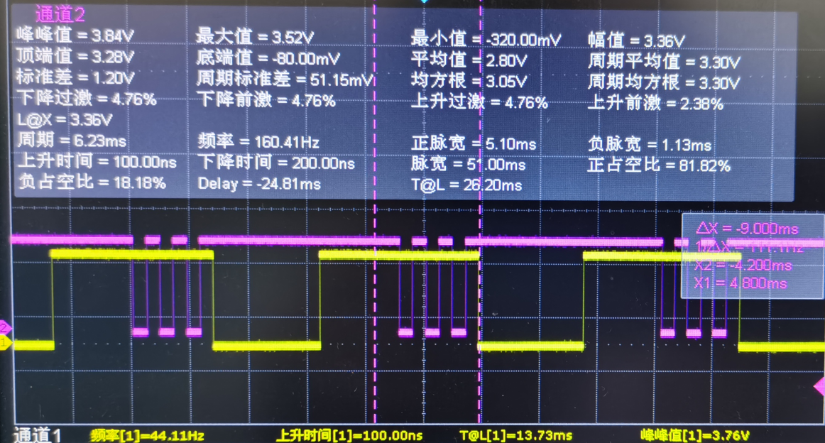
为了实现在t4时间内采集多次电压,我就想到了定时器的另一个还没有用的通道,如果让它也输出一个波形,并且使这个波形的电平能够在t4时间段内发生多次转换,那么我就可以通过触发中断的方式进行多次电压采集。理想的方式如下图紫色波形所示(当然也是我已经实现的结果,实际程序是不会输出紫色波形的,你现在看到的是我通过一个普通的IO引脚在中断中反转得到的),黄色波形是上图MEA_S2的波形。
这里需要指出,虽然我使用了定时器的一个输出比较通道输出一个波形用于采集电压,但这个波形并不占用引脚资源(你可以把这个引脚用作除定时器以外的功能),算是一个抽象出来的波形。如下图所示,通过对用户手册的解读以及实际验证,发现是可以屏蔽通道输出的。

在相关的寄存器中我们也可以找到相关的控制位,比如通道0,如下图所示,只要我们把该位置0就不要担心该引脚被用作其它功能了。

分析完上述需求后,下面就开始代码的实现。
三、代码实现
1、相关变量和参数定义, 这里需要注意所使用定时器的基地址和相关通道的偏移地址,具体值可在用户手册中查到(这里我用的是定时器4)。

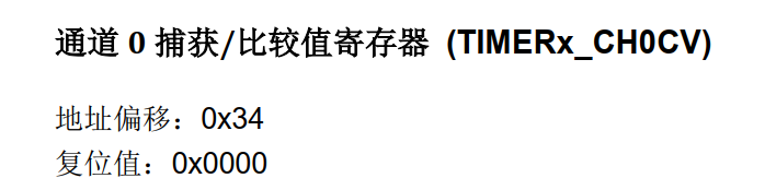
通道0的比较寄存器偏移地址:
通道1的比较寄存器偏移地址:

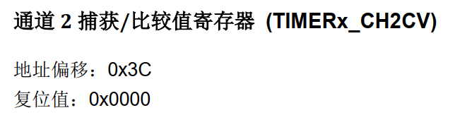
通道2的比较寄存器偏移地址:
通道3的比较寄存器偏移地址:
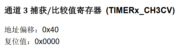
/* 定时器4通道比较寄存器地址 */
#define TIMER4_CH0CV  (TIMER4+0x34)                    /* 通道0 */
#define TIMER4_CH1CV  (TIMER4+0x38)                    /* 通道1 */
#define TIMER4_CH2CV  (TIMER4+0x3C)                    /* 通道2 */
#define TIMER4_CH3CV  (TIMER4+0x40)                    /* 通道3 */

/* 定时器比较寄存器装载值,由DMA去实现装载 */
uint16_t ch0cv_value[] = {1000, 1500, 2000, 2500, 3000, 3500, 10000};        /* 电压采集信号 */
uint16_t ch1cv_value[] = {880, 10000, 0};                                    /* LED_PWM */
uint16_t ch2cv_value[] = {4000, 8000, 10000};                                /* S2 */
uint16_t ch3cv_value[] = {893, 906, 10000};                                    /* S1 */
顺便说一下,上面比较寄存器的装载值设置是有技巧的,这是我在调试中发现的,如果有不对的地方望指出。10000是我的满度值,这一块在我的使用STM32定时器的DMA方式输出方波那篇文章中有介绍,不懂的可以去了解下。https://www.cnblogs.com/wenhao-Web/p/13820320.html
2、定时器4输出引脚配置,因为值输出三路波形,这里只配置三个GPIO引脚
/**
  * @brief 定时器4输出比较通道引脚初始化
  * @retval none
  * @author Mr.W
  * @date 2020-10-22
  */
static void bsp_timer4_gpio_cfg(void)
{
    /* 打开引脚时钟 */
    rcu_periph_clock_enable(RCU_GPIOA);
    rcu_periph_clock_enable(RCU_AF);

    /*configure PA1(TIMER4 CH1) PA2(TIMER4 CH2) PA3(TIMER4 CH3) as alternate function*/
    gpio_init(GPIOA, GPIO_MODE_AF_PP, GPIO_OSPEED_50MHZ, GPIO_PIN_1);
    gpio_init(GPIOA, GPIO_MODE_AF_PP, GPIO_OSPEED_50MHZ, GPIO_PIN_2);
    gpio_init(GPIOA, GPIO_MODE_AF_PP, GPIO_OSPEED_50MHZ, GPIO_PIN_3);
}
3、这里把DMA的四个定时器4通道都进行了配置,有一路通道虽然不需要通过引脚输出,但也要配置。
/**
  * @brief DMA配置(每个DMA通道只能同时打开一个外设请求)
  * @retval none
  * @author Mr.W
  * @date 2020-10-22
  */
static void bsp_dma_config(void)
{
    dma_parameter_struct dma_init_struct;

    /* enable DMA clock */
    rcu_periph_clock_enable(RCU_DMA1);

    /* initialize DMA channel */
    dma_deinit(DMA1,DMA_CH4);
    /* DMA channel4 initialize */
    dma_init_struct.periph_addr = (uint32_t)TIMER4_CH0CV;
    dma_init_struct.periph_inc = DMA_PERIPH_INCREASE_DISABLE;
    dma_init_struct.memory_addr = (uint32_t)ch0cv_value;
    dma_init_struct.memory_inc = DMA_MEMORY_INCREASE_ENABLE;
    dma_init_struct.periph_width = DMA_PERIPHERAL_WIDTH_16BIT;
    dma_init_struct.memory_width = DMA_MEMORY_WIDTH_16BIT;
    dma_init_struct.direction = DMA_MEMORY_TO_PERIPHERAL;
    dma_init_struct.number = 7;
    dma_init_struct.priority = DMA_PRIORITY_ULTRA_HIGH;
    dma_init(DMA1,DMA_CH4,&dma_init_struct);
    /* 使能循环模式 */
    dma_circulation_enable(DMA1,DMA_CH4);
    /* enable DMA channel4 */
    dma_channel_enable(DMA1,DMA_CH4);

    /* initialize DMA channel */
    dma_deinit(DMA1,DMA_CH3);
    /* DMA channel3 initialize */
    dma_init_struct.periph_addr = (uint32_t)TIMER4_CH1CV;
    dma_init_struct.periph_inc = DMA_PERIPH_INCREASE_DISABLE;
    dma_init_struct.memory_addr = (uint32_t)ch1cv_value;
    dma_init_struct.memory_inc = DMA_MEMORY_INCREASE_ENABLE;
    dma_init_struct.periph_width = DMA_PERIPHERAL_WIDTH_16BIT;
    dma_init_struct.memory_width = DMA_MEMORY_WIDTH_16BIT;
    dma_init_struct.direction = DMA_MEMORY_TO_PERIPHERAL;
    dma_init_struct.number = 3;
    dma_init_struct.priority = DMA_PRIORITY_ULTRA_HIGH;
    dma_init(DMA1,DMA_CH3,&dma_init_struct);
    /* 使能循环模式 */
    dma_circulation_enable(DMA1,DMA_CH3);
    /* enable DMA channel3 */
    dma_channel_enable(DMA1,DMA_CH3);

    /* initialize DMA channel */
    dma_deinit(DMA1,DMA_CH1);
    /* DMA channel1 initialize */
    dma_init_struct.periph_addr = (uint32_t)TIMER4_CH2CV;
    dma_init_struct.periph_inc = DMA_PERIPH_INCREASE_DISABLE;
    dma_init_struct.memory_addr = (uint32_t)ch2cv_value;
    dma_init_struct.memory_inc = DMA_MEMORY_INCREASE_ENABLE;
    dma_init_struct.periph_width = DMA_PERIPHERAL_WIDTH_16BIT;
    dma_init_struct.memory_width = DMA_MEMORY_WIDTH_16BIT;
    dma_init_struct.direction = DMA_MEMORY_TO_PERIPHERAL;
    dma_init_struct.number = 3;
    dma_init_struct.priority = DMA_PRIORITY_ULTRA_HIGH;
    dma_init(DMA1,DMA_CH1,&dma_init_struct);
    /* 使能循环模式 */
    dma_circulation_enable(DMA1,DMA_CH1);
    /* enable DMA channel1 */
    dma_channel_enable(DMA1,DMA_CH1);

    /* initialize DMA channel */
    dma_deinit(DMA1,DMA_CH0);
    /* DMA channel0 initialize */
    dma_init_struct.periph_addr = (uint32_t)TIMER4_CH3CV;
    dma_init_struct.periph_inc = DMA_PERIPH_INCREASE_DISABLE;
    dma_init_struct.memory_addr = (uint32_t)ch3cv_value;
    dma_init_struct.memory_inc = DMA_MEMORY_INCREASE_ENABLE;
    dma_init_struct.periph_width = DMA_PERIPHERAL_WIDTH_16BIT;
    dma_init_struct.memory_width = DMA_MEMORY_WIDTH_16BIT;
    dma_init_struct.direction = DMA_MEMORY_TO_PERIPHERAL;
    dma_init_struct.number = 3;
    dma_init_struct.priority = DMA_PRIORITY_ULTRA_HIGH;
    dma_init(DMA1,DMA_CH0,&dma_init_struct);
    /* 使能循环模式 */
    dma_circulation_enable(DMA1,DMA_CH0);
    /* enable DMA channel0 */
    dma_channel_enable(DMA1,DMA_CH0);
}
4、定时器4功能配置,这里也是配置了四个通道;不进行波形输出的那一路通道要设置成禁止,但是因为要通过它采集电压,所以要打开对应的通道中断功能。
/**
  * @brief 定时器4配置
  * @retval none
  * @author Mr.W
  * @date 2020-10-22
  */
static void bsp_timer4_cfg(void)
{
    /* ---------------------------------------------------------------------------
    TIMER1 configuration: output compare toggle mode:
    定时器频率 Frequency = systemcoreclock/((prescaler+1) * (period+1))
               10Hz = 120000000/(1200 * 10000)
    ----------------------------------------------------------------------------*/
    timer_oc_parameter_struct timer_ocintpara;
    timer_parameter_struct timer_initpara;

    rcu_periph_clock_enable(RCU_TIMER4);

    timer_deinit(TIMER4);

    /* TIMER1 configuration */
    timer_initpara.prescaler         = 1199;
    timer_initpara.alignedmode       = TIMER_COUNTER_EDGE;
    timer_initpara.counterdirection  = TIMER_COUNTER_UP;
    timer_initpara.period            = 9999;
    timer_initpara.clockdivision     = TIMER_CKDIV_DIV1;
    timer_initpara.repetitioncounter = 0;
    timer_init(TIMER4, &timer_initpara);

     /* Configuration in OC TOGGLE mode */
    timer_ocintpara.outputstate  = TIMER_CCX_ENABLE;
    timer_ocintpara.outputnstate = TIMER_CCXN_DISABLE;
    timer_ocintpara.ocpolarity   = TIMER_OC_POLARITY_HIGH;
    timer_ocintpara.ocnpolarity  = TIMER_OCN_POLARITY_HIGH;
    timer_ocintpara.ocidlestate  = TIMER_OC_IDLE_STATE_HIGH;
    timer_ocintpara.ocnidlestate = TIMER_OCN_IDLE_STATE_LOW;

    timer_channel_output_config(TIMER4, TIMER_CH_1, &timer_ocintpara);
    timer_channel_output_config(TIMER4, TIMER_CH_2, &timer_ocintpara);
    timer_channel_output_config(TIMER4, TIMER_CH_3, &timer_ocintpara);
    timer_ocintpara.outputstate = TIMER_CCX_DISABLE;
    timer_channel_output_config(TIMER4, TIMER_CH_0, &timer_ocintpara);

    /* CH10*/
    timer_channel_output_pulse_value_config(TIMER4, TIMER_CH_0, 0);
    timer_channel_output_mode_config(TIMER4, TIMER_CH_0, TIMER_OC_MODE_TOGGLE);
    timer_channel_output_shadow_config(TIMER4, TIMER_CH_0, TIMER_OC_SHADOW_DISABLE);
    /* clear channel 0 interrupt bit */
    timer_interrupt_flag_clear(TIMER4, TIMER_INT_FLAG_CH0);
    /* channel 0 interrupt enable */
    timer_interrupt_enable(TIMER4, TIMER_INT_CH0);
    /* CH1 */
    timer_channel_output_pulse_value_config(TIMER4, TIMER_CH_1, 0);
    timer_channel_output_mode_config(TIMER4, TIMER_CH_1, TIMER_OC_MODE_TOGGLE);
    timer_channel_output_shadow_config(TIMER4, TIMER_CH_1, TIMER_OC_SHADOW_DISABLE);
    /* CH2 */
    timer_channel_output_pulse_value_config(TIMER4, TIMER_CH_2, 0);
    timer_channel_output_mode_config(TIMER4, TIMER_CH_2, TIMER_OC_MODE_TOGGLE);
    timer_channel_output_shadow_config(TIMER4, TIMER_CH_2, TIMER_OC_SHADOW_DISABLE);
    /* CH3 */
    timer_channel_output_pulse_value_config(TIMER4, TIMER_CH_3, 0);
    timer_channel_output_mode_config(TIMER4, TIMER_CH_3, TIMER_OC_MODE_TOGGLE);
    timer_channel_output_shadow_config(TIMER4, TIMER_CH_3, TIMER_OC_SHADOW_DISABLE);

    /* TIMER1 update DMA request enable */
    timer_dma_enable(TIMER4, TIMER_DMA_CH0D);
    timer_dma_enable(TIMER4, TIMER_DMA_CH1D);
    timer_dma_enable(TIMER4, TIMER_DMA_CH2D);
    timer_dma_enable(TIMER4, TIMER_DMA_CH3D);

    /* auto-reload preload enable */
    timer_auto_reload_shadow_enable(TIMER4);

    timer_enable(TIMER4);
}
5、定时器4初始化,开启并设置中断优先级,并设置默认的输出频率为44Hz。
/**
  * @brief 定时器4初始化
  * @retval none
  * @author Mr.W
  * @date 2020-10-22
  */
void bsp_timer4_init(void)
{
    nvic_irq_enable(TIMER4_IRQn, 4, 0);

    bsp_timer4_gpio_cfg();
    bsp_dma_config();
    bsp_timer4_cfg();
    bsp_timer4_freq_change(44);
}
6、输出频率设置,这里单独实现一个函数是为了方便以后其它地方对频率进行更改。
/**
  * @brief 定时器4频率改变
  * @param frequency 要改变的频率值,单位Hz
  * @retval none
  * @author Mr.W
  * @date 2020-10-22
  */
void bsp_timer4_freq_change(uint32_t frequency)
{
    uint16_t prescaler;

    /* 通过设置的定时器频率计算出预分频值 */
    prescaler = (SystemCoreClock/10000)/frequency - 1;
    /* 更新预分频值 */
    timer_prescaler_config(TIMER4, prescaler, TIMER_PSC_RELOAD_NOW);
}
7、中断服务函数,中断服务函数中对定时器4通道1的比较寄存器进行了判断,如果符合要求就进行一次电压的采集,我这里共采集了6次,同时对应前面示波器显示的波形(细心的会发现我判断通道比较寄存器的值并不是从第一个开始比较的,这也是我在调试中发现的,如果从第一个开始比较会在当前值的前一次电平的转换时触发中断,与实际不符,这也是我困惑的地方,我猜测可能是DMA或者定时器缓冲区导致的滞后性造成的,如有不对的忘指出)。
/**
  * @brief  This function handles TIMER4 interrupt request.
  * @param  None
  * @retval None
  */
void TIMER4_IRQHandler(void)
{if(SET == timer_interrupt_flag_get(TIMER4, TIMER_INT_FLAG_CH0))
    {
        /* clear channel 0 interrupt bit */
        timer_interrupt_flag_clear(TIMER4, TIMER_INT_FLAG_CH0);
        /* read channel 0 capture value */
        if(TIMER_CH0CV(TIMER4) == ch0cv_value[1])
        {
            g_global_data.adc_mea[0] = adc01_get_mea_adc_value();
            g_global_data.adc_ref[0] = adc01_get_ref_adc_value();
        }
        else if(TIMER_CH0CV(TIMER4) == ch0cv_value[2])
        {
            g_global_data.adc_mea[1] = adc01_get_mea_adc_value();
            g_global_data.adc_ref[1] = adc01_get_ref_adc_value();
        }
        else if(TIMER_CH0CV(TIMER4) == ch0cv_value[3])
        {
            g_global_data.adc_mea[2] = adc01_get_mea_adc_value();
            g_global_data.adc_ref[2] = adc01_get_ref_adc_value();
        }
        else if(TIMER_CH0CV(TIMER4) == ch0cv_value[4])
        {
            g_global_data.adc_mea[3] = adc01_get_mea_adc_value();
            g_global_data.adc_ref[3] = adc01_get_ref_adc_value();
        }
        else if(TIMER_CH0CV(TIMER4) == ch0cv_value[5])
        {
            g_global_data.adc_mea[4] = adc01_get_mea_adc_value();
            g_global_data.adc_ref[4] = adc01_get_ref_adc_value();
        }
        else if(TIMER_CH0CV(TIMER4) == ch0cv_value[6])
        {
            g_global_data.adc_mea[5] = adc01_get_mea_adc_value();
            g_global_data.adc_ref[5] = adc01_get_ref_adc_value();
        }
    }
}
#endif

 浙公网安备 33010602011771号