

im6q中的: pad csi
pad 管脚
pad control: 管脚控制
csi:CMOS serial interface, 即和CMOS摄像头的通信接口。
imx 芯片的非常好的在线资料:
https://www.digi.com/resources/documentation/digidocs/90002287/reference/bsp/cont_devices_interfaces_cc6.htm?tocpath=Digi%20Embedded%20Yocto%7CSystem%20development%7CLinux%20kernel%7CLinux%20%20v4.9%20Board%20Support%20Package%7CDevices%20and%20interfaces%7C_____0
https://www.digi.com/resources/documentation/digidocs/90001546/reference/bsp/cc6/r_general_purpose_input_output.htm
https://www.digi.com/resources/documentation/digidocs/90001546/Default.htm#reference/bsp/v3-14_cc6/r_general_purpose_input_output_v3-14.htm%3FTocPath%3DAdditional%2520resources%7CLinux%2520v3.14%2520Board%2520Support%2520Package%7C_____10
一、RS232标准中的RTS与CTS
RTS,CTS------请求发送/清除发送,用于半双工时的收发切换,属于辅助流控信号。半双工的意思是说,发的时候不收,收的时候不发。那么怎么区分收发呢?缺省时是DCE向DTE发送数据,当DTE决定向DCE发数据时,先有效RTS,表示DTE希望向DCE发送。一般DCE不能马上转换收发状态,DTE就通过监测CTS是否有效来判断可否发送,这样避免了DTE在DCE未准备好时发送所导致的数据丢失。
二、MODEM硬件流控中的RTS与CTS
按照SIMCOM公司的解释,RTS和CTS是独立,
1.RTS是模块的输入端,用于MCU通知模块,MCU是否准备好,模块是否可向MCU发送信息,RTS的有效电平为低。
2.CTS是模块的输出端,用于模块通知MCU,模块是否准备好,MCU是否可向模块发送信息,CTS的有效电平为低
从文字看,RTS和CTS是独立的,不存在每次单向数据传输的发起者问题。如果主机输出RTS有效,那么模块有数据就会发往主机;如果模块输出CTS有效,那么主机就可以将数据送达模块接收。
三、通信协议中的RTS与CTS
RTS/CTS协议即请求发送/允许发送协议,相当于一种握手协议,主要用来解决"隐藏终端"问题。"隐藏终端"(Hidden Stations)是指,基站A向基站B发送信息,基站C未侦测到A也向B发送,故A和C同时将信号发送至B,引起信号冲突,最终导致发送至B的信号都丢失了。"隐藏终端"多发生在大型单元中(一般在室外环境),这将带来效率损失,并且需要错误恢复机制。当需要传送大容量文件时,尤其需要杜绝"隐藏终端"现象的发生。IEEE802.11提供了如下解决方案。在参数配置中,若使用RTS/CTS协议,同时设置传送上限字节数----一旦待传送的数据大于此上限值时,即启动RTS/CTS握手协议:首先,A向B发送RTS信号,表明A要向B发送若干数据,B收到RTS后,向所有基站发出CTS信号,表明已准备就绪,A可以发送,其余基站暂时"按兵不动",然后,A向B发送数据,最后,B接收完数据后,即向所有基站广播ACK确认帧,这样,所有基站又重新可以平等侦听、竞争信道了。
很久很久以前,计算机还没有出现,那时就已经存在了(计算机)史前的串口设备(电传打字机,工控测量设备,通信调制解调器),为了连接这些串口,EIA制定了RS232标准,采用DB25接插件,支持同步和异步串口,D型的接口可以有效防止插反。标准化给使用带来了便利。
时光荏苒,个人计算机出现了,这些已有的串口设备毫无疑问地成为了最初的外设,自然而然地RS232标准被个人计算机采纳。但是设备制造商倾向于体积更小,成本更低的接口,因此,将DB25中未使用的和支持同步模式的引脚去掉,形成DB9。最初的情况相当混乱,因为DB9只定义了信号,却没有指定信号和引脚的对应关系,各个制造商只能自行定义。幸运的是,IBM的PC成了工业标准,DB9逐渐统一到IBM的定义上来。
DB9只有9根线,遵循RS232标准。定义如下:
DTR,DSR------DTE设备准备好/DCE设备准备好。主流控信号。
RTS,CTS------请求发送/清除发送。用于半双工时,收发切换。属于辅助流控信号。半双工的意思是说,发的时候不收,收的时候不发。那么怎么区分收发呢?缺省时是DCE向DTE发送数据,当DTE决定向DCE发数据时,先有效RTS,表示DTE希望向DCE发送,一般DCE不能马上转换收发状态,DTE就通过监测CTS是否有效来判断可否发送,这样避免了DTE在DCE未准备好时发送所导致的数据丢失。全双工时,这两个信号一直有效即可。
随着计算机的日益普及,很多非RS232的串口也要接入PC机,如果为每一种新出现的串口都增加一个新的I/O口显然不现实,因为PC后面板位置有限,因此,将RS232串口和非RS232串口都通过RS232口接入是最佳方案。UART的U(通用)指的就是这个意思。早期ROM BIOS和DOS里的通信软件都是为RS232设计的,在没有检测到DCD有效前不会发送数据,因此,就连发送一个字符这样朴素的应用也要给出DCD、DTR、DSR等控制信号。因此,串口接头上要将一些控制线短接,或者干脆绕过系统软件自己写通信程序。
到此,UART的涵义就总结为:通用的 异步 (串行) I/O口。
就在UART冠以通用二字,准备一统江湖的时候,制造商们不满于它的速度、体积和灵活性(软件可配置),推出了USB和1394串口。目前,笔记本上的UART串口有被取消的趋势,因而有网友发出了“没有串口,吾谁与归”的慨叹,古今多少事,都付笑谈中,USB取代UART是后话,暂且不表。
话说自从贺氏(Hayes)公司推出了聪明猫(SmartModem),他们制定的MODEM接口就成了业界标准,自此以后,所有公司制造的兼容猫都符合贺氏标准(连AT指令也兼容)。
细观贺氏制定的MODEM串口,与RS232标准大不相同。DTR在整个通信过程中一直保持有效,DSR在MODEM上电后/可以拨号前有效(取决于软件对DSR的理解),在通信过程的任意时刻,只要DTR/DSR无效,通信过程立即终止。在某种意义上,这也可以算是流控,但肯定不是RS232所指的那种主流控。如果拘泥于RS232,你是不会理解DTR和DSR的用途的。
贺氏不但改了DTR和DSR,竟然连RTS和CTS的涵义也重新定义了。因此,RTS和CTS已经不具有最开始的意义了。从字面理解RTS和CTS,是用于半双工通信的,当DTE想从收模式改为发模式时,就有效RTS请求发送,DCE收到RTS请求后不能立即完成转换,需要一段时间,然后有效CTS通知DTE:DCE已经转到发模式,DTE可以开始发送了。在全双工时,RTS和CTS都缺省置为有效即可。然而,在贺氏的MODEM串口定义中,RTS和CTS用于硬件流控,和什么全双工/半双工一点关系也没有。 注意,硬件流控是靠软件实现的,之所以强调“硬件”二字,仅仅是因为硬件流控提供了用于流量情况指示的硬件连线,并不是说,你只要把线连上,硬件就能自己流控。如果软件不支持,光连上RTS和CTS是没有用的。
RTS和CTS硬件流控的软件算法如下:(RTS有效表示PC机可以收,CTS有效表示MODEM可以收,这两个信号互相独立,分别指示一个方向的流量情况。)
PC端处理:
发. 当发现(不一定及时发现) CTS (-3v to -15v)无效时,停止发送,
当发现(不一定及时发现) CTS (3v to 15v)有效时,恢复发送;
收. 当接收buffers中的bytes当接收buffers中的bytes>N 时,给 RTS 无效信号(-3v to -15v);
MODEM端处理:
同上,但RTS与CTS交换。
在RS232中本来CTS 与RTS 有明确的意义,但自从贺氏(HAYES ) 推出了聪明猫(SmartModem)后就有点混淆了。在RS232中RTS 与CTS 是用来半双工模式下的方向切换;HAYES Modem中的RTS ,CTS 是用来进 行硬件流控的。通常UART的RTC、CTS 的含义指后者,即用来做硬流控的。
硬流控的RTS 、CTS :RTS (Require To Send,发送请求)为输出信号,用于指示本设备准备好可接收;CTS(Clear To Send,发送清除)为输入信号,有效时停止发送。假定A、B两设备通信,A设备的RTS 连接B设备的CTS ;A设备的CTS 连接B设备 的RTS 。 前一路信号控制B设备的发送,后一路信号控制A设备的发送。对B设备的发送(A设备接收)来说,如果A设备接收缓冲快满的时发出RTS 信号(意思 通知B设备停止发送),B设备通过CTS 检测到该信号,停止发送;一段时间后A设备接收缓冲有了空余,发出RTS 信号,指示B设备开始发送数据。A设备发(B设备接收) 类似。上述功能也能在数据流中插入Xoff(特殊字符)和Xon(另一个特殊字符)信号来实现。A设备一旦接收到B设备发送过来的Xoff,立刻停止发 送;反之,如接收到B设备发送过来的Xon,则恢复发送数据给B设备。同理,B设备也类似,从而实现收发双方的速度匹配。
半双工的方向切换:RS232中使用DTR(Date Terminal Ready,数据终端准备)与DSR(Data Set Ready ,数据设备准备好)进行主流控,类似上述的RTS 与CTS 。对半双工的通信的DTE(Date Terminal Equipment,数据终端设备)与DCE(Data circuit Equipment )来说,默认的方向是DTE接收,DCE发送。如果DTE要发送数据,必须发出RTS 信号,请求发送数据。DCE收到后如果 空闲则发出CTS 回 应RTS 信 号,表示响应请求,这样通信方向就变为DTE->TCE,同时RTS 与CTS 信号必须一直保持。从这里可以看出,CTS ,TRS虽 然也有点流控的意思(如CTS 没有发出,DTE也不能发送数据),但主要是用来进行方向切换的。
如果UART只有RX、TX两个信号,要流控的话只能是软流控;如果有RX,TX,CTS ,RTS 四个信号,则多半是支持硬流控的UART;如果有 RX,TX,CTS ,RTS ,DTR,DSR 六个信号的话,RS232标准的可能性比较大。
顺便提一下:
DCD( Data Carrier Detect, 数据载波检测):DCE向DTE指示,线路上检测到载波。
RI(Ring Indicator,振铃指示):DCE向DTE指示,有呼叫接入。
====================================我是分割线=====================================================================================================
这两天基于STM32的串口做了测试。之前一直用的时候根本没有往串口协议上靠,只是能用起来解决了问题就匆匆完事。直到最近看《深入理解计算机网络》这本网络基础书,里面讲232协议以及485协议时,忽然想拿板子测试下。上面提到的CTS/RTS流控方面的应用是我之前使用串口时没有注意到的。之前在用USART做串口编程时,一般都是设备作为从机来使用,包括一些教程也都是从这样的应用来讲解。大部分的教程都是在将单片机Usart同上位机超级终端之间通过232协议转换模块进行通信。最最常见的用法就是使用串口中断进行流控(当然这种做法是推荐的,因为232的CTS/RTS不是干这个用的,本文只是那上位机的232这么测试一下。。。)
前几天看书看到232的时候,我忽然想到是不是可以用RTS/CTS来代替中断实现上位机的交互。上位机的超级终端或者串口小助手,在接收的数据的时候,可以游刃有余,因为stm32函数库里面,usart的发送数据是通过串口打印冲定义实现的,将fputs()函数进行了修改,最终使用printf函数进行输出。这种方法其实是通过函数fputs()本身进行了缓存操作,使得USART_SendData函数能一位位的将数据发出。也就是说,即是不用发送中断,我们依然能够井然有序的通过stm32的Usart的TX端口将数据发出。如下代码是stm32函数库中串口打印冲定义函数,注意是USART1。

 1 #ifdef __GNUC__
 2 /* With GCC/RAISONANCE, small printf (option LD Linker->Libraries->Small printf
 3      set to 'Yes') calls __io_putchar() */
 4 #define PUTCHAR_PROTOTYPE int __io_putchar(int ch)
 5 #else
 6 #define PUTCHAR_PROTOTYPE int fputc(int ch, FILE *f)
 7 #endif /* __GNUC__ */
 8
 9 PUTCHAR_PROTOTYPE
10 {
11     /* Place your implementation of fputc here */
12     /* e.g. write a character to the USART */
13     USART_SendData(USART1,(u8)ch);
14
15     /* Loop until the end of transmission */
16     while (USART_GetFlagStatus(USART1, USART_FLAG_TXE) == RESET);
17
18     return ch;
19 }
但是,如果我们不使用中断,而从上位机超级终端向stm32发送数据的话,你会发现,单片机只能收到你发的字符串的首个字符。其它的字符全部丢失。这就是没有做流控的结果。比如下面:
 1 int main(void)
 2 {
 3     u32 i=0xffffff;
 4     SystemInit();
 5     usart_Configuration();
 6     //NVIC_Configuration();
 7       while(1)
 8     {
 9         printf("Waveshare!\r\n");
10         while(--i);
11         i=0xffffff;
12         printf("%c",USART_ReceiveData(USART1));
       }
13 }
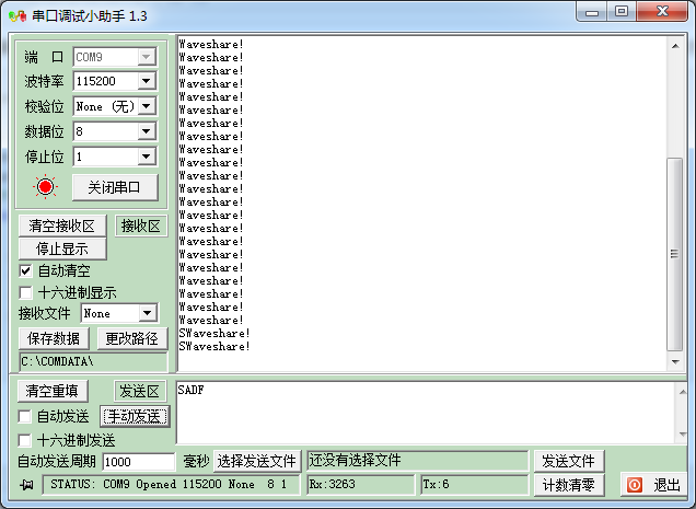
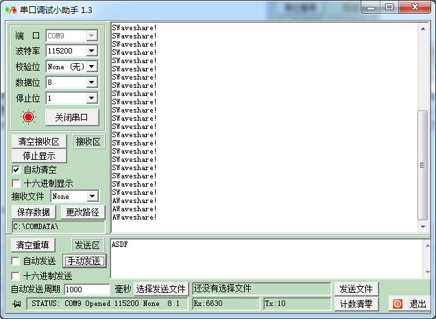
但是如果我们使用中断,或者是使用RTS/RTS做流控则不会发生这种现象。从机理上讲,上面是发生了接收溢出错误。串口状态寄存器的ORE位由于在RENE=1的情况(也就是第一个字符已经被写满数据寄存器DR)下接收到了数据,造成了数据溢出,此时SR.ORE位会置1.这点参考硬件手册,而且读取DR数据寄存器的话,仅会清除RXNE位,而不会清空数据寄存器DR。所以一直会输出S。但是如果我们发送再次发送一个字符,比如ASDF。则会发现输出字符变成了AWaveshare!道理跟之前一样,因为我们已经通过调用USART_ReceiveData()清空了RXNE,所以第一个字符A还是能读进去的,只不过当第二字字符S时又发生了前面的事情。所以,在做通信的时候必须做流控。
使用中断做流控我们就不说了,很多。这里说一下CTS/RTS。其实这个比中断简单,因为中断我们还得配置,而且中断可以写中断服务函数,所以应用广。毕竟CTS/RTS其实是用来做流控或者半双工通信的,具体的含义不一样,这里只讲232的。以RTS为例,其含义如下:

也就是说,Tx管脚接收到1个字符(默认8bit通信),硬件上RTS会产生一个置位,使得接收数据标志位RXNE=1.所以只要在软件里我们判断RXNE的状态,就可以实现流控。CTS道理一个样。故而代码可以如下:
 1 int main(void)
 2 {
 3     SystemInit();
 4 USART_CTRT_Configuartion();
 5     while(NbrOfDataToTransfer--)
 6       {
 7         USART_SendData(USART1,TxBuffer[TxCounter++]);
 8         while(USART_GetFlagStatus(USART1, USART_FLAG_TXE) == RESET); //等待发送结束
 9       }
10
11       /*Receive a string (Max RxBufferSize bytes) from the Hyperterminal ended by '\r' (Enter key) */
12     do
13     {
14         if((USART_GetFlagStatus(USART1, USART_FLAG_RXNE) != RESET)&&(RxCounter < RxBufferSize))    //0xFF:256字符
15         {
16            RxBuffer[RxCounter] = USART_ReceiveData(USART1);
17            USART_SendData(USART1, RxBuffer[RxCounter++]);
18         }
19
20     }while((RxBuffer[RxCounter - 1] != '\r')&&(RxCounter != RxBufferSize));
21
22 //串口配置函数
23
24 void USART_CTRT_Configuartion(void)
25 {
26     USART_InitTypeDef USART_InitStruct;
27
28     Rcc_Configuration();
29
30     USART_InitStruct.USART_BaudRate = 115200;
31     USART_InitStruct.USART_StopBits = USART_StopBits_1;
32     USART_InitStruct.USART_WordLength = USART_WordLength_8b;
33     USART_InitStruct.USART_Parity = USART_Parity_No;
34     USART_InitStruct.USART_HardwareFlowControl = USART_HardwareFlowControl_RTS_CTS;
35     USART_InitStruct.USART_Mode = USART_Mode_Tx | USART_Mode_Rx;
36
37     USART_Init(USART1, &USART_InitStruct);
38
39     USART_Cmd(USART1, ENABLE);
40
41     UsartGPIO_CTRT_Configuration();
42 }

完整的代码可以自己参考库函数。这里不再贴了。
引用参考:http://www.cnblogs.com/sunyubo/archive/2010/04/21/2282176.html
LinuxGPIO驱动使用其实很简单
转自:http://blog.csdn.net/drivermonkey/article/details/20132241
1.1.References
1.2.GPIO Usage from a Linux Application
1.2.1Overview
1.2.2.Configure the kernel for GPIO support in sysfs
1.2.3.Enable GPIO access from user space
1.2.4.GPIO interrupts from user space
1.2.4.1.Reference
1.2.4.2.LeopoardBoard 365 GPIO 0 connection
1.2.4.3.Using poll to monitor for GPIO 0 change
3.Example shell script making it easy to set GPIOs from the command line
1.1.References
1.2.GPIO Usage from a Linux Application
1.2.1.Overview
The following table summarizes the steps to configuring and using GPIO signals from a Linux application.
| Step | Action | Description |
|---|---|---|
| 1 | Configure the kernel for GPIO support in sysfs | Allow GPIO configuration and control from Linux applications (user space). The GPIO shoulw up in the system file system, sysfs, at /sys/class/gpio |
| 2 | Export GPIO to user space | Each GPIO is are not accessible from user space until the GPIO has been exported. You can only export a GPIO that isn't owned by a Linux kernel driver |
| 3 | Configure GPIO for input or output | To avoid hardware issues where two devices are driving the same signal, GPIOs default to be configured as an input. If you want to use the GPIO as an output, you need to change the configuration |
| 4 | Configure GPIO an an interrupt source | If you have a GPIO that is an input, and you have an application you want to block waiting for the GPIO to change level, you can configure the GPIO as an interrupt source. You also need to configure if the interrupt occurs when the GPIO signal has a rising edge, a falling edge, or interrupts on both rising and falling edges. Once configured as an interrupt, your application can read the value file and the read will block until the interrupt occurs, then your application will return from the read system call and continue running. |
The sysfs directory /sys/class/gpio contains subdirectories and files that are used for configuring and using GPIO signals from a Linux application.
| File or directory | Meaning | Notes |
|---|---|---|
| /sys/class/gpio | sysfs GPIO subdirectory | Linux applications can configuration and use GPIO signals by accessing files in this subdirectory. |
| /sys/class/gpio/export | Write-only file to expose a GPIO | Before a Linux application can configuration and use a GPIO, the GPIO first has to beexported to user space by writing the GPIO number to this file. |
| /sys/class/gpio/gpio<<<number>>> | Subdirectory for configuring and reading a specific GPIO signal | Once a GPIO has been exported to user space, a new directory appears with a set of files that allow the GPIO to be configured and used by a Linux application |
| /sys/class/gpio/gpio<<<number>>>/direction | Read-write supporting values of inand out | |
| /sys/class/gpio/gpio<<<number>>>/value | Read-write supporting values of 0 and1 | |
| /sys/class/gpio/gpio<<<number>>>/edge | Read-write supporting values ofrising, falling, and both | Check your processor documentation. Not all GPIO pins support interrupts. |
1.2.2.Configure the kernel for GPIO support in sysfs
Symbol: GPIO_SYSFS [=y]
  Prompt: /sys/class/gpio/... (sysfs interface)
    Defined at drivers/gpio/Kconfig:51
    Depends on: GPIOLIB && SYSFS && EXPERIMENTAL
     Location:
      -> Kernel configuration
        -> Device Drivers
         -> GPIO Support (GPIOLIB [=y])
1.2.3.Enable GPIO access from user space
GPIO=22

cd /sys/class/gpio
ls
echo $GPIO > export
ls
Notice on the first ls that gpio22 doesn't exist, but does after you export GPIO 22 to user space.
cd /sys/class/gpio/gpio$GPIO
ls
There are files to set the direction and retrieve the current value.
echo "in" > direction
cat value
You can configure the GPIO for output and set the value as well.
echo "out" > direction
echo 1 > value
1.2.4.PIO interrupts from user space
1.2.4.1.Reference
- http://bec-systems.com/site/281/how-to-implement-an-interrupt-driven-gpio-input-in-linux
- http://www.spinics.net/lists/linux-newbie/msg01028.html
- elinux.org/images/d/d4/Celf-gpio.odp
- http://docs.blackfin.uclinux.org/doku.php?id=linux-kernel:drivers:gpio-sysfs
1.2.4.2.eopoardBoard 365 GPIO 0 connection
On the LeopardBoard 365, the only GPIO I could find that was usable for interrupt input is GPIO0, also called CMOS_TRIGGER in the schematics. In looking at the schematics resistor R12 is not loaded and one of the pads connects to CMOS_TRIGGER. This R12 pad is the one closest to R11. If you hold the leopardboard 365 with the SD card slot facing you and rotate the board until the SD card slot is on the bottom edge, the the R12 pads are to the right of J6 and to the left of the SD card slot upper left corner.

1.2.4.3.sing poll() to monitor for GPIO 0 change
The gpio-int-test.c program (or gpiopin.cpp for those who prefer C++) shows one way of using the sysfs file /sys/class/gpio/gpio0/value to block program execution using poll() until the input level on GPIO0 changes. The tricky part was figuring out to use POLLPRI instead of POLLIN as the event to monitor. You must have GPIO support in sysfs for this program to work (or you will not see the /sys/class/gpio directory).
The gpio-int-test.c program uses poll() to wake up every 3 seconds (using poll() timeout mechanism) at which time it prints a period. The poll() function is also watching for input from stdin and for an interrupt from GPIO 0.
Here is an example output. I started gpio-int to watch GPIO 0. I waited around 12 seconds (4 timeout periods), then pressed the letter 'a' twice followed by enter key. Then I shorted the haywire to 3.3V that is accessible on pin 5 on the JTAG connector. JTAG pin 5 is across from the JTAG missing pin). I exited the program using cntl-C.
/root # gpio-int 0

....aa

poll() stdin read 0xA61

poll() stdin read 0xA61

poll() stdin read 0xA0A
..
poll() GPIO 0 interrupt occurred (len 0)

poll() GPIO 0 interrupt occurred (len 0)

poll() GPIO 0 interrupt occurred (len 0)

poll() GPIO 0 interrupt occurred (len 0)
..^C
2.Viewing GPIO Configuration
You can use debugfs to videw the current GPIO configuration. You may also be able to use debugfs to see if the GPIO pin is multiplex as a GPIO or is dedicated to some other function.
Configure the kernel to enable debugfs:
Symbol: DEBUG_FS [=y]
   Prompt: Debug Filesystem
     Defined at lib/Kconfig.debug:77
     Depends on: SYSFS
     Location:
       -> Kernel configuration
         -> Kernel hacking
Boot the target hardware and mount debugfs:
mount -t debugfs none /sys/kernel/debug
Dump the GPIO configuration.
cat /sys/kernel/debug/gpio
Dump the pin multiplexing configuration.
cat /sys/kernel/debug/omap_mux/board      # for OMAP
cat /sys/kernel/debug/dm365_mux           # for DM36x
3.Example shell script making it easy to set GPIOs from the command line
If you want to have a simple way to control a GPIO signal from the Linux command line, try the gpio.sh script below.
For examaple, if you want to read the value of GPIO 72 without setting its direction, try
gpio.sh 72
If you want to force GPIO 35 to be in input and read the current value, try
gpio.sh 35 in
If you want to configure GPIO 4 to be an output and set the value high, try
gpio.sh 4 out 1
For the script below to work, you need to first make sure you have build busybox with printf enabled.
#!bin/sh

show_usage()
{
    printf "\ngpio.sh <gpio pin number> [in|out [<value>]]\n"
}

if [ \( $# -eq 0 \) -o \( $# -gt 3 \) ] ; then
    show_usage
    printf "\n\nERROR: incorrect number of parameters\n"
    exit 255
fi

#doesn't hurt to export a gpio more than once
echo $1 > /sys/class/gpio/export

if [  $# -eq 1 ] ; then
   cat /sys/class/gpio/gpio$1/value
   exit 0
fi

if [ \( "$2" != "in" \) -a  \( "$2" != "out" \) ] ; then
    show_usage
    printf "\n\nERROR: second parameter must be 'in' or 'out'\n"
    exit 255
fi

echo $2 > /sys/class/gpio/gpio$1/direction

if [  $# -eq 2 ] ; then
   cat /sys/class/gpio/gpio$1/value
   exit 0
fi


VAL=$3

if [ $VAL -ne 0 ] ; then
    VAL=1
fi

echo $VAL > /sys/class/gpio/gpio$1/value
4.Example of C/C++ code making it easier to set GPIOs
/* Copyright (c) 2011, RidgeRun
 * All rights reserved.
 *
 * Redistribution and use in source and binary forms, with or without
 * modification, are permitted provided that the following conditions are met:
 * 1. Redistributions of source code must retain the above copyright
 *    notice, this list of conditions and the following disclaimer.
 * 2. Redistributions in binary form must reproduce the above copyright
 *    notice, this list of conditions and the following disclaimer in the
 *    documentation and/or other materials provided with the distribution.
 * 3. All advertising materials mentioning features or use of this software
 *    must display the following acknowledgement:
 *    This product includes software developed by the RidgeRun.
 * 4. Neither the name of the RidgeRun nor the
 *    names of its contributors may be used to endorse or promote products
 *    derived from this software without specific prior written permission.
 *
 * THIS SOFTWARE IS PROVIDED BY RIDGERUN ''AS IS'' AND ANY
 * EXPRESS OR IMPLIED WARRANTIES, INCLUDING, BUT NOT LIMITED TO, THE IMPLIED
 * WARRANTIES OF MERCHANTABILITY AND FITNESS FOR A PARTICULAR PURPOSE ARE
 * DISCLAIMED. IN NO EVENT SHALL RIDGERUN BE LIABLE FOR ANY
 * DIRECT, INDIRECT, INCIDENTAL, SPECIAL, EXEMPLARY, OR CONSEQUENTIAL DAMAGES
 * (INCLUDING, BUT NOT LIMITED TO, PROCUREMENT OF SUBSTITUTE GOODS OR SERVICES;
 * LOSS OF USE, DATA, OR PROFITS; OR BUSINESS INTERRUPTION) HOWEVER CAUSED AND
 * ON ANY THEORY OF LIABILITY, WHETHER IN CONTRACT, STRICT LIABILITY, OR TORT
 * (INCLUDING NEGLIGENCE OR OTHERWISE) ARISING IN ANY WAY OUT OF THE USE OF THIS
 * SOFTWARE, EVEN IF ADVISED OF THE POSSIBILITY OF SUCH DAMAGE.
 */

#include <stdio.h>
#include <stdlib.h>
#include <string.h>
#include <errno.h>
#include <unistd.h>
#include <fcntl.h>
#include <poll.h>

 /****************************************************************
 * Constants
 ****************************************************************/

#define SYSFS_GPIO_DIR "/sys/class/gpio"
#define POLL_TIMEOUT (3 * 1000) /* 3 seconds */
#define MAX_BUF 64

/****************************************************************
 * gpio_export
 ****************************************************************/
int gpio_export(unsigned int gpio)
{
    int fd, len;
    char buf[MAX_BUF];

    fd = open(SYSFS_GPIO_DIR "/export", O_WRONLY);
    if (fd < 0) {
        perror("gpio/export");
        return fd;
    }

    len = snprintf(buf, sizeof(buf), "%d", gpio);
    write(fd, buf, len);
    close(fd);

    return 0;
}

/****************************************************************
 * gpio_unexport
 ****************************************************************/
int gpio_unexport(unsigned int gpio)
{
    int fd, len;
    char buf[MAX_BUF];

    fd = open(SYSFS_GPIO_DIR "/unexport", O_WRONLY);
    if (fd < 0) {
        perror("gpio/export");
        return fd;
    }

    len = snprintf(buf, sizeof(buf), "%d", gpio);
    write(fd, buf, len);
    close(fd);
    return 0;
}

/****************************************************************
 * gpio_set_dir
 ****************************************************************/
int gpio_set_dir(unsigned int gpio, unsigned int out_flag)
{
    int fd, len;
    char buf[MAX_BUF];

    len = snprintf(buf, sizeof(buf), SYSFS_GPIO_DIR  "/gpio%d/direction", gpio);

    fd = open(buf, O_WRONLY);
    if (fd < 0) {
        perror("gpio/direction");
        return fd;
    }

    if (out_flag)
        write(fd, "out", 4);
    else
        write(fd, "in", 3);

    close(fd);
    return 0;
}

/****************************************************************
 * gpio_set_value
 ****************************************************************/
int gpio_set_value(unsigned int gpio, unsigned int value)
{
    int fd, len;
    char buf[MAX_BUF];

    len = snprintf(buf, sizeof(buf), SYSFS_GPIO_DIR "/gpio%d/value", gpio);

    fd = open(buf, O_WRONLY);
    if (fd < 0) {
        perror("gpio/set-value");
        return fd;
    }

    if (value)
        write(fd, "1", 2);
    else
        write(fd, "0", 2);

    close(fd);
    return 0;
}

/****************************************************************
 * gpio_get_value
 ****************************************************************/
int gpio_get_value(unsigned int gpio, unsigned int *value)
{
    int fd, len;
    char buf[MAX_BUF];
    char ch;

    len = snprintf(buf, sizeof(buf), SYSFS_GPIO_DIR "/gpio%d/value", gpio);

    fd = open(buf, O_RDONLY);
    if (fd < 0) {
        perror("gpio/get-value");
        return fd;
    }

    read(fd, &ch, 1);

    if (ch != '0') {
        *value = 1;
    } else {
        *value = 0;
    }

    close(fd);
    return 0;
}


/****************************************************************
 * gpio_set_edge
 ****************************************************************/

int gpio_set_edge(unsigned int gpio, char *edge)
{
    int fd, len;
    char buf[MAX_BUF];

    len = snprintf(buf, sizeof(buf), SYSFS_GPIO_DIR "/gpio%d/edge", gpio);

    fd = open(buf, O_WRONLY);
    if (fd < 0) {
        perror("gpio/set-edge");
        return fd;
    }

    write(fd, edge, strlen(edge) + 1);
    close(fd);
    return 0;
}

/****************************************************************
 * gpio_fd_open
 ****************************************************************/

int gpio_fd_open(unsigned int gpio)
{
    int fd, len;
    char buf[MAX_BUF];

    len = snprintf(buf, sizeof(buf), SYSFS_GPIO_DIR "/gpio%d/value", gpio);

    fd = open(buf, O_RDONLY | O_NONBLOCK );
    if (fd < 0) {
        perror("gpio/fd_open");
    }
    return fd;
}

/****************************************************************
 * gpio_fd_close
 ****************************************************************/

int gpio_fd_close(int fd)
{
    return close(fd);
}

/****************************************************************
 * Main
 ****************************************************************/
int main(int argc, char **argv, char **envp)
{
    struct pollfd fdset[2];
    int nfds = 2;
    int gpio_fd, timeout, rc;
    char *buf[MAX_BUF];
    unsigned int gpio;
    int len;


    if (argc < 2) {
        printf("Usage: gpio-int <gpio-pin>\n\n");
        printf("Waits for a change in the GPIO pin voltage level or input on stdin\n");
        exit(-1);
    }

    gpio = atoi(argv[1]);

    gpio_export(gpio);
    gpio_set_dir(gpio, 0);
    gpio_set_edge(gpio, "rising");
    gpio_fd = gpio_fd_open(gpio);

    timeout = POLL_TIMEOUT;

    while (1) {
        memset((void*)fdset, 0, sizeof(fdset));

        fdset[0].fd = STDIN_FILENO;
        fdset[0].events = POLLIN;

        fdset[1].fd = gpio_fd;
        fdset[1].events = POLLPRI;

        rc = poll(fdset, nfds, timeout);

        if (rc < 0) {
            printf("\npoll() failed!\n");
            return -1;
        }

        if (rc == 0) {
            printf(".");
        }

        if (fdset[1].revents & POLLPRI) {
            len = read(fdset[1].fd, buf, MAX_BUF);
            printf("\npoll() GPIO %d interrupt occurred\n", gpio);
        }

        if (fdset[0].revents & POLLIN) {
            (void)read(fdset[0].fd, buf, 1);
            printf("\npoll() stdin read 0x%2.2X\n", (unsigned int) buf[0]);
        }

        fflush(stdout);
    }

    gpio_fd_close(gpio_fd);
    return 0;
}
Using GPIO from a linux shell on iMX based products
https://www.technexion.com/support/knowledgebase/using-gpio-from-a-linux-shell-on-imx-based-products/
Summary
This guide teaches how to find the correct GPIO number for a pin. It also shows how to read the value of an input gpio, or set the value of an output gpio.
Background
The iMX-series CPUs (iMX5, iMX6, iMX6SX, iMX6UL, iMX7D, iMX8M, …) refer to GPIOs using two parameters: a bank number and an io number. For example typical GPIOs can be GPIO2_IO12 or GPIO1_IO00.
The bank refers to the internal GPIO controller inside the CPU, and one controller has 32 IOs. For the example gpios, GPIO2_IO12 uses bank 2 and io 12.
Finding gpio number
To use a GPIO its number needs to be known. If we know the bank and io number, the kernel’s number can be calculated with
N = (BANK – 1) * 32 + IO
For example GPIO2_IO12 would get the kernel GPIO number
N = (2 – 1) * 32 + 12 = 44
Finding out which bank and io a pin has, one has to consult the schematics.
Once the pin name has been found, it’s corresponding GPIO bank and io number can be looked up either in the processor’s reference manual, or from within the kernel source code. In the latter the pinmuxes are defined in the device tree folder arch/arm/boot/dts/, usually in a file named *pinfunc.h or so.
A pin can only have one pinmux as GPIO, and a GPIO+IO can only be present on one pin (it is a one-to-one mapping).
Setting and reading a GPIO
The GPIOs are typically accessible in /sys/class/gpio folder.
Each GPIO has its own folder. For instance GPIO 44 will use folder named /sys/class/gpio/gpio44. If the folder is not present, the GPIO needs to be exported first. This can be done by:# echo 44 > /sys/class/gpio/export
and similarily unexported by# echo 44 > /sys/class/gpio/unexport
Inside the gpio folder are the two important ‘files’: value and direction.
To read the value of a gpio, first set the gpio as an input by# echo in > /sys/class/gpio/gpio44/direction
and then read the value by# cat /sys/class/gpio/gpio44/value
Similarily, set the value of output GPIOs by first setting the direction# echo out > /sys/class/gpio/gpio44/direction
and then set the value low by# echo 0 > /sys/class/gpio/gpio44/value
or to high# echo 1 > /sys/class/gpio/gpio44/value
NB: On products that have isolated GPIOs this semantic is reversed, use 1 for low and 0 for high.
GPIO expanders
GPIO expanders appear on some TechNexion products. Typically the GPIOs on expander chips do not follow the bank/io priniciple. Instead
the GPIOs are directly mapped to the end of the gpio number space(即更简单了,就是相应的数字). Look for folders name gpiochip* in /sys/class/gpio/.
Easiest way to find the expander is to look at the ngpio file in the gpiochipN folder. A 8-bit expander will have an 8 in ngpio.
Then the GPIO numbers can be found by looking at the base file. A value of, say, 208 means that the expanders gpios will be number
208, 209, 210, …
When the GPIO numbers have been identified, they can be exported and used just as the CPU native banked GPIOs.
Future of GPIOs
Since 2016 there is a movement in Linux kernel community to move away from the sysfs based GPIOs to character devices (/dev/gpiochipN). The current /sys/class/gpio/ folder is likely to be around for quite some time – but applications that want to be futureproof should considering
using the character devices instead.
Troubleshooting GPIOs
Sometimes it might appear that writes to the value file have no effect, the value stays 0 and measuring the voltage on the gpio line gives the same result.
Some common causes for this type of problems are:
- The pin is already used by something else, typically defined to do so in the device tree. Look there first.
- The pin number is wrong. Do the math again. 🙂
- The pin is not muxed as GPIO after all. Re-check the device tree.
- The pin is an isolated GPIO and cannot be set in desired mode
- The pin is an isolated output GPIO, and there is no external power connected to the GPIO port
imx6设备树pinctrl解析
https://www.cnblogs.com/fah936861121/articles/7085308.html
1、普通设置
在配置串口时,pinctrl的配置信息如下所示:
- &uart2 {
- pinctrl-names = "default";
- pinctrl-0 = <&pinctrl_uart2>;
- status = "okay";
- };
- //。。。。。。。。
- pinctrl_uart2: uart2grp {
- fsl,pins = <
- MX6QDL_PAD_SD4_DAT7__UART2_TX_DATA 0x1b0b1
- MX6QDL_PAD_SD4_DAT4__UART2_RX_DATA 0x1b0b1
- >;
- };

这里的MX6QDL_PAD_SD4_DAT7__UART2_TX_DATA在imx6dl-pinfunc.h文件中有如下定义:
- MX6QDL_PAD_SD4_DAT7__UART2_TX_DATA 0x35c 0x744 0x000 0x2 0x0
将管脚的配置展开即: 0x35c 0x744 0x000 0x2 0x0 0x1b0b1
想知道这六个值都是什么意思,可以从两个路出发:①查找解读dts的文件,即看内核源码;②在网上查找相关知识。
1.1 查看源码对设备树文件的解读
首先在imx6dl-pinfunc.h文件中有对前5个变量的解释,如下图:
为了验证这5个变量,并查找第6个变量的含义,我们打开读取设备树文件的代码。
读取dts文件的文件为:drivers/pinctrl/freescale/pinctrl-imx.c,实现函数名为:static int imx_pinctrl_parse_groups(。。。),如下:
- static int imx_pinctrl_parse_groups(struct device_node *np,
- struct imx_pin_group *grp,
- struct imx_pinctrl_soc_info *info,
- u32 index)
- {
- int size, pin_size;
- const __be32 *list;
- int i;
- u32 config;
- dev_dbg(info->dev, "group(%d): %s\n", index, np->name);
- if (info->flags & SHARE_MUX_CONF_REG)
- pin_size = SHARE_FSL_PIN_SIZE;
- else
- pin_size = FSL_PIN_SIZE;
- /* Initialise group */
- grp->name = np->name;
- /*
- * the binding format is fsl,pins = <PIN_FUNC_ID CONFIG ...>,
- * do sanity check and calculate pins number
- */
- list = of_get_property(np, "fsl,pins", &size);
- if (!list) {
- dev_err(info->dev, "no fsl,pins property in node %s\n", np->full_name);
- return -EINVAL;
- }
- /* we do not check return since it's safe node passed down */
- if (!size || size % pin_size) {
- dev_err(info->dev, "Invalid fsl,pins property in node %s\n", np->full_name);
- return -EINVAL;
- }
- grp->npins = size / pin_size;
- grp->pins = devm_kzalloc(info->dev, grp->npins * sizeof(struct imx_pin),
- GFP_KERNEL);
- grp->pin_ids = devm_kzalloc(info->dev, grp->npins * sizeof(unsigned int),
- GFP_KERNEL);
- if (!grp->pins || ! grp->pin_ids)
- return -ENOMEM;
- for (i = 0; i < grp->npins; i++) {
- u32 mux_reg = be32_to_cpu(*list++);
- u32 conf_reg;
- unsigned int pin_id;
- struct imx_pin_reg *pin_reg;
- struct imx_pin *pin = &grp->pins[i];
- if (info->flags & SHARE_MUX_CONF_REG)
- conf_reg = mux_reg;
- else
- conf_reg = be32_to_cpu(*list++);
- pin_id = mux_reg ? mux_reg / 4 : conf_reg / 4;
- pin_reg = &info->pin_regs[pin_id];
- pin->pin = pin_id;
- grp->pin_ids[i] = pin_id;
- pin_reg->mux_reg = mux_reg;
- pin_reg->conf_reg = conf_reg;
- pin->input_reg = be32_to_cpu(*list++);
- pin->mux_mode = be32_to_cpu(*list++);
- pin->input_val = be32_to_cpu(*list++);
- /* SION bit is in mux register */
- config = be32_to_cpu(*list++);
- if (config & IMX_PAD_SION)
- pin->mux_mode |= IOMUXC_CONFIG_SION;
- pin->config = config & ~IMX_PAD_SION;
- dev_dbg(info->dev, "%s: 0x%x 0x%08lx", info->pins[pin_id].name,
- pin->mux_mode, pin->config);
- }
- return 0;
- }
这段代码中list = of_get_property(np, "fsl,pins", &size);实现了读取dts文件中的fsl,pin属性值,并保存在了list指针变量中。紧接着,分别将list中的值mux_reg、conf_reg、input_reg、mux_mode、input_val、config六个变量中,由名字可以猜测个大概,前5个得以验证,第六个表示config,config的值说白了就是对寄存器配置(上拉电阻、频率等等)的值,就是pad_ctrl的值。
因此对应关系如下:
0x35c | 0x744 | 0x000 | 0x2 | 0x0 | 0x1b0b1
---------------------------------------------------------------------------------------------------------
mux_ctrl_ofs | pad_ctrl_ofs | sel_input_ofs | mux_mode | sel_input | pad_ctrl
以上参数在参考手册怎么确定的呢?由于是对复用管脚的配置,于是在管脚复用的章节(IOMUXC)中查找。但是现确定pad name才方便,于是定义在External Signals and Pin Multiplexing章节,搜索MX6QDL_PAD_SD4_DAT7__UART2_TX_DATA的中间部分:SD4_DAT7,如下图
可知UART2_TX_DATA是属于SD4_DAT7的ALT2,于是mux_mode=0x2即可。上图表格中最后一列SW_PAD_CTL_PAD_SD4_DATA7是config配置需要查找的名称,跳到管脚复用的章节(IOMUXC)中,找到SW_PAD_CTL_PAD_SD4_DATA7,如下所示:
如果直接取默认值的话结果是config=0x1b0b0,这里可以根据自己的需要(硬件)更改为与自己的板子匹配的值,我把最后SRE的值设置为1,即Fast Slew Rate,如下图说明:
OK,接下来是mux_ctrl_ofs、pad_ctrl_ofs、sel_input_ofs三个偏移值,这些值都是在复用管脚的章节确定的。因为pad name为SD4_DATA7,所以在找的时候可以拿它当关键字。
首先是mux_ctrl_ofs,找到IOMUXC_SW_MUX_CTL_PAD*开头的部分,结尾选择SD4_DATA7即可,如下图,
由”Address: 20E_0000h base + 35Ch offset = 20E_035Ch“中可知offset=35C,即mux_ctrl_oft=0x35c
其他的查找方法类似。pad_ctrl_ofs,查找IOMUXC_SW_PAD_CTL_PAD_SD4_DATA7一节,可知偏移值pad_ctrl_ofs=0x744
sel_input_ofs查找IOMUXC章节以SELECT_INPUT结尾的部分,中间选择UART2_TX,如果没有这里sel_input_ofs=0x000即可,对应的sel_input为0即可。如果有例如IOMUXC_UART2_UART_RX_DATA_SELECT_INPUT,即uart的rx管脚配置,如下图,所以RX的sel_input_ofs=0x904,这里选择对应的值“110 SD4_DATA4_ALT2 — Selecting ALT2 mode of pad SD4_DAT4 for UART2_RX_DATA..“所以RX(MX6QDL_PAD_SD4_DAT4__UART2_RX_DATA)的sel_input=0x6。
2、特殊设置
首先还是先看代码,看看到底特殊到哪里。
- pinctrl_gpio_leds: gpioledsgrp {
- fsl,pins = <
- MX6QDL_PAD_DISP0_DAT21__GPIO5_IO15 0x80000000
- >;
- };
- pinctrl_i2c2: i2c2grp {
- fsl,pins = <
- MX6QDL_PAD_EIM_EB2__I2C2_SCL 0x4001b8b1
- MX6QDL_PAD_KEY_ROW3__I2C2_SDA 0x4001b8b1
- >;
- };
可以看出来特殊的配置就是后面的值也就是上一篇讲的config(pad_ctrl)的值改变了,变为0x80000000和0x4001b8b1了,当我们查找相应的pad值时是这样的:
这明显不和常理,在上图中显示高15位全部置0,取值也没啥用,那么为什么设置为0x80000000和0x4001b8b1呢?在网上搜罗一番没有任何有帮助的文档,只能靠自己了。还是老思路,查找设备树文件的读取源码,drivers/pinctrl/freescale/pinctrl-imx.c中,找到了惊喜!!!代码如下
- /* The bits in CONFIG cell defined in binding doc*/
- #define IMX_NO_PAD_CTL 0x80000000 /* no pin config need */
- #define IMX_PAD_SION 0x40000000 /* set SION */</span>
- for (i = j = 0; i < grp->npins; i++) {
- if (!(grp->pins[i].config & IMX_NO_PAD_CTL)) {
- new_map[j].type = PIN_MAP_TYPE_CONFIGS_PIN;
- new_map[j].data.configs.group_or_pin =
- pin_get_name(pctldev, grp->pins[i].pin);
- new_map[j].data.configs.configs = &grp->pins[i].config;
- new_map[j].data.configs.num_configs = 1;
- j++;
- }
- }
也就是说,对于IMX_NO_PAD_CTL(0X80000000)来说,只要在设备树中的
fsl, pins = <
MX6QDL_PAD_XXX_XXX 0xxxxx
>;
的fsl, pins属性中的配置config(pad_ctrl)的第31位为1,就说明该管脚的配置config(pad_ctrl)无效,比如
- fsl,pins = <
- MX6QDL_PAD_DISP0_DAT21__GPIO5_IO15 0x80000000
- >;
这里0x80000000,这个数的第31位为1,那么说明该管脚(MX6QDL_PAD_DISP0_DAT21__GPIO5_IO15)的config(pad_ctrl)无效,不同于上面1.1章节的普通设置那里config(pad_ctrl)值为0x1b0b1,0x1b0b1的第31位为0,所以config(pad_ctrl)有效
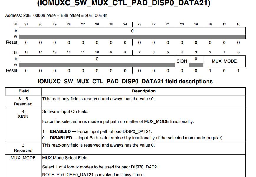
同理0x40000000表示设置了SION。SION是什么意思呢?可以查看但是0x4001b8b1表示什么意思呢,可以查看imx6规格书,如下:
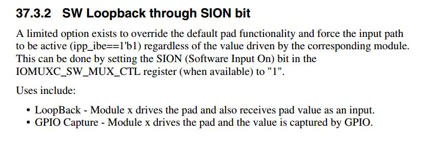
即只要设置了SION位为1,那么就强制设置这个pad为某个输入功能,不管MUX_MODE设置了何种mode方式,比如IOMUXC_SW_MUX_CTL_PAD_DISP0_DATA21的SION位如果设置为1,那么Force input path of pad DISP0_DAT21,即强制设置为DISP0_DAT21功能,不管你的MUX_MODE设置了什么值。也就是说fsl, pins属性中的配置config(pad_ctrl)的第30位为1,那么在内核源码解析设备树时就会把对应的寄存器的SION位置为1.
我们可以从注释(/* The bits in CONFIG cell defined in binding doc*/)可以找到方向,即取binding doc中找,所以打开Documentation/devicetree/bindings/pinctrl目录下的fsl,imx6dl-pinctrl.txt文件,里面有关于SION的介绍,如下:
那么这个在设备树上如何实现呢?
比如,普通设置里IOMUXC_SW_PAD_CTL_PAD_DISP0_DATA21中config = 0x1b8b1。若要设置SION功能,那么IOMUXC_SW_PAD_CTL_PAD_DISP0_DATA21中config = 0x4001b8b1,就是这里config的第30位为1
支付宝扫一扫捐赠

微信公众号: 共鸣圈
欢迎讨论,邮件: 924948$qq.com 请把$改成@
QQ群:263132197
QQ: 924948

 浙公网安备 33010602011771号