
寄存器和库函数的操作
寄存器的使用
寄存器位操作
(1) 清零,
&= ~( 对应位 );原理:
x & 1 = x;x & 0 = 0(2) 置一,
|= ( 对应位 );原理:
x | 1 = 1;x | 0 = x(3) 取反,
^= ( 对应位 );原理:
x ^ 1 = ~x;x | 0 = x
寄存器位取反:可以将GPIO的 “ 端口位” 的状态反转,0 => 1; 1 => 0
IO口状态反转:
1、需要输出 0/1
2、需要反转时,寄存器ODR
^= ( )
如何操作STM32的寄存器
例如:
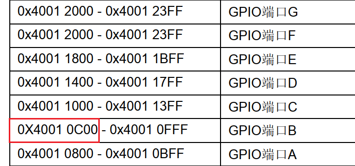
#define	 _GPIOB_BASE			0X40010C00		//从手册中找到GPIOB的基地址
#define  GPIOB_CRL  			(*(unsigned int *)(_GPIOB_BASE + 0X00))
#define  GPIOB_CRH  			(*(unsigned int *)(_GPIOB_BASE + 0X04))
#define  GPIOB_IDR  			(*(unsigned int *)(_GPIOB_BASE + 0X08))
#define  GPIOB_ODR  			(*(unsigned int *)(_GPIOB_BASE + 0X0C))
//(_GPIOB_BASE + 0X00),获取寄存器的“地址值”
//(unsigned int *)(_GPIOB_BASE + 0X00),将该 “地址值” 转换为32位的 “指针” 类型
//*(unsigned int *)(_GPIOB_BASE + 0X0C),*解指针,操作对应地址的 “内容”
配置代码:
//配置 GPIOB5 为 推挽输出
RCC->APB2ENR |= (0x1<<3);	//开启PB时钟
GPIOB_CRL &= ~(0xF<<20);
GPIOB_CRL |=  (0x3<<20);	//推挽输出
GPIOB_ODR |=  (0x1<<5);		//PB5=1
#define LED0_PORT GPIOB
#define LED0_PIN	5
#define LED1_PORT GPIOE
#define LED1_PIN	5

#define Led_On(port, pin)		(port->ODR &= ~(0x1<<pin))
#define Led_Off(port, pin)		(port->ODR |=  (0x1<<pin))
#define Led_Toggle(port, pin)	(port->ODR ^=  (0x1<<pin))
//  Toggle/ˈtɒɡl/ v.切换, n.开关		将GPIO的端口位的状态反转
标准库函数
怎么添加
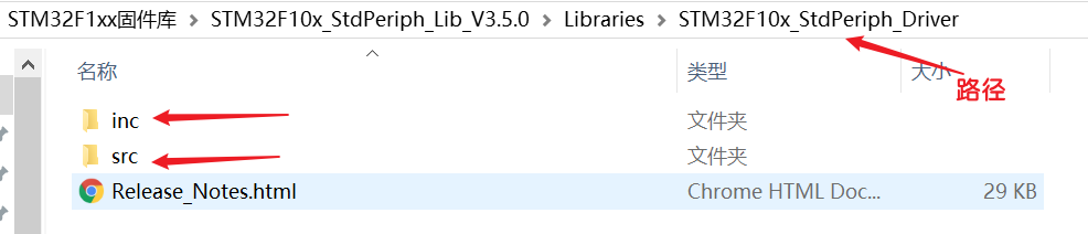
inc文件:是标准外设库函数的.h (声明) 文件。
src文件:是标准外设库函数的.c (函数实现)文件。
如何在 自己的文件夹 中使用官方的标准库
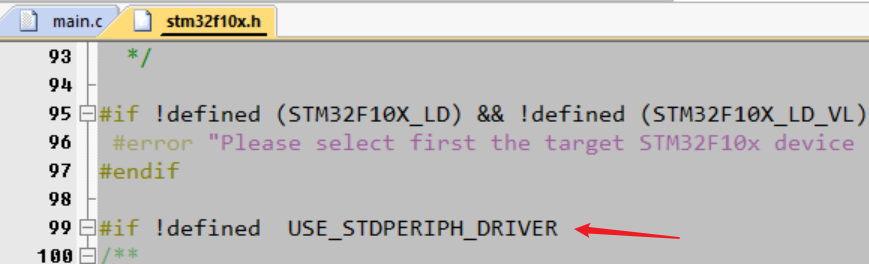
添加全局宏定义
stm32f10x_conf.h:是用户使用“标准库”时,可以不用自己包含对应的“标准库文件”,会自动为你包含。打开后可以看到:
Uncomment/Comment the line below to enable/disable peripheral header file inclusion翻译:取消注释/注释下面的行以启用/禁用外围头文件包含。
优缺点
优点:方便编程,方便 控制 “ STM32上的片上外设”
//感受一下,给人一种就算不会寄存器,都会使用 片上外设
	RCC_APB2PeriphClockCmd(RCC_APB2Periph_GPIOB | RCC_APB2Periph_GPIOE, ENABLE);
	//配置模式
	GPIO_InitTypeDef GPIO_InitStruct;		//定义结构体变量
	GPIO_InitStruct.GPIO_Pin = LED0_PIN;
	GPIO_InitStruct.GPIO_Speed = GPIO_Speed_50MHz;
	GPIO_InitStruct.GPIO_Mode = GPIO_Mode_Out_PP;
	GPIO_Init(LED0_PORT, &GPIO_InitStruct);
缺点:执行效率没有 “直接操作寄存器” 快,主要原因在于库函数中使用了大量的判断操作。
//库函数归根到底还是 操作寄存器,就是添加了很多的参数判断,
//判断传入的参数的正确性和对不同的参数进行的不同的操作
void GPIO_Init(GPIO_TypeDef* GPIOx, GPIO_InitTypeDef* GPIO_InitStruct)
{
  uint32_t currentmode = 0x00, currentpin = 0x00, pinpos = 0x00, pos = 0x00;
  uint32_t tmpreg = 0x00, pinmask = 0x00;
  /* Check the parameters */
  assert_param(IS_GPIO_ALL_PERIPH(GPIOx));
  assert_param(IS_GPIO_MODE(GPIO_InitStruct->GPIO_Mode));
  assert_param(IS_GPIO_PIN(GPIO_InitStruct->GPIO_Pin));

/*---------------------------- GPIO Mode Configuration -----------------------*/
  currentmode = ((uint32_t)GPIO_InitStruct->GPIO_Mode) & ((uint32_t)0x0F);
  if ((((uint32_t)GPIO_InitStruct->GPIO_Mode) & ((uint32_t)0x10)) != 0x00)
  {
    /* Check the parameters */
    assert_param(IS_GPIO_SPEED(GPIO_InitStruct->GPIO_Speed));
    /* Output mode */
    currentmode |= (uint32_t)GPIO_InitStruct->GPIO_Speed;
  }
/*---------------------------- GPIO CRL Configuration ------------------------*/
  /* Configure the eight low port pins */
  if (((uint32_t)GPIO_InitStruct->GPIO_Pin & ((uint32_t)0x00FF)) != 0x00)
  {
    tmpreg = GPIOx->CRL;
    for (pinpos = 0x00; pinpos < 0x08; pinpos++)
    {
      pos = ((uint32_t)0x01) << pinpos;
      /* Get the port pins position */
      currentpin = (GPIO_InitStruct->GPIO_Pin) & pos;
      if (currentpin == pos)
      {
        pos = pinpos << 2;
        /* Clear the corresponding low control register bits */
        pinmask = ((uint32_t)0x0F) << pos;
        tmpreg &= ~pinmask;
        /* Write the mode configuration in the corresponding bits */
        tmpreg |= (currentmode << pos);
        /* Reset the corresponding ODR bit */
        if (GPIO_InitStruct->GPIO_Mode == GPIO_Mode_IPD)
        {
          GPIOx->BRR = (((uint32_t)0x01) << pinpos);
        }
        else
        {
          /* Set the corresponding ODR bit */
          if (GPIO_InitStruct->GPIO_Mode == GPIO_Mode_IPU)
          {
            GPIOx->BSRR = (((uint32_t)0x01) << pinpos);
          }
        }
      }
    }
    GPIOx->CRL = tmpreg;
  }
    .......
代码编写
//宏定义,如果说不知道怎么宏定义,我可以先将函数写出来,在看看什么东西是需要更改的
#define LED0_CLK			RCC_APB2Periph_GPIOB
#define LED1_CLK			RCC_APB2Periph_GPIOE

#define LED0_PORT 			GPIOB
#define LED0_PIN			GPIO_Pin_5
#define LED1_PORT 			GPIOE
#define LED1_PIN			GPIO_Pin_5

#define Led_Off(port, pin)				( GPIO_SetBits(port, pin) 	)
#define Led_On(port, pin)				( GPIO_ResetBits(port, pin) )
#define Led_Toggle(port, pin)			( port->ODR ^= pin )	//需要位状态反转,此时的pin是GPIO_Pin_5,正好是 “对应位被置1” 的情况,直接 “ ^= ”,就可以得到想要的位状态反转
//使用库函数,用寄存器对IO管脚的操作,就不需要左移位了。(对寄存器的操作就是对地址的操作)
	RCC_APB2PeriphClockCmd(RCC_APB2Periph_GPIOB | RCC_APB2Periph_GPIOE, ENABLE);
	//配置模式
	GPIO_InitTypeDef GPIO_InitStruct;		//定义结构体变量,不要定义一个空的结构体指针,结构体变量就是一个实体,不是说传递指针,就一定要定义一个指针,可以定义一个变量,取地址就是对应的指针。
	GPIO_InitStruct.GPIO_Pin = LED0_PIN;
	GPIO_InitStruct.GPIO_Speed = GPIO_Speed_50MHz;
	GPIO_InitStruct.GPIO_Mode = GPIO_Mode_Out_PP;
	GPIO_Init(LED0_PORT, &GPIO_InitStruct);
	GPIO_InitStruct.GPIO_Pin = LED1_PIN;	//结构体变量的成员变量 只有 管脚对应的成员 发生了改变
	GPIO_Init(LED1_PORT, &GPIO_InitStruct);
	//灭灯
	Led_Off(LED0_PORT, LED0_PIN);
	Led_Off(LED1_PORT, LED1_PIN);
"我经常有那种感觉,如果这个事情来了,你却没有勇敢地去解决掉,它一定会再来。生活真是这样,它会一次次地让你去做这个功课直到你学会为止。" --《像我这样笨拙地生活》

 浙公网安备 33010602011771号