HCNA Routing&Switching之静态路由
回顾:在网络通信中,两个路由器要想通信,前提是必须有通往对端的路由;可以说路由是网络通信的基础条件;路由有很多种类,不同种类的路由信息其特点,优缺点各不相同;最为简单的就是直连路由,生成直连路由的必须满足两个条件,第一对应接口必须配置ip地址,其次对应接口物理和协议必须处于up状态;优点是自动生成,管理员只需要把对应接口配置上相应的地址,连上网线,对应直连路由就可以生成;缺点:只能够到达路由器直连的网络,不能够到达非直连的网络;
实验:如下图,配置好各设备的接口ip地址以后,看看对应路由表的变化,看看pc5,pc7以及R1是否能够ping同pc6?
分析:要想pc5,pc7和R1和pc6通信,首先R1要有去往pc6的路由,其次pc5和pc7的网关指向R1,因为pc6和pc5pc7不在同一网络(不在同一网络的设备通信,默认将数据包发送给网关);
未配置R1各接口ip地址前的路由表
|
1
2
3
4
5
6
7
8
9
10
11
12
13
14
15
16
17
18
19
20
21
22
23
24
25
26
27
28
29
30
|
<Huawei>dis ip int b*down: administratively down^down: standby(l): loopback(s): spoofingThe number of interface that is UP in Physical is 4The number of interface that is DOWN in Physical is 0The number of interface that is UP in Protocol is 1The number of interface that is DOWN in Protocol is 3Interface IP Address/Mask Physical Protocol GigabitEthernet0/0/0 unassigned up down GigabitEthernet0/0/1 unassigned up down GigabitEthernet0/0/2 unassigned up down NULL0 unassigned up up(s) <Huawei>dis ip rou<Huawei>dis ip routing-tableRoute Flags: R - relay, D - download to fib------------------------------------------------------------------------------Routing Tables: Public Destinations : 4 Routes : 4 Destination/Mask Proto Pre Cost Flags NextHop Interface 127.0.0.0/8 Direct 0 0 D 127.0.0.1 InLoopBack0 127.0.0.1/32 Direct 0 0 D 127.0.0.1 InLoopBack0127.255.255.255/32 Direct 0 0 D 127.0.0.1 InLoopBack0255.255.255.255/32 Direct 0 0 D 127.0.0.1 InLoopBack0<Huawei> |
提示:可以看到在未配置接口ip地址前,查看路由表,路由表中只有回环接口的路由信息;查看接口简要信息也可以发现对应接口的物理状态是up的,协议状态是down,不满足生成直连路由的条件,所以路由表没有对应接口的路由信息;
配置R1
|
1
2
3
4
5
6
7
8
9
10
11
12
13
14
15
16
17
18
19
20
21
22
23
24
25
26
27
28
29
30
31
32
33
34
35
36
37
38
39
40
41
42
43
44
45
46
47
48
49
50
51
52
53
|
<Huawei>sysEnter system view, return user view with Ctrl+Z.[Huawei]sys R1[R1]int g0/0/0[R1-GigabitEthernet0/0/0]ip add 10.0.0.254 24Jul 2 2021 23:00:05-08:00 R1 %%01IFNET/4/LINK_STATE(l)[0]:The line protocol IP on the interface GigabitEthernet0/0/0 has entered the UP state. int g0/0/1[R1-GigabitEthernet0/0/0][R1-GigabitEthernet0/0/1]ip add 11.0.0.254 24[R1-GigabitEthernet0/0/1]int g0/0/2[R1-GigabitEthernet0/0/2]ip add 12.0.0.1 24Jul 2 2021 23:00:05-08:00 R1 %%01IFNET/4/LINK_STATE(l)[1]:The line protocol IP on the interface GigabitEthernet0/0/1 has entered the UP state.[R1-GigabitEthernet0/0/2]ip add 12.0.0.1 24Jul 2 2021 23:00:07-08:00 R1 %%01IFNET/4/LINK_STATE(l)[2]:The line protocol IP on the interface GigabitEthernet0/0/2 has entered the UP state.[R1-GigabitEthernet0/0/2]q[R1]dis ip int b*down: administratively down^down: standby(l): loopback(s): spoofingThe number of interface that is UP in Physical is 4The number of interface that is DOWN in Physical is 0The number of interface that is UP in Protocol is 4The number of interface that is DOWN in Protocol is 0Interface IP Address/Mask Physical Protocol GigabitEthernet0/0/0 10.0.0.254/24 up up GigabitEthernet0/0/1 11.0.0.254/24 up up GigabitEthernet0/0/2 12.0.0.1/24 up up NULL0 unassigned up up(s) [R1]dis ip rou[R1]dis ip routing-tableRoute Flags: R - relay, D - download to fib------------------------------------------------------------------------------Routing Tables: Public Destinations : 13 Routes : 13 Destination/Mask Proto Pre Cost Flags NextHop Interface 10.0.0.0/24 Direct 0 0 D 10.0.0.254 GigabitEthernet0/0/0 10.0.0.254/32 Direct 0 0 D 127.0.0.1 GigabitEthernet0/0/0 10.0.0.255/32 Direct 0 0 D 127.0.0.1 GigabitEthernet0/0/0 11.0.0.0/24 Direct 0 0 D 11.0.0.254 GigabitEthernet0/0/1 11.0.0.254/32 Direct 0 0 D 127.0.0.1 GigabitEthernet0/0/1 11.0.0.255/32 Direct 0 0 D 127.0.0.1 GigabitEthernet0/0/1 12.0.0.0/24 Direct 0 0 D 12.0.0.1 GigabitEthernet0/0/2 12.0.0.1/32 Direct 0 0 D 127.0.0.1 GigabitEthernet0/0/2 12.0.0.255/32 Direct 0 0 D 127.0.0.1 GigabitEthernet0/0/2 127.0.0.0/8 Direct 0 0 D 127.0.0.1 InLoopBack0 127.0.0.1/32 Direct 0 0 D 127.0.0.1 InLoopBack0127.255.255.255/32 Direct 0 0 D 127.0.0.1 InLoopBack0255.255.255.255/32 Direct 0 0 D 127.0.0.1 InLoopBack0[R1] |
提示:可以看到在r1上的各接口上正确的配置上ip地址信息以后,对应接口的协议状态就从down转变为up状态,同时路由表中也多了对应网络的路由信息;
配置R2
|
1
2
3
4
5
6
7
8
9
10
11
12
13
14
15
16
17
18
19
20
21
22
23
24
25
26
27
28
29
30
31
32
33
34
35
36
37
38
39
40
41
42
43
44
45
46
47
|
<Huawei>sysEnter system view, return user view with Ctrl+Z.[Huawei]sys R2[R2]int g0/0/0[R2-GigabitEthernet0/0/0]ip add 12.0.0.2 24[R2-GigabitEthernet0/0/0]int g0/0/1Jul 2 2021 23:05:39-08:00 R2 %%01IFNET/4/LINK_STATE(l)[2]:The line protocol IP on the interface GigabitEthernet0/0/0 has entered the UP state.[R2-GigabitEthernet0/0/0]int g0/0/1[R2-GigabitEthernet0/0/1]ip add 22.0.0.254 24Jul 2 2021 23:05:40-08:00 R2 %%01IFNET/4/LINK_STATE(l)[3]:The line protocol IP on the interface GigabitEthernet0/0/1 has entered the UP state.[R2-GigabitEthernet0/0/1]q[R2]dis ip int b*down: administratively down^down: standby(l): loopback(s): spoofingThe number of interface that is UP in Physical is 3The number of interface that is DOWN in Physical is 1The number of interface that is UP in Protocol is 3The number of interface that is DOWN in Protocol is 1Interface IP Address/Mask Physical Protocol GigabitEthernet0/0/0 12.0.0.2/24 up up GigabitEthernet0/0/1 22.0.0.254/24 up up GigabitEthernet0/0/2 unassigned down down NULL0 unassigned up up(s) [R2]dis ip rout[R2]dis ip routing-tableRoute Flags: R - relay, D - download to fib------------------------------------------------------------------------------Routing Tables: Public Destinations : 10 Routes : 10 Destination/Mask Proto Pre Cost Flags NextHop Interface 12.0.0.0/24 Direct 0 0 D 12.0.0.2 GigabitEthernet0/0/0 12.0.0.2/32 Direct 0 0 D 127.0.0.1 GigabitEthernet0/0/0 12.0.0.255/32 Direct 0 0 D 127.0.0.1 GigabitEthernet0/0/0 22.0.0.0/24 Direct 0 0 D 22.0.0.254 GigabitEthernet0/0/1 22.0.0.254/32 Direct 0 0 D 127.0.0.1 GigabitEthernet0/0/1 22.0.0.255/32 Direct 0 0 D 127.0.0.1 GigabitEthernet0/0/1 127.0.0.0/8 Direct 0 0 D 127.0.0.1 InLoopBack0 127.0.0.1/32 Direct 0 0 D 127.0.0.1 InLoopBack0127.255.255.255/32 Direct 0 0 D 127.0.0.1 InLoopBack0255.255.255.255/32 Direct 0 0 D 127.0.0.1 InLoopBack0[R2] |
提示:按照题意我们配置好了两个路由器的名称和相关接口的ip地址,对应路由器各自都生成了相应的直连路由;
配置好各pc的ip地址信息,然后用pc5ping pc6看看是否可以正常通信?
配置pc5

提示:pc5和R1的g0/0/0口是直连,所以对应pc5的网关必须指向R1的g0/0/0接口的ip地址;
配置pc6

提示:pc6和R2的g0/0/1口是直连,所以对应pc6的网关必须指向R2的g0/0/1接口的ip地址;
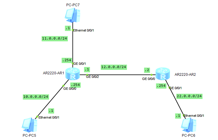
配置pc7
提示:pc7和R1的g0/0/1口是直连,所以对应pc7的网关必须指向R1的g0/0/1接口的ip地址;
验证:pc5 ping pc6看看是否可以通信?
|
1
2
3
4
5
6
7
8
9
10
11
12
13
14
15
16
17
18
19
20
21
22
23
24
25
26
|
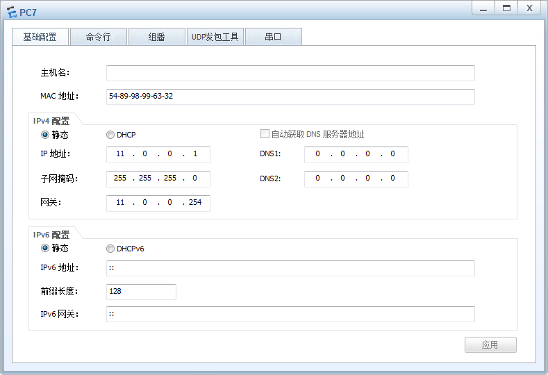
PC>ipconfigLink local IPv6 address...........: fe80::5689:98ff:fe54:5adcIPv6 address......................: :: / 128IPv6 gateway......................: ::IPv4 address......................: 10.0.0.1Subnet mask.......................: 255.255.255.0Gateway...........................: 10.0.0.254Physical address..................: 54-89-98-54-5A-DCDNS server........................:PC>ping 22.0.0.1Ping 22.0.0.1: 32 data bytes, Press Ctrl_C to breakRequest timeout!Request timeout!Request timeout!Request timeout!Request timeout!--- 22.0.0.1 ping statistics --- 5 packet(s) transmitted 0 packet(s) received 100.00% packet lossPC> |
提示:可以看到在pc5上ping pc6,给我们的回馈是请求超时;
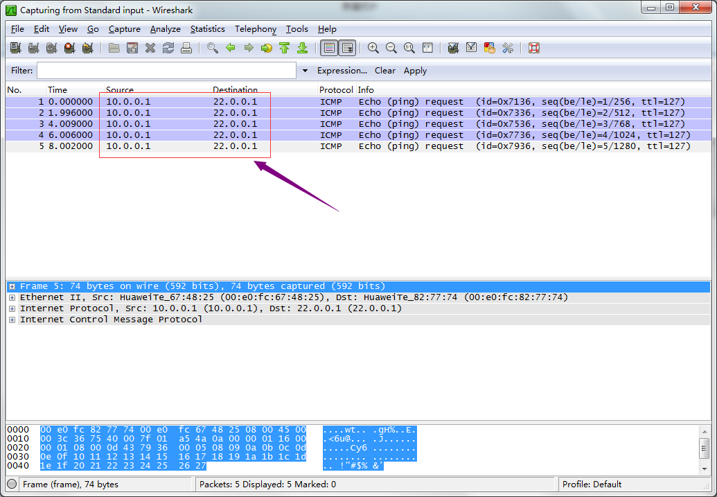
在r1的g0/0/2口抓包,看看对应是否有数据包通过?
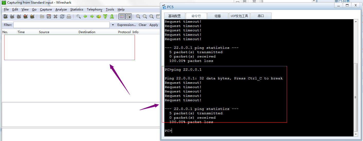
提示:可以看到在R1的g0/0/2口上没有抓到任何数据包,说明ping22.0.0.1的数据包没有在r1和r2直连链路上通过,所以我们ping pc6回馈给我们的是请求超时,其原因是R1上没有去往pc6的路由,当R1收到pc5发来的数据包,查看对应数据包是去往22.0.0.1的,R1在自己的路由表中没有匹配到去往22.0.0.1的路由,所以R1直接将对应数据包丢弃,不予转发;
验证:用pc5 ping pc7 看看是否能够正常通信?
|
1
2
3
4
5
6
7
8
9
10
11
12
13
14
15
16
17
18
19
20
21
22
23
24
25
26
27
|
PC>ipconfigLink local IPv6 address...........: fe80::5689:98ff:fe54:5adcIPv6 address......................: :: / 128IPv6 gateway......................: ::IPv4 address......................: 10.0.0.1Subnet mask.......................: 255.255.255.0Gateway...........................: 10.0.0.254Physical address..................: 54-89-98-54-5A-DCDNS server........................:PC>ping 11.0.0.1Ping 11.0.0.1: 32 data bytes, Press Ctrl_C to breakRequest timeout!From 11.0.0.1: bytes=32 seq=2 ttl=127 time=16 msFrom 11.0.0.1: bytes=32 seq=3 ttl=127 time=16 msFrom 11.0.0.1: bytes=32 seq=4 ttl=127 time=16 msFrom 11.0.0.1: bytes=32 seq=5 ttl=127 time<1 ms--- 11.0.0.1 ping statistics --- 5 packet(s) transmitted 4 packet(s) received 20.00% packet loss round-trip min/avg/max = 0/12/16 msPC> |
提示:可以看到pc5 是可以正常和pc7通信;其实原因很简单,就是因为R1上有对应去往pc7和pc5的直连路由,所以pc5和pc7可以正常通信;通过上述实验,可以看到直连路由的优点是它自动生成,只要管理员正确配置了ip地址,并且在接口上接上了线,对应直连路由就会自动生成了;缺点就是不能和非直连的网络通信;这样一来我们要想和非直连网络通信,光凭直连路由是做不到;
静态路由
所谓静态路由就是指管理员人工手动添加的路由信息;
添加静态路由的命令语法
|
1
|
ip route-static 目标网络 子网掩码/前缀 下一跳地址/出接口 |
提示:如果出接口为以太网接口,则必须要指定下一跳地址,如果出接口为串口,可以使用下一跳或出接口来配置;
实验:还是上面的top,实现pc5能够ping 通pc6
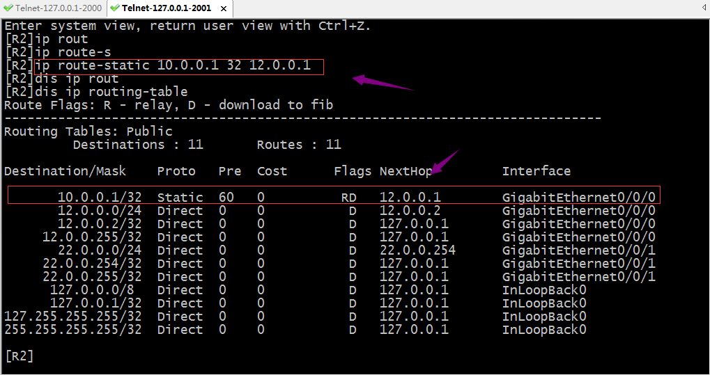
在R1上添加静态路由
验证:现在R1上有去往pc6的路由信息,用pc 5ping pc6 看看是否可以正常通信?
|
1
2
3
4
5
6
7
8
9
10
11
12
13
14
15
16
17
18
19
20
21
22
23
24
25
26
|
PC>ipconfigLink local IPv6 address...........: fe80::5689:98ff:fe54:5adcIPv6 address......................: :: / 128IPv6 gateway......................: ::IPv4 address......................: 10.0.0.1Subnet mask.......................: 255.255.255.0Gateway...........................: 10.0.0.254Physical address..................: 54-89-98-54-5A-DCDNS server........................:PC>ping 22.0.0.1Ping 22.0.0.1: 32 data bytes, Press Ctrl_C to breakRequest timeout!Request timeout!Request timeout!Request timeout!Request timeout!--- 22.0.0.1 ping statistics --- 5 packet(s) transmitted 0 packet(s) received 100.00% packet lossPC> |
提示:可以看到pc5现在依然ping 不通pc6;
在r1的g0/0/2口抓包,看看是否有对应数据包通过?
提示:现在在R1的g0/0/2口可以抓到pc5 ping pc 6的包,但是没有pc6 回来的包,其原因是R2上没有到达pc5所在网络的路由;所以pc5 ping 不同pc6;
在R2上添加去往pc5的路由
验证:现在用pc5再次ping pc6看看是否能通?
|
1
2
3
4
5
6
7
8
9
10
11
12
13
14
15
16
17
18
19
20
21
22
23
24
25
26
27
|
PC>ipconfigLink local IPv6 address...........: fe80::5689:98ff:fe54:5adcIPv6 address......................: :: / 128IPv6 gateway......................: ::IPv4 address......................: 10.0.0.1Subnet mask.......................: 255.255.255.0Gateway...........................: 10.0.0.254Physical address..................: 54-89-98-54-5A-DCDNS server........................:PC>ping 22.0.0.1Ping 22.0.0.1: 32 data bytes, Press Ctrl_C to breakRequest timeout!From 22.0.0.1: bytes=32 seq=2 ttl=126 time=16 msFrom 22.0.0.1: bytes=32 seq=3 ttl=126 time=16 msFrom 22.0.0.1: bytes=32 seq=4 ttl=126 time=16 msFrom 22.0.0.1: bytes=32 seq=5 ttl=126 time=16 ms--- 22.0.0.1 ping statistics --- 5 packet(s) transmitted 4 packet(s) received 20.00% packet loss round-trip min/avg/max = 0/16/16 msPC> |
提示:可以看到pc5可以正常ping 通pc6了;
验证:在R1的g0/0/2口抓包,看看对应数据包是否有回复了?
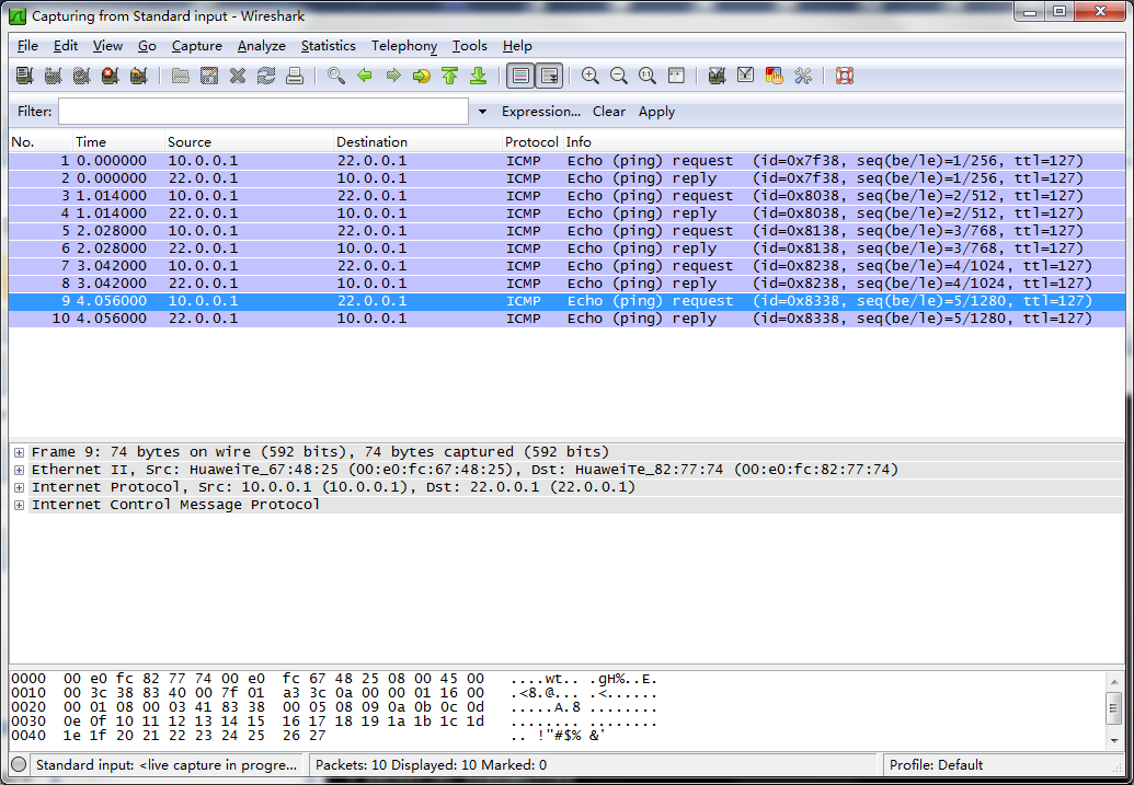
提示:可以看到现在在R1的g0/0/2口抓包就有正常回复包;
验证:pc7 ping pc6,看看是否能够ping通?
|
1
2
3
4
5
6
7
8
9
10
11
12
13
14
15
16
17
18
19
20
21
22
23
24
25
26
|
PC>ipconfigLink local IPv6 address...........: fe80::5689:98ff:fe99:6332IPv6 address......................: :: / 128IPv6 gateway......................: ::IPv4 address......................: 11.0.0.1Subnet mask.......................: 255.255.255.0Gateway...........................: 11.0.0.254Physical address..................: 54-89-98-99-63-32DNS server........................:PC>ping 22.0.0.1Ping 22.0.0.1: 32 data bytes, Press Ctrl_C to breakRequest timeout!Request timeout!Request timeout!Request timeout!Request timeout!--- 22.0.0.1 ping statistics --- 5 packet(s) transmitted 0 packet(s) received 100.00% packet lossPC> |
提示:可以看到pc7到现在依然无法Ping通pc6,其原因是r2没有回来pc7的路由,所以pc7现在能够把包送达到pc6,但回不来,所以导致pc7ping不同pc6;要想实现pc7ping通pc6,我们还需要在r2上添加一条去往pc7的路由;
在R2上添加去往pc7的路由
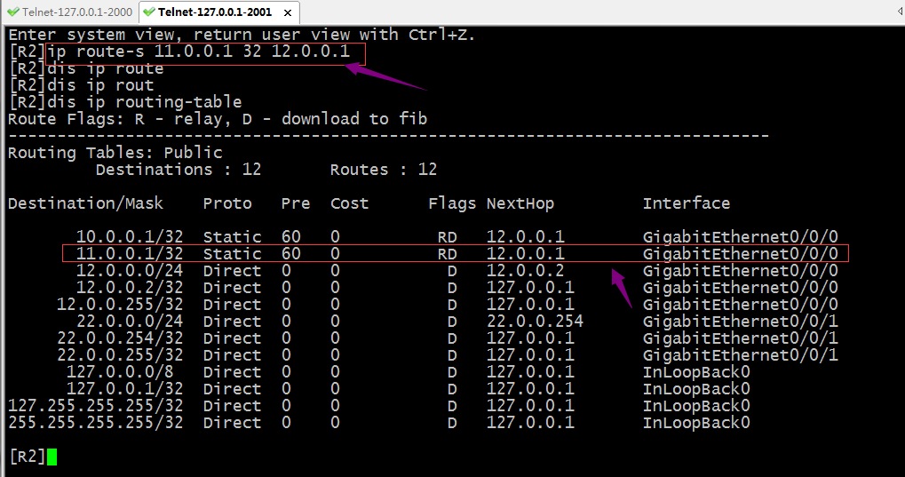
验证:现在pc7 ping pc6,看看是否可以正常通信?
|
1
2
3
4
5
6
7
8
9
10
11
12
13
14
15
16
17
18
19
20
21
22
23
24
25
26
27
|
PC>ipconfigLink local IPv6 address...........: fe80::5689:98ff:fe99:6332IPv6 address......................: :: / 128IPv6 gateway......................: ::IPv4 address......................: 11.0.0.1Subnet mask.......................: 255.255.255.0Gateway...........................: 11.0.0.254Physical address..................: 54-89-98-99-63-32DNS server........................:PC>ping 22.0.0.1Ping 22.0.0.1: 32 data bytes, Press Ctrl_C to breakFrom 22.0.0.1: bytes=32 seq=1 ttl=126 time=16 msFrom 22.0.0.1: bytes=32 seq=2 ttl=126 time=16 msFrom 22.0.0.1: bytes=32 seq=3 ttl=126 time=16 msFrom 22.0.0.1: bytes=32 seq=4 ttl=126 time=16 msFrom 22.0.0.1: bytes=32 seq=5 ttl=126 time=16 ms--- 22.0.0.1 ping statistics --- 5 packet(s) transmitted 5 packet(s) received 0.00% packet loss round-trip min/avg/max = 16/16/16 msPC> |
提示:可以看到pc7现在也能正常ping通pc6;通过上述实验我们发现静态路由的配置还是很简单,必须手动指定目标网络,掩码以及下一跳;其次网络通信的过程是是双向的,配置静态路由,我们必须考虑来回的路由在所经过的路由器都要有对应的路由;如果网络规模非常大(网段特别多,路由器特别多),如果用手动配置静态路由的方式,就不是很容易了;所以静态路由适用于网络规模不是太大的环境中;除此之外静态路由有一个非常大的缺点,它不能根据top变化而变化,这样一来,如果现网中某个接口地址的发生变化,管理员必须手动更改路由信息;
负载分担
负载分担就是等价路由即到达同一目标网络的路由有多条,并且他们的优先级开销都一样;
实验:如下图,配置pc5和pc6通信的流量都可以走R1,R2之间的两条链路
在R1的g0/0/1接口上配置对应的ip地址,并配置访问pc6的对应路由信息
|
1
2
3
4
5
6
7
8
9
10
11
12
13
14
15
16
17
18
19
20
21
22
23
24
25
26
27
28
29
30
31
32
|
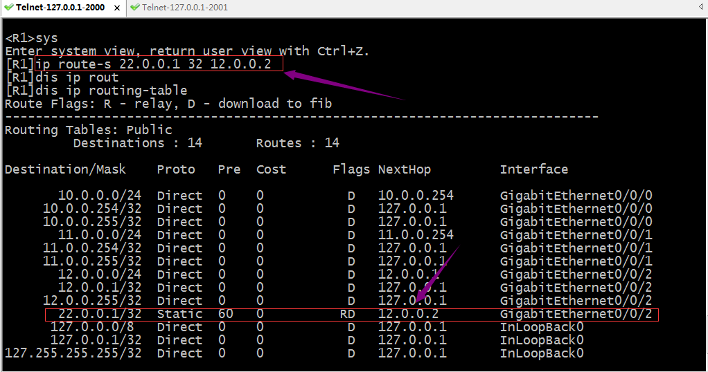
<R1>sysEnter system view, return user view with Ctrl+Z.[R1]int g0/0/1[R1-GigabitEthernet0/0/1]ip add 21.0.0.1 24[R1-GigabitEthernet0/0/1]q[R1]ip route-s 22.0.0.1 32 21.0.0.2[R1]dis ip routin[R1]dis ip routing-tableRoute Flags: R - relay, D - download to fib------------------------------------------------------------------------------Routing Tables: Public Destinations : 14 Routes : 15 Destination/Mask Proto Pre Cost Flags NextHop Interface 10.0.0.0/24 Direct 0 0 D 10.0.0.254 GigabitEthernet0/0/0 10.0.0.254/32 Direct 0 0 D 127.0.0.1 GigabitEthernet0/0/0 10.0.0.255/32 Direct 0 0 D 127.0.0.1 GigabitEthernet0/0/0 12.0.0.0/24 Direct 0 0 D 12.0.0.1 GigabitEthernet0/0/2 12.0.0.1/32 Direct 0 0 D 127.0.0.1 GigabitEthernet0/0/2 12.0.0.255/32 Direct 0 0 D 127.0.0.1 GigabitEthernet0/0/2 21.0.0.0/24 Direct 0 0 D 21.0.0.1 GigabitEthernet0/0/1 21.0.0.1/32 Direct 0 0 D 127.0.0.1 GigabitEthernet0/0/1 21.0.0.255/32 Direct 0 0 D 127.0.0.1 GigabitEthernet0/0/1 22.0.0.1/32 Static 60 0 RD 12.0.0.2 GigabitEthernet0/0/2 Static 60 0 RD 21.0.0.2 GigabitEthernet0/0/1 127.0.0.0/8 Direct 0 0 D 127.0.0.1 InLoopBack0 127.0.0.1/32 Direct 0 0 D 127.0.0.1 InLoopBack0127.255.255.255/32 Direct 0 0 D 127.0.0.1 InLoopBack0255.255.255.255/32 Direct 0 0 D 127.0.0.1 InLoopBack0[R1] |
在R2的g0/0/2接口上配置对应的ip地址,并配置访问pc5的对应路由信息
|
1
2
3
4
5
6
7
8
9
10
11
12
13
14
15
16
17
18
19
20
21
22
23
24
25
26
27
28
29
30
31
32
33
34
|
<R2>sysEnter system view, return user view with Ctrl+Z.[R2]int g0/0/2[R2-GigabitEthernet0/0/2]ip add 21.0.0.2 24Jul 3 2021 00:34:04-08:00 R2 %%01IFNET/4/LINK_STATE(l)[0]:The line protocol IP on the interface GigabitEthernet0/0/2 has entered the UP state.[R2-GigabitEthernet0/0/2]q[R2]ip route-s 10.0.0.1 32 21.0.0.1[R2]dis ip routing[R2]dis ip routing-tableRoute Flags: R - relay, D - download to fib------------------------------------------------------------------------------Routing Tables: Public Destinations : 15 Routes : 16 Destination/Mask Proto Pre Cost Flags NextHop Interface 10.0.0.1/32 Static 60 0 RD 12.0.0.1 GigabitEthernet0/0/0 Static 60 0 RD 21.0.0.1 GigabitEthernet0/0/2 11.0.0.1/32 Static 60 0 RD 12.0.0.1 GigabitEthernet0/0/0 12.0.0.0/24 Direct 0 0 D 12.0.0.2 GigabitEthernet0/0/0 12.0.0.2/32 Direct 0 0 D 127.0.0.1 GigabitEthernet0/0/0 12.0.0.255/32 Direct 0 0 D 127.0.0.1 GigabitEthernet0/0/0 21.0.0.0/24 Direct 0 0 D 21.0.0.2 GigabitEthernet0/0/2 21.0.0.2/32 Direct 0 0 D 127.0.0.1 GigabitEthernet0/0/2 21.0.0.255/32 Direct 0 0 D 127.0.0.1 GigabitEthernet0/0/2 22.0.0.0/24 Direct 0 0 D 22.0.0.254 GigabitEthernet0/0/1 22.0.0.254/32 Direct 0 0 D 127.0.0.1 GigabitEthernet0/0/1 22.0.0.255/32 Direct 0 0 D 127.0.0.1 GigabitEthernet0/0/1 127.0.0.0/8 Direct 0 0 D 127.0.0.1 InLoopBack0 127.0.0.1/32 Direct 0 0 D 127.0.0.1 InLoopBack0127.255.255.255/32 Direct 0 0 D 127.0.0.1 InLoopBack0255.255.255.255/32 Direct 0 0 D 127.0.0.1 InLoopBack0[R2] |
提示:这样配置以后,pc5所在网络和pc6所在网络的设备通信就有两条链路一起负载,这样可以减少之前一条链路的压力;
验证:用tracert 追踪pc5和pc6通信所走的链路

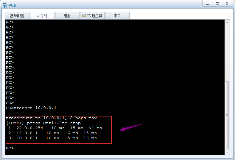
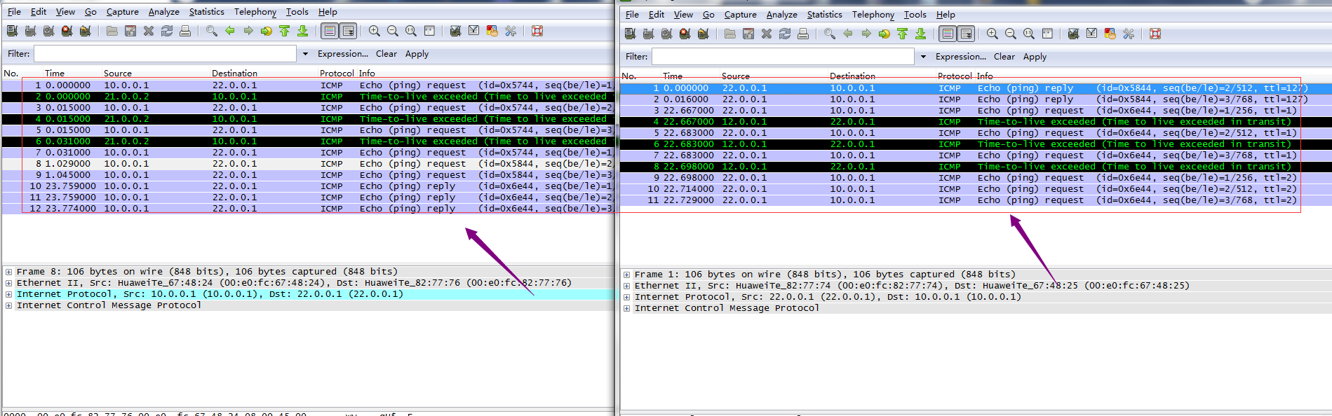
提示:从上面的链路追踪和抓包可以看到现在pc5和pc6通信,两条链路都用上了,pc5pingpc6走下面21网段,回复包全部走12网段所在链路,pc6pingpc5 去走12网段所在链路,回来走21网段所在链路;
浮动路由
浮动路由又称主备路由,即去往同一网络的多条路由中有主备之分,默认情况主路由工作(活动路由),一旦活动路由宕掉,备份路由马上就变为活动路由;一旦主路由恢复,备份路由又会处于非活动状态;有点类似keepalived的抢占模式,一旦主挂了,备份路由马上变为主,一旦原来的主活了,现在的主马上就变为备份路由;其原理就是在等价路由的基础上,借助路由器转发原则根据其优先级来确定那条路由存在路由表(最优路由),一旦存在路由表中的最优路由链路宕掉,对应接口也会随之宕掉,所以对应最优路由来说,其出接口就会变为unknow状态,导致路由不可用,此时根据路由转发原则,原来的次优路由就会变为最优路由,一旦优先级最小的路由所在链路恢复正常,路由器又会根据路由转发原则把次优路由替换下来,让其处于非活动状态;
实验:还是上述top,在R1上配置12网段所在链路为主链路,21网段为备份链路
配置r1
|
1
2
3
4
5
6
7
8
9
10
11
12
13
14
15
16
17
18
19
20
21
22
23
24
25
26
27
28
29
30
31
32
33
34
35
36
37
38
39
40
41
|
[R1]dis ip routing-table protocol staticRoute Flags: R - relay, D - download to fib------------------------------------------------------------------------------Public routing table : Static Destinations : 1 Routes : 2 Configured Routes : 2Static routing table status : <Active> Destinations : 1 Routes : 2Destination/Mask Proto Pre Cost Flags NextHop Interface 22.0.0.1/32 Static 60 0 RD 12.0.0.2 GigabitEthernet0/0/2 Static 60 0 RD 21.0.0.2 GigabitEthernet0/0/1Static routing table status : <Inactive> Destinations : 0 Routes : 0[R1]ip rou [R1]ip route-s 22.0.0.1 32 21.0.0.2 pre 61Info: Succeeded in modifying route.[R1]dis ip routing-table protocol static Route Flags: R - relay, D - download to fib------------------------------------------------------------------------------Public routing table : Static Destinations : 1 Routes : 2 Configured Routes : 2Static routing table status : <Active> Destinations : 1 Routes : 1Destination/Mask Proto Pre Cost Flags NextHop Interface 22.0.0.1/32 Static 60 0 RD 12.0.0.2 GigabitEthernet0/0/2Static routing table status : <Inactive> Destinations : 1 Routes : 1Destination/Mask Proto Pre Cost Flags NextHop Interface 22.0.0.1/32 Static 61 0 R 21.0.0.2 GigabitEthernet0/0/1[R1] |
提示:在R1上修改原有去往22.0.0.1 下一跳为21.0.0.2 的路由的优先级为61,此时对应路由器来说,去往22.0.0.1的两条路由就不再是等价路由,所以下一跳为12.0.0.2的路由就会被选为最优路由,下一跳为21.0.0.2的路由就会被选为次优非活动路由;这里需要提醒的是以上路由只是针对r1,对r2来说,它的路由还是等价路由,并不会改变;
配置R2,12网段所在链路为备份链路,21网段为主链路
|
1
2
3
4
5
6
7
8
9
10
11
12
13
14
15
16
17
18
19
20
21
22
23
24
25
26
27
28
29
30
31
32
33
34
35
36
37
38
39
40
41
42
|
[R2]dis ip routing-table protocol staticRoute Flags: R - relay, D - download to fib------------------------------------------------------------------------------Public routing table : Static Destinations : 2 Routes : 3 Configured Routes : 3Static routing table status : <Active> Destinations : 2 Routes : 3Destination/Mask Proto Pre Cost Flags NextHop Interface 10.0.0.1/32 Static 60 0 RD 12.0.0.1 GigabitEthernet0/0/0 Static 60 0 RD 21.0.0.1 GigabitEthernet0/0/2 11.0.0.1/32 Static 60 0 RD 12.0.0.1 GigabitEthernet0/0/0Static routing table status : <Inactive> Destinations : 0 Routes : 0[R2]ip route-s 10.0.0.1 32 12.0.0.1 pre 61Info: Succeeded in modifying route.[R2]dis ip routing-table protocol static Route Flags: R - relay, D - download to fib------------------------------------------------------------------------------Public routing table : Static Destinations : 2 Routes : 3 Configured Routes : 3Static routing table status : <Active> Destinations : 2 Routes : 2Destination/Mask Proto Pre Cost Flags NextHop Interface 10.0.0.1/32 Static 60 0 RD 21.0.0.1 GigabitEthernet0/0/2 11.0.0.1/32 Static 60 0 RD 12.0.0.1 GigabitEthernet0/0/0Static routing table status : <Inactive> Destinations : 1 Routes : 1Destination/Mask Proto Pre Cost Flags NextHop Interface 10.0.0.1/32 Static 61 0 R 12.0.0.1 GigabitEthernet0/0/0[R2] |
验证:在R1上把12网段所在接口宕掉,看看对应的备份路由是否会成为活动路由?
|
1
2
3
4
5
6
7
8
9
10
11
12
13
14
15
16
17
18
19
20
21
22
23
24
25
26
27
28
29
30
31
32
33
34
35
36
37
38
39
40
41
42
43
44
45
|
<R1>sysEnter system view, return user view with Ctrl+Z.[R1]dis ip int b*down: administratively down^down: standby(l): loopback(s): spoofingThe number of interface that is UP in Physical is 4The number of interface that is DOWN in Physical is 0The number of interface that is UP in Protocol is 4The number of interface that is DOWN in Protocol is 0Interface IP Address/Mask Physical Protocol GigabitEthernet0/0/0 10.0.0.254/24 up up GigabitEthernet0/0/1 21.0.0.1/24 up up GigabitEthernet0/0/2 12.0.0.1/24 up up NULL0 unassigned up up(s) [R1]int g0/0/2[R1-GigabitEthernet0/0/2]shutdowJul 3 2021 01:22:12-08:00 R1 %%01IFPDT/4/IF_STATE(l)[0]:Interface GigabitEthernet0/0/2 has turned into DOWN state.[R1-GigabitEthernet0/0/2][R1-GigabitEthernet0/0/2]Jul 3 2021 01:22:13-08:00 R1 %%01IFNET/4/LINK_STATE(l)[1]:The line protocol IP on the interface GigabitEthernet0/0/2 has entered the DOWN state.[R1-GigabitEthernet0/0/2]q[R1]dis ip routing-table protocol staticRoute Flags: R - relay, D - download to fib------------------------------------------------------------------------------Public routing table : Static Destinations : 1 Routes : 2 Configured Routes : 2Static routing table status : <Active> Destinations : 1 Routes : 1Destination/Mask Proto Pre Cost Flags NextHop Interface 22.0.0.1/32 Static 61 0 RD 21.0.0.2 GigabitEthernet0/0/1Static routing table status : <Inactive> Destinations : 1 Routes : 1Destination/Mask Proto Pre Cost Flags NextHop Interface 22.0.0.1/32 Static 60 0 12.0.0.2 Unknown[R1] |
提示:可以看到R1上的g0/0/2接口宕掉以后,对应活动路由变成了非活动路由,原来的非活动路由变成了活动路由;当然路由的变化也意味着其数据包的走向也发生了变化,从而实现链路切换;
恢复R1上的g0/0/2接口,看看对应路由变化
|
1
2
3
4
5
6
7
8
9
10
11
12
13
14
15
16
17
18
19
20
21
22
23
24
25
26
27
|
[R1-GigabitEthernet0/0/2]undo shutdown[R1-GigabitEthernet0/0/2]Jul 3 2021 01:26:52-08:00 R1 %%01IFPDT/4/IF_STATE(l)[2]:Interface GigabitEthernet0/0/2 has turned into UP state.[R1-GigabitEthernet0/0/2]Jul 3 2021 01:26:52-08:00 R1 %%01IFNET/4/LINK_STATE(l)[3]:The line protocol IP on the interface GigabitEthernet0/0/2 has entered the UP state.[R1-GigabitEthernet0/0/2]q [R1]dis ip routing-table protocol staticRoute Flags: R - relay, D - download to fib------------------------------------------------------------------------------Public routing table : Static Destinations : 1 Routes : 2 Configured Routes : 2Static routing table status : <Active> Destinations : 1 Routes : 1Destination/Mask Proto Pre Cost Flags NextHop Interface 22.0.0.1/32 Static 60 0 RD 12.0.0.2 GigabitEthernet0/0/2Static routing table status : <Inactive> Destinations : 1 Routes : 1Destination/Mask Proto Pre Cost Flags NextHop Interface 22.0.0.1/32 Static 61 0 R 21.0.0.2 GigabitEthernet0/0/1[R1] |
提示:可以看到当接口恢复,对应活动路由又会变为非活动路由,实现了链路和路由的切换;当然对于r2也是同样的原理;从某种意义上我们可以理解浮动路由其实就是链接的高可用;
缺省路由
从上面的实验和配置过程来看,使用静态路由,必须在对应路由器上配置上数据包来回的路由,如果没有对应网段的路由,则我们就不能够正常访问对应的目标网络;这样一来我们如果要访问的网络非常多,比如互联网,我们不能也不应该把全互联网所有路由都写进路由器,即便可以,运营商和互联网的路由非常多,一般路由器也存不下,为了解决这样的问题,缺省路由就可以派上用场了;所谓缺省路由是指,在路由表中,所有未被匹配的路由,都可以被缺省路由所匹配;缺省路由以0.0.0.0为目标网络,掩码为0.0.0.0或前缀为0 来表示匹配任意目标网络;根据路由器的转发原则,掩码最长匹配优先,缺省路由的优先级是最低的,即最后才会被匹配;缺省路由的作用是减少路由条目,减轻路由器查找匹配路由的压力;通常用于末梢网络,比如家庭上网,企业出口;缺省路由可以静态配置,也可通过动态路由协议发布;
实验:静态配置缺省路由,实现pc5和pc6互通

配置R1
|
1
2
3
4
5
6
7
8
9
10
11
12
13
14
15
16
17
18
19
20
21
22
23
24
25
26
27
28
29
30
|
<Huawei>sysEnter system view, return user view with Ctrl+Z.[Huawei]sys R1[R1]int g0/0/0[R1-GigabitEthernet0/0/0]ip add 10.0.0.254 24[R1-GigabitEthernet0/0/0]int g0/0/1[R1-GigabitEthernet0/0/1]ip add 12.0.0.1 24Jul 3 2021 01:55:33-08:00 R1 %%01IFNET/4/LINK_STATE(l)[0]:The line protocol IP on the interface GigabitEthernet0/0/0 has entered the UP state.[R1-GigabitEthernet0/0/1]ip add 12.0.0.1 24[R1-GigabitEthernet0/0/1]q[R1]ip route-s 0.0.0.0 0 12.0.0.2Jul 3 2021 01:55:33-08:00 R1 %%01IFNET/4/LINK_STATE(l)[1]:The line protocol IP on the interface GigabitEthernet0/0/1 has entered the UP state.[R1]ip route-s 0.0.0.0 0 12.0.0.2[R1]dis ip routing-table pro staticRoute Flags: R - relay, D - download to fib------------------------------------------------------------------------------Public routing table : Static Destinations : 1 Routes : 1 Configured Routes : 1Static routing table status : <Active> Destinations : 1 Routes : 1Destination/Mask Proto Pre Cost Flags NextHop Interface 0.0.0.0/0 Static 60 0 RD 12.0.0.2 GigabitEthernet0/0/1Static routing table status : <Inactive> Destinations : 0 Routes : 0[R1] |
配置R2
|
1
2
3
4
5
6
7
8
9
10
11
12
13
14
15
16
17
18
19
20
21
22
23
24
25
26
27
28
29
30
|
<Huawei>sysEnter system view, return user view with Ctrl+Z.[Huawei]sys R2[R2]int g0/0/0[R2-GigabitEthernet0/0/0]ip add 12.0.0.2 24[R2-GigabitEthernet0/0/0]int g0/0/1[R2-GigabitEthernet0/0/1]ip add 22.0.0.254Jul 3 2021 01:55:45-08:00 R2 %%01IFNET/4/LINK_STATE(l)[0]:The line protocol IP on the interface GigabitEthernet0/0/0 has entered the UP state.[R2-GigabitEthernet0/0/1]ip add 22.0.0.254 24[R2-GigabitEthernet0/0/1]q[R2]ip route-s 0.0.0.0 0 12.0.0.1Jul 3 2021 01:55:45-08:00 R2 %%01IFNET/4/LINK_STATE(l)[1]:The line protocol IP on the interface GigabitEthernet0/0/1 has entered the UP state.[R2]ip route-s 0.0.0.0 0 12.0.0.1[R2]dis ip routing-table protocol staticRoute Flags: R - relay, D - download to fib------------------------------------------------------------------------------Public routing table : Static Destinations : 1 Routes : 1 Configured Routes : 1Static routing table status : <Active> Destinations : 1 Routes : 1Destination/Mask Proto Pre Cost Flags NextHop Interface 0.0.0.0/0 Static 60 0 RD 12.0.0.1 GigabitEthernet0/0/0Static routing table status : <Inactive> Destinations : 0 Routes : 0[R2] |
验证:用pc5 ping pc6 看看是否可以互通?

提示:可以看到配置缺省静态路由以后,pc5是可以正常和pc6通信;同样的原理,pc6也是可以正常和pc5通信;有了缺省路由我们只需要写一条了路由,即可匹配任意路由;这里需要提醒一下,缺省路由一般用于末梢网络,如果不是末梢网络的路由器,需要结合静态明细路由或动态路由;

 浙公网安备 33010602011771号