
HDLbits刷题笔记—Mt2015 lfsr
Description:
Taken from 2015 midterm question 5. See also the first part of this question: mt2015_muxdff
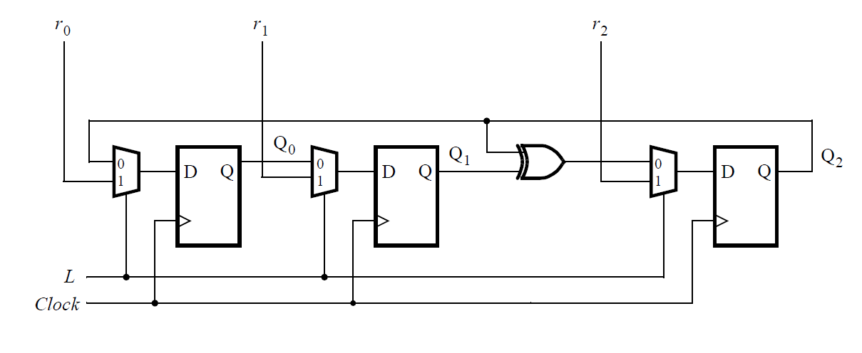
Write the Verilog code for this sequential circuit (Submodules are ok, but the top-level must be named top_module). Assume that you are going to implement the circuit on the DE1-SoC board. Connect the R inputs to the SW switches, connect Clock to KEY[0], and L to KEY[1]. Connect the Q outputs to the red lights LEDR.
module top_module (
	input [2:0] SW,      // R
	input [1:0] KEY,     // L and clk
	output [2:0] LEDR);  // Q
    sub_module s1(LEDR[2],SW[0],KEY[0],KEY[1],LEDR[0]);
    sub_module s2(LEDR[0],SW[1],KEY[0],KEY[1],LEDR[1]);
    sub_module s3(LEDR[1]^LEDR[2],SW[2],KEY[0],KEY[1],LEDR[2]);


endmodule
module sub_module(
    input q1,
    input r,
    input clk,
    input l,
    output q2);
    always@(posedge clk)begin
        case(l)
            0:q2<=q1;
            1:q2<=r;
        endcase
    end
endmodule
本文来自博客园,作者:Tao_W,转载请注明原文链接:https://www.cnblogs.com/tao1997/p/15519879.html
个人学习记录,望不吝赐教
 浙公网安备 33010602011771号