DC标准单元库内容结构(一):全局信息解释
全局信息
库属性部分
通用属性(general attribute)
technology(cmos | fpga); 工艺类型
delay_model : [ generic_cmos | table_lookup | cmos2 | piecewise_cmos | dcm]; 延迟模型:指明在计算延迟时用的那个模型
in_place_swap_mode : [match_footpoint...]; 替代交换方式
library_features(report_delay_calculate); 库特征
bus_naming_style : "Bus***..."; 总线命名方式
文档属性(documentation attribute)
revision : ***;
date : ***;
comment : ***;
单位定义(unit attribute)
time_unit : "1ns"; 时间单位
voltage_unit : "1V"; 电压单位
current_unit : "1mA"; 电流单位
pulling_resistance_unit : "1kohm"; 上下拉电阻单位
leakage_power_unit : "1pW"; 漏电功耗
capacitive_load_unit : (1.0,pf); 电容单位
环境描述
操作条件(operation conditions)
nom_process : 1;
nom_temperature : 125;
nom_voltage : 1.62;
operating_conditions(slow) {
process : 1;
temperature : 125;
voltage : 1.62;
tree_type : balanced_tree
}
default_operating_conditions : slow;
操作条件(operating_conditions)可以预先设置多组,并为每一组参数设置name(e.g. slow),使用default_operating_conditions 声明最终选择的操作条件参数
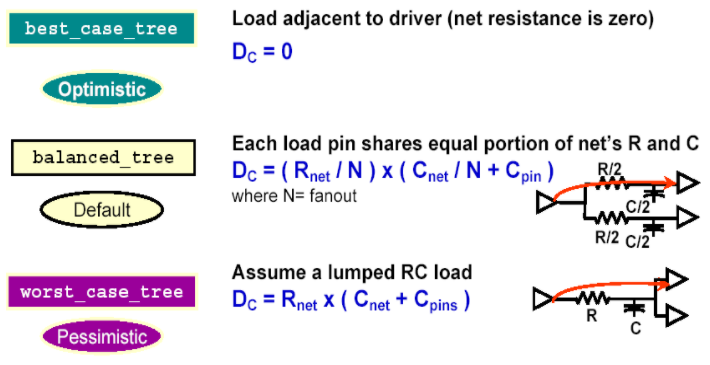
tree_type(时钟树模型)定义实际布局之前的延时计算方法,有best_case_tree、balance_tree、worst_case_tree三种模型
临界条件(threshold definitions)
slew_lower_threshold_pct_fall : 30.0; 波形下降沿高低临界值
slew_upper_threshold_pct_fall : 70.0;
slew_lower_threshold_pct_rise : 30.0; 波形上升沿高低临界值
slew_upper_threshold_pct_rise : 70.0;
input_threshold_pct_fall : 50.0; 输入上升/下降沿采样点
input_threshold_pct_rise : 50.0;
output_threshold_pct_fall : 50.0; 输出上升/下降沿采样点
output_threshold_pct_rise : 50.0;
slew_derate_from_library : 0.5;
默认环境属性(default attributes)
default_leakage_power_density : 0.0;
default_cell_leakage_power : 0.0;
default_fanout_load : 1.0;
default_output_pin_cap : 0.0;
default_inout_pin_cap : 0.0035;
default_input_pin_cap : 0.0035;
default_max_transition : 3.0;
delay/power模型(templates)
......
lu_table_template(delay_template_7x7) {
variable_1 : input_net_transition;
variable_2 : total_output_net_capacitance;
index_1 ("1000, 1001, 1002, 1003, 1004, 1005, 1006");
index_2 ("1000, 1001, 1002, 1003, 1004, 1005, 1006");
}
power_lut_template(energy_template_7x7) {
variable_1 : input_transition_time;
variable_2 : total_output_net_capacitance;
index_1 ("1000, 1001, 1002, 1003, 1004, 1005, 1006");
index_2 ("1000, 1001, 1002, 1003, 1004, 1005, 1006");
}
......
定义时序和功耗查找表模型e.g. delay_template_7x7、energy_template_7x7,声明各坐标对应值及长度。
库之后的Cell定义中将选用此处的模板来说明实际的查找表内容。
比例缩放因子(K-factors)
k_process_cell_leakage_power : 0;
k_temp_cell_leakage_power : 0;
k_volt_cell_leakage_power : 0;
k_process_internal_power : 0;
k_temp_internal_power : 0;
k_volt_internal_power : 0;
......
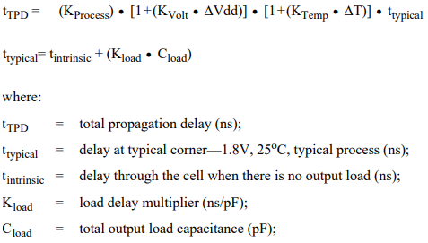
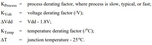
根据提供的比例缩放因子,总传输延时计算公式如下
IO口属性(pad attributes)
output_voltage(GENERAL) {
vol : 0.4;
voh : VDD - 0.4;
vomin : -0.5;
vomax : VDD + 0.5;
}
input_voltage(CMOS) {
vil : 0.3 * VDD;
vih : 0.7 * VDD;
vimin : -0.5;
vimax : VDD + 0.5;
}
......
定义IO管脚的方向、电平属性等
线载模型(wire-loads)
wire_load("smic18_wl10") {
resistance : 8.5e-8; wire单位长度电阻值
capacitance : 1.5e-4; wire单位长度电容值
area : 0.7; wire单位长度面积因子
slope : 66.667; wire斜率
fanout_length (1,66.667); fanout=1时的wire length
}
......
给出wire fanout与wire length的统计关系,用于估算布局前的布线延时。
e.g. 当使用以上smic18_wl10的线载模型,有输出Pin fanout=3时,实际fanout大于模型给出的fanout最大值,延时计算如下
实际fanout(3)减去最大已知fanout(1)
↓
Net length = 66.667 + (3 - 1)* 66.667 = 200.001
↑ ↑
最大已知fanout length slope
Resistance = 8.5e-8 * 200.001 = 1.7 * e-5
Capacitance = 1.5e-4 * 200.001 = 3e-2
Area = 0.7 * 200.001 = 140

 浙公网安备 33010602011771号