Rust Embedded开发环境搭建(Windows)
Rust Embedded开发环境搭建(Windows)
文中的软件和工具在文末获取
硬件
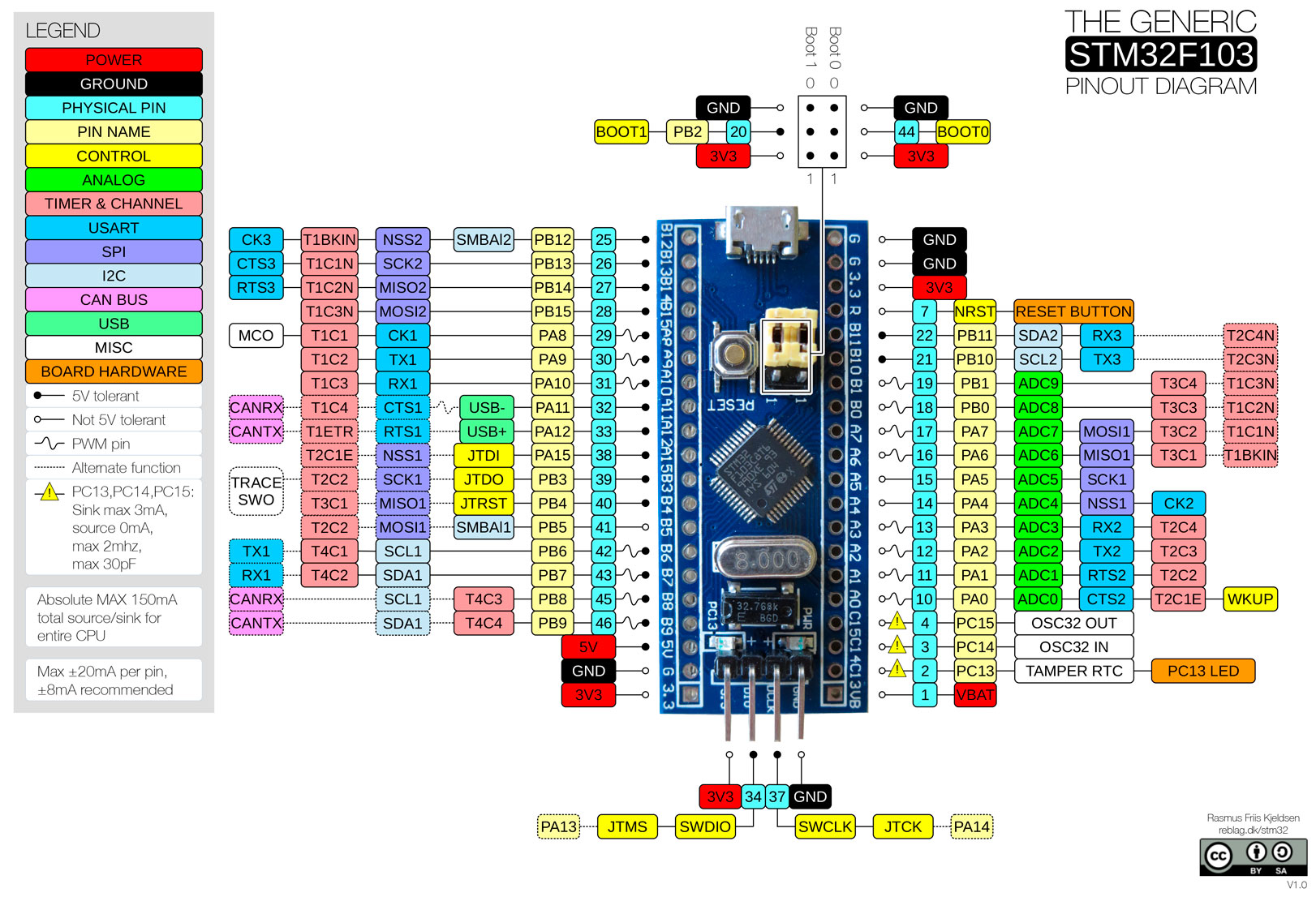
STM32F103 最小系统开发板
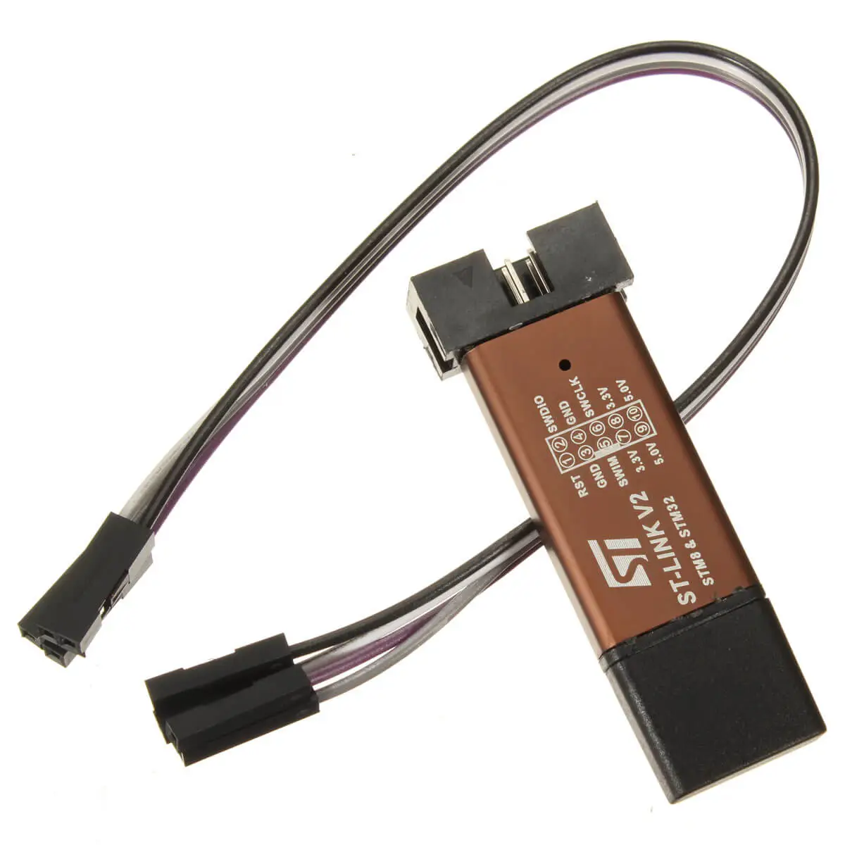
STLINK V2 仿真器
软件
软件下载安装
- Visual Studio Code(编辑器)
- arm-none-eabi-gdb(编译器)
- OpenOCD(调试器)
- ST-LINK USB 驱动程序(驱动程序)
- PuTTY(串口工具)
arm-none-eabi-gdb
打开soft packet安装arm-gnu-toolchain-12.2.rel1-mingw-w64-i686-arm-none-eabi.exe。根据安装向导操作,在安装过程完成之前,勾选/选择 "向环境变量添加路径"选项。然后验证工具是否在 PATH中,若不在则手动添加。
验证是否安装了gcc,按WIN+R输入cmd,在命令行中输入以下:
arm-none-eabi-gcc -v
返回:
(...)
gcc version 12.2.1 20221205 (Arm GNU Toolchain 12.2.Rel1 (Build arm-12.24))
OpenOCD
打开soft packet解压xpack-openocd-0.12.0-1-win32-x64.zip后放在C盘下C:\xpack-openocd-0.12.0-1。向环境变量添加路径C:\xpack-openocd-0.12.0-1\bin。然后验证工具是否在 PATH中,若不在则手动添加。
验证OpenOCD是否已安装并在PATH中,按WIN+R输入cmd,在命令行中输入以下:
openocd -v
返回:
xPack Open On-Chip Debugger 0.12.0-01004-g9ea7f3d64-dirty
(...)
ST-LINK USB 驱动程序
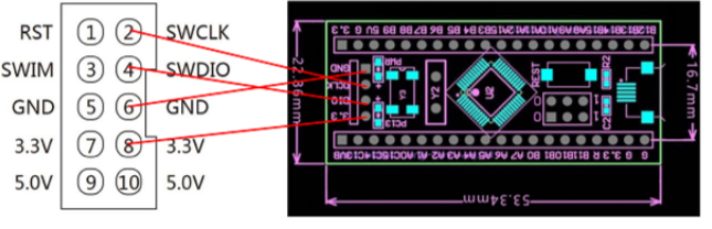
接线:
| ST-LINK V2 | STM32 |
|---|---|
| 3.3V | 3V3 |
| SWDIO | SWIO |
| SWCLK | SWCLK |
| GND | GND |
将ST-LINK USB插入电脑,打开电脑设备管理器,右键未识别的STM32 STLink更新驱动程序:
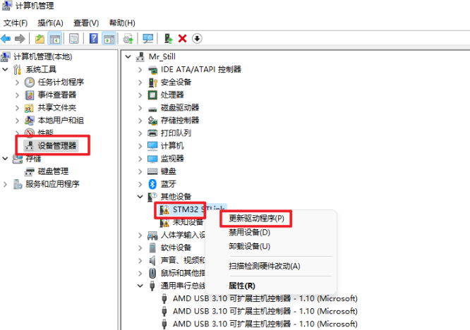
选择以下驱动安装方式:
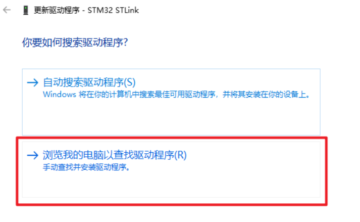
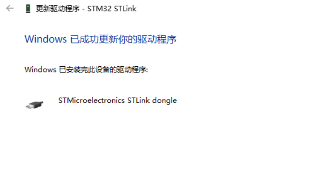
点击“浏览”选择soft packet下STM32仿真器驱动中的ST-LINK驱动,点击"下一步"后显示:
PuTTY
从此网站下载最新的putty.exe并将其放置在PATH中。
开发环境配置
Rust安装
Rust toolchain
-
使用
night-mscvchannel 的Rust编译器工具链。在终端输入:
rustup default nightly-msvc -
安装目标板
core核心库。按照对应架构,选择安装。STM32F103的架构为Cortex-M3,所以这里我们指定的是thumbv7m-none-eabi。Target | Architecture ------------------------------------------------------------ thumbv6m-none-eabi | Cortex-M0 and Cortex-M0+ thumbv7m-none-eabi | Cortex-M3 thumbv7em-none-eabi | Cortex-M4 and Cortex-M7 (no FPU) thumbv7em-none-eabihf | Cortex-M4F and Cortex-M7F (with FPU)
在终端中输入
rustup target add thumbv6m-none-eabi thumbv7m-none-eabi
示例-Blinky
项目全过程
-
创建项目
用VSC打开所建项目文件夹。在终端输入:
cargo new blinky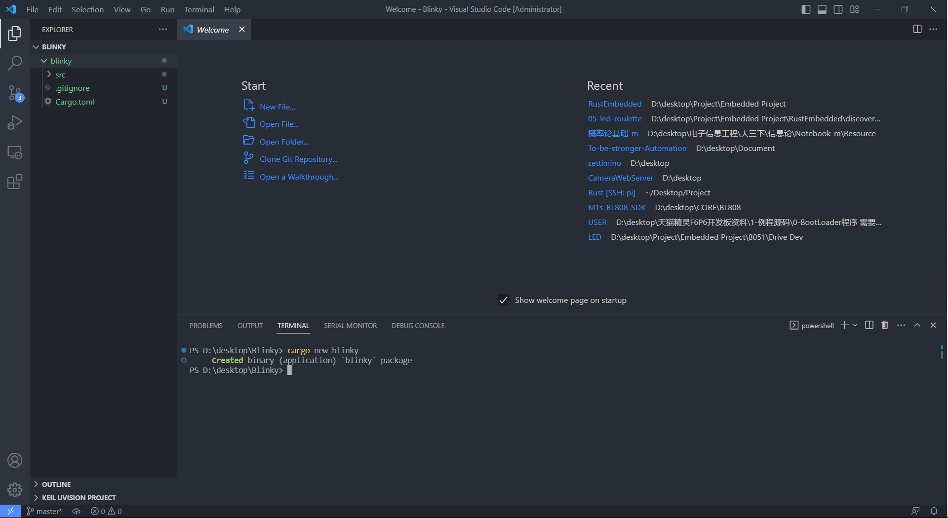
项目创建 -
下载stm32f103xx-hal
在终端输入:
git clone https://github.com/stm32-rs/stm32f1xx-hal.git或将
stm32f1xx-hal复制拷贝在项目文件夹下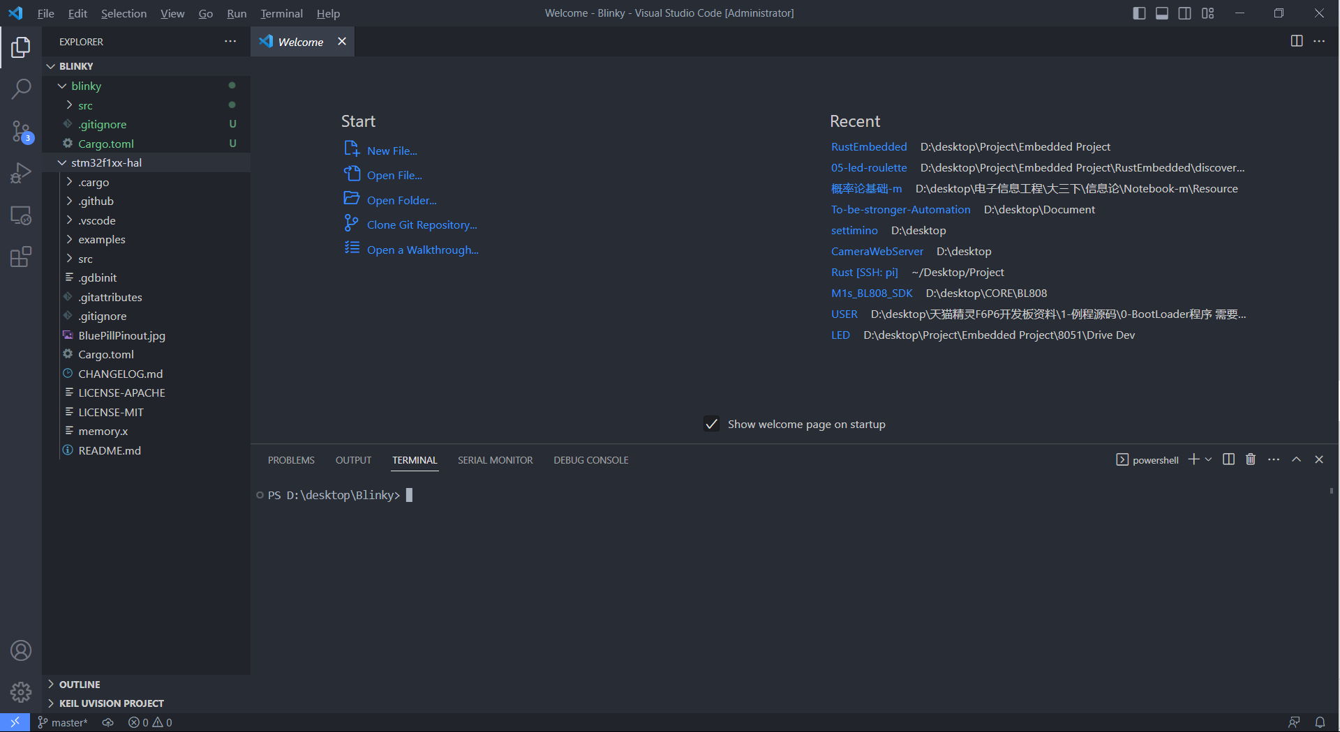
stm32f1xx-hal -
项目配置
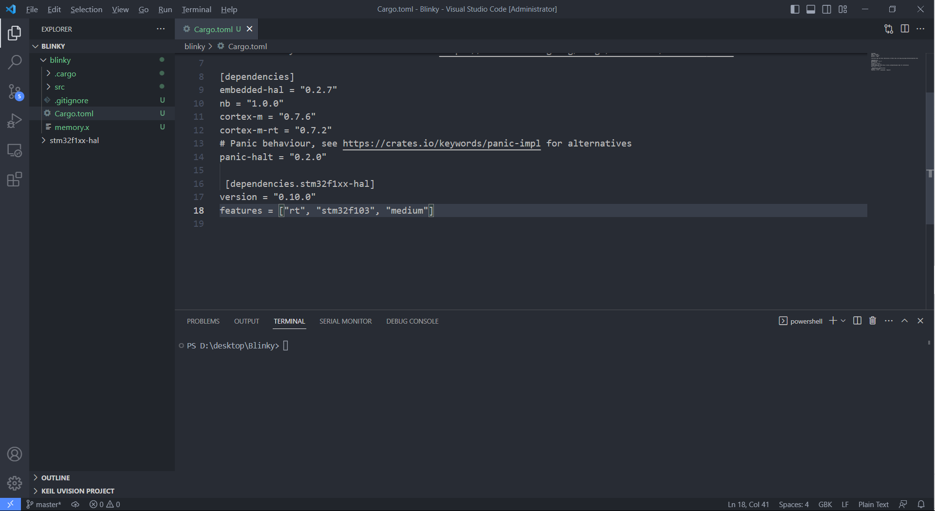
在Cargo.toml添加依赖项:
[dependencies]
 embedded-hal = "0.2.7"
 nb = "1.0.0"
 cortex-m = "0.7.6"
 cortex-m-rt = "0.7.2"
 panic-halt = "0.2.0"

[dependencies.stm32f1xx-hal]
 version = "0.10.0"
 features = ["rt", "stm32f103", "medium"]
再将stm32f1xx-hal 下的.cargo/config 和 memory.x从 stm32f1xx-hal 存储库复制到项目中。
-
程序编写
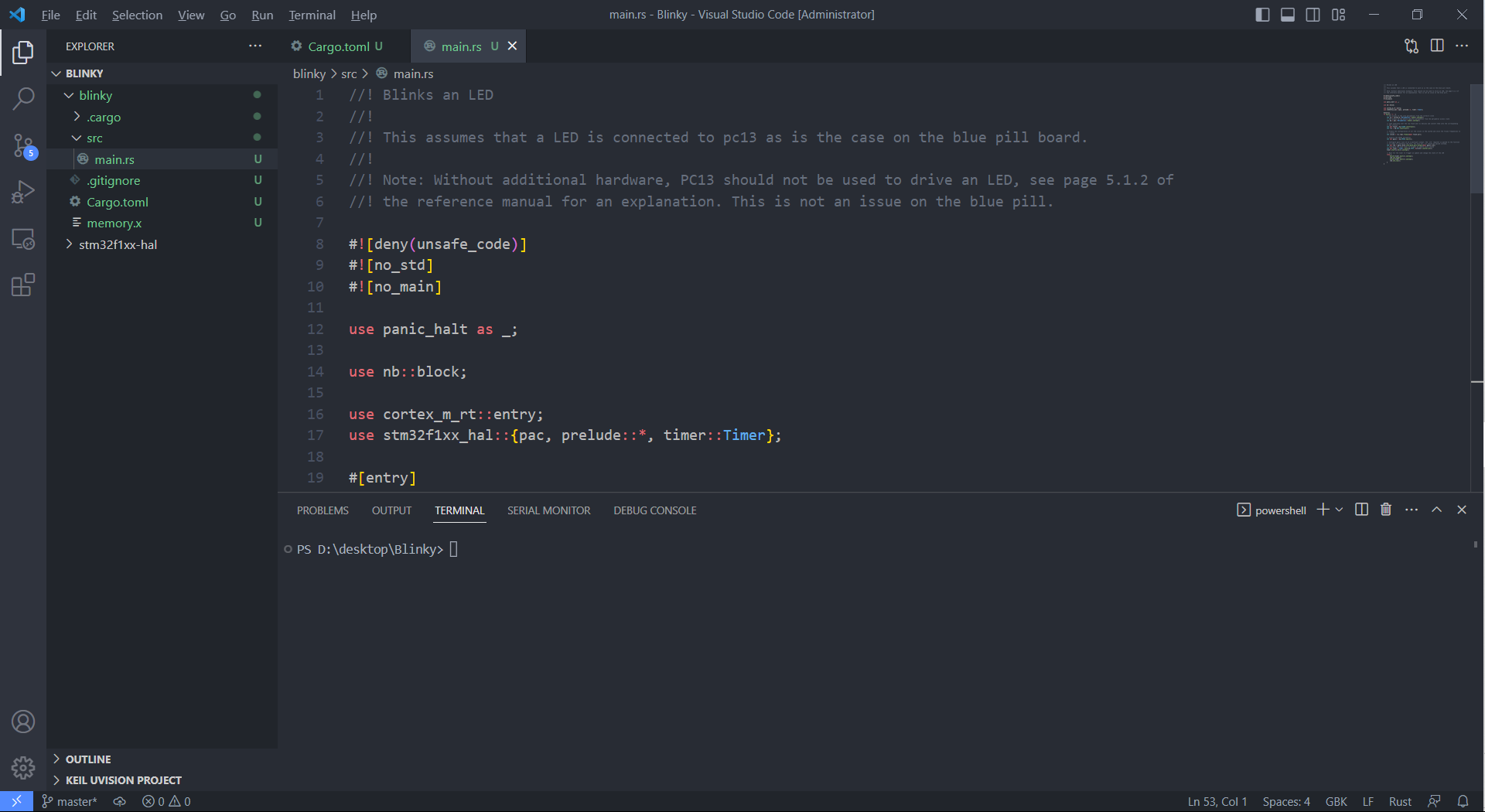
打开
blinky\src\main.rs输入:
 //! Blinks an LED
 //!
 //! This assumes that a LED is connected to pc13 as is the case on the blue pill board.
 //!
 //! Note: Without additional hardware, PC13 should not be used to drive an LED, see page 5.1.2 of
 //! the reference manual for an explanation. This is not an issue on the blue pill.

 #![deny(unsafe_code)]
 #![no_std]
 #![no_main]

 use panic_halt as _;

 use nb::block;

 use cortex_m_rt::entry;
 use stm32f1xx_hal::{pac, prelude::*, timer::Timer};

 #[entry]
 fn main() -> ! {
     // Get access to the core peripherals from the cortex-m crate
     let cp = cortex_m::Peripherals::take().unwrap();
     // Get access to the device specific peripherals from the peripheral access crate
     let dp = pac::Peripherals::take().unwrap();

     // Take ownership over the raw flash and rcc devices and convert them into the corresponding
     // HAL structs
     let mut flash = dp.FLASH.constrain();
     let rcc = dp.RCC.constrain();

     // Freeze the configuration of all the clocks in the system and store the frozen frequencies in
     // `clocks`
     let clocks = rcc.cfgr.freeze(&mut flash.acr);

     // Acquire the GPIOC peripheral
     let mut gpioc = dp.GPIOC.split();

     // Configure gpio C pin 13 as a push-pull output. The `crh` register is passed to the function
     // in order to configure the port. For pins 0-7, crl should be passed instead.
     let mut led = gpioc.pc13.into_push_pull_output(&mut gpioc.crh);
     // Configure the syst timer to trigger an update every second
     let mut timer = Timer::syst(cp.SYST, &clocks).counter_hz();
     timer.start(1.Hz()).unwrap();

     // Wait for the timer to trigger an update and change the state of the LED
     loop {
         block!(timer.wait()).unwrap();
         led.set_high();
         block!(timer.wait()).unwrap();
         led.set_low();
     }
 }
-
编译
终端输入:
cd blinky
cargo build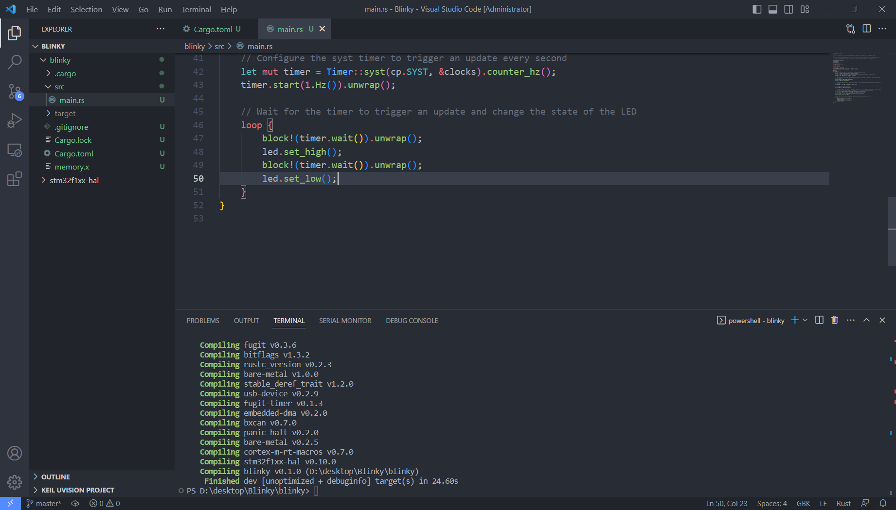
编译成功 -
调试
a) STLink USB插入电脑,在VSC中新建终端输入:
openocd -f interface/stlink-v2.cfg -f target/stm32f1x.cfg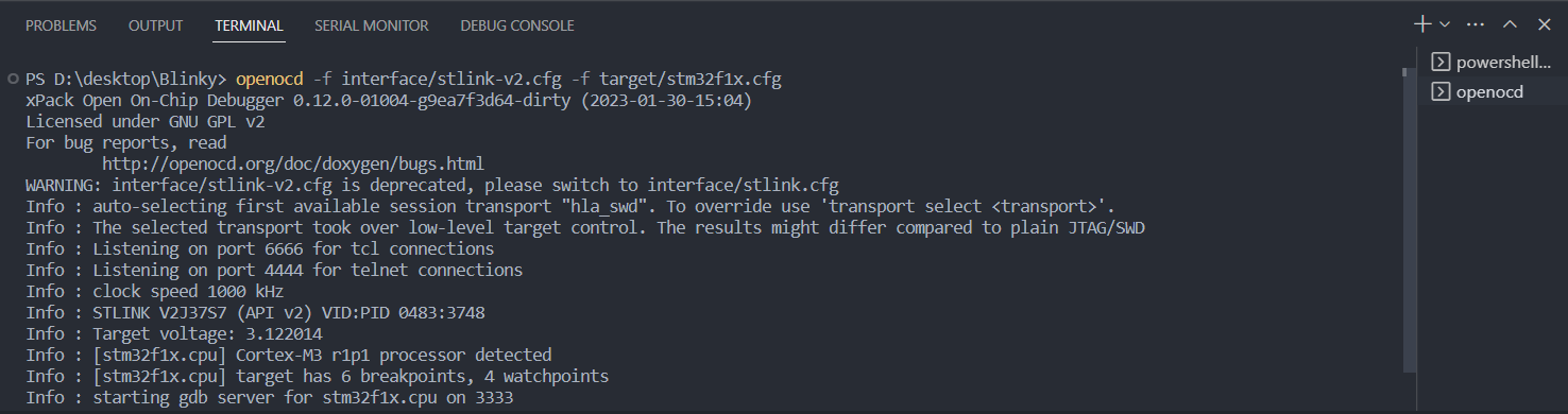
b)再次新建终端输入:
arm-none-eabi-gdb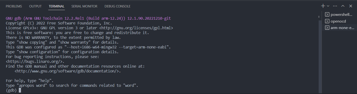
c) 加载目标文件。在
arm-none-eabi-gdb终端输入:file blinky/target/thumbv7m-none-eabi/debug/blinky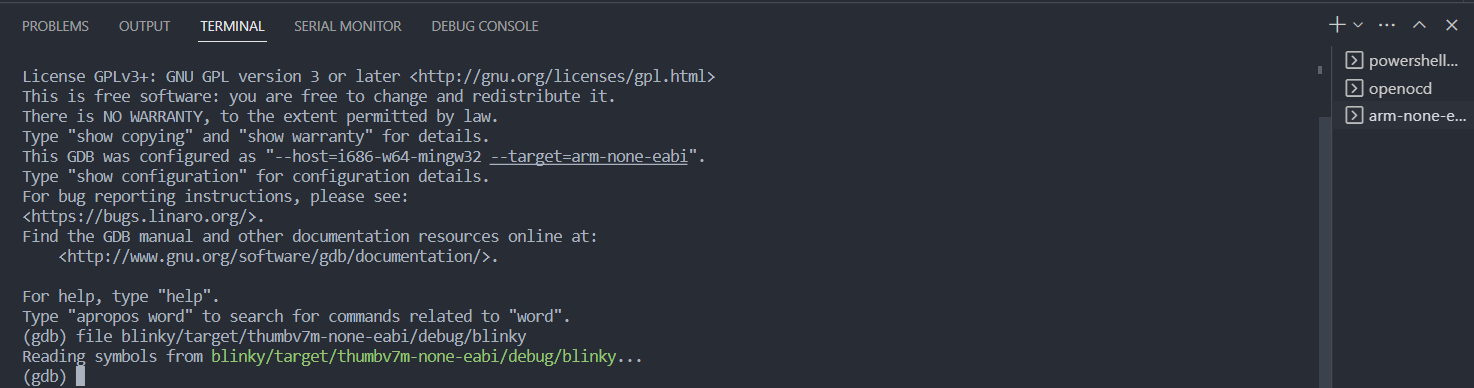
d) 连接上
openocd。在arm-none-eabi-gdb终端输入:target remote :3333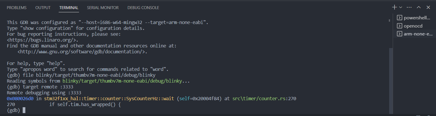
e) 重置MCU。在
arm-none-eabi-gdb终端输入:monitor reset halt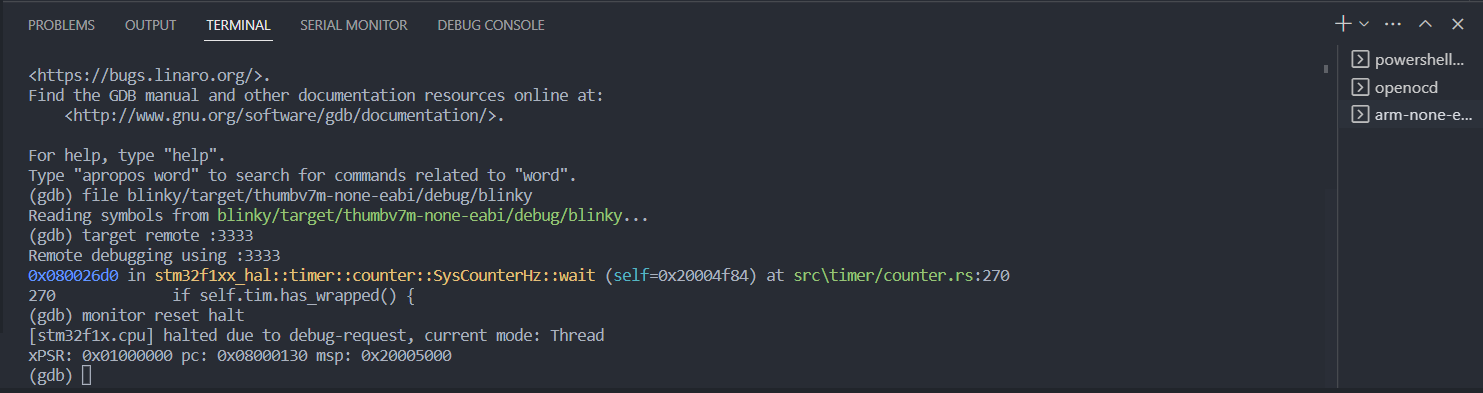
f) 写入(烧录)。在
arm-none-eabi-gdb终端输入:load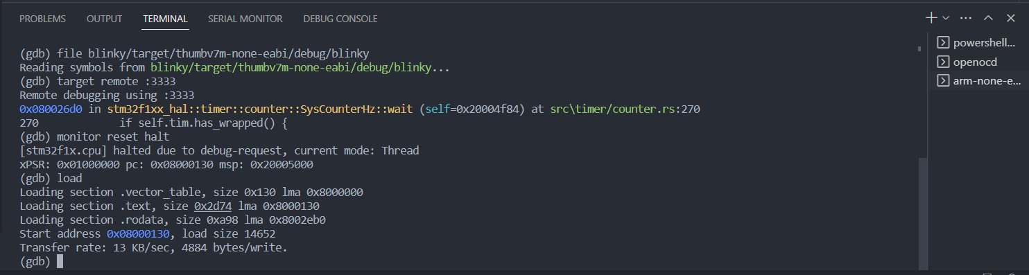
g) 运行。在
arm-none-eabi-gdb终端输入:continue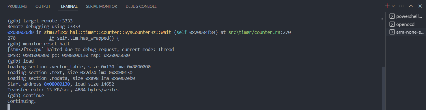
现象

板载蓝色LED灯每隔一秒亮灭。
链接:https://pan.baidu.com/s/1e7-IFRC2yaRiBarKWk5cfA?pwd=6ncd
提取码:6ncd

 浙公网安备 33010602011771号