PID控制器(比例-积分-微分控制器)- V
Linear Actuator - PID Control
Introduction
This application guide is designed to explain the basics of PID control and how to implement a basic control loop using Phidgets.
Once implemented, the control loop will allow the linear actuator to move to a precise position and remain there, even if an external force tries to move it.
PID Control Basics
Proportional Control
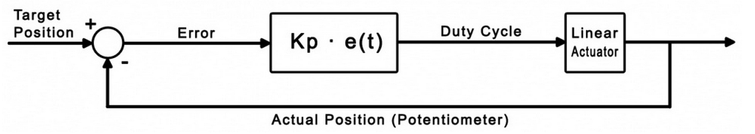
The goal of a control loop is to use data from the feedback device (in this case, the potentiometer) to iteratively adjust the output
until it has reached the target value.
For example, consider this simple control loop (This code would be used in the sensor change event handler):
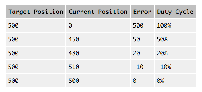
DutyCycle = TargetPosition - ActualPosition;
if (DutyCycle > 100)
     DutyCycle = 100;
if (DutyCycle < -100)
     DutyCycle = -100;
Whenever the potentiometer value (ActualPosition) changes, the event handler triggers and updates the Duty Cycle of the motor.
Eventually, this will result in the motor reaching its target. The following table further illustrates how this works:
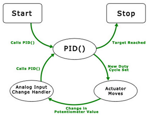
This diagram illustrates the flow of the simple control loop being implemented.
The function PID() is called, which sets a new duty cycle, which causes the actuator to move.
Eight milliseconds later, the potentiometer that keeps track of how far the actuator has extended causes an analog input change event,
which in turn calls PID() again. The cycle continues until the target position is reached.
The type of control we've just implemented here is called Proportional control,
because the output is directly proportional to the error.
We can multiply (TargetPosition - ActualPosition) by a gain value if we want to control how the control loop behaves when it gets close to the target.
A lower value (i.e. less than 1) will result in a more gradual reduction in speed as the actuator reaches its target position,
while a larger value will result in a sharper, quicker response.
We'll call this value the proportional gain, or Kp for short.
If the proportional gain is set too high, the actuator will overshoot the target position and oscillate back and forth around the target.
While we've gained basic control of the actuator position, there are still some problems with purely proportional control.
You may find that the actuator never quite reaches the target position, especially with a low proportional gain.
Also, if the load on the actuator changes while it's moving, it won't be able to react to the difference.
To solve these problems, we need an integral term.
Integral Control
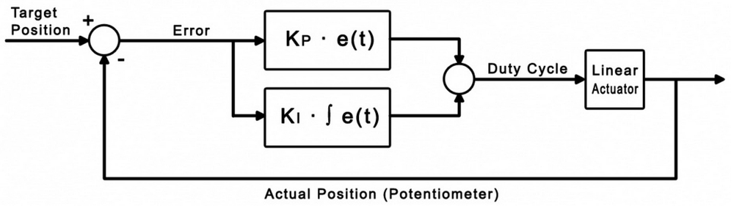
The purpose of the integral term in a control loop is to look back at all of the past error
and accumulate it into an offset that the control loop can use.
Combined with our proportional control loop, it will be able to react to changes in load and land closer
to the target position if we choose our gain values properly.
dt = 0.008;
error = TargetPosition - ActualPosition;
DutyCycle = (Kp * error) + (Ki * integral);

if (DutyCycle > 100)
     DutyCycle = 100;
else if (DutyCycle < -100)
     DutyCycle = -100;
else
     integral += (error * dt);
Where dt is the change in time between iterations of the control loop.
For this example, dt is set to 0.008 seconds, which is the update rate of the analog input.
The integral is only accumulated when the duty cycle isn't saturated at 100% or -100%.
This prevents the control loop from needlessly accumulating the integral when it's already running at maximum velocity.
Now we have two control gains: Kp and Ki.
Kp still functions as it did in the proportional example, and Ki controls how influential the integral term is.
Increasing the integral gain will cause the control loop to reach the target faster,
and ensure that you hit the exact target rather than settling to a value close to the target.
Just like the proportional gain, increasing the integral gain too much can cause instability.
After tweaking the control gains, you may find that PI control is sufficient for your application.
If you're having trouble finding control gains that provide the results you're looking for, y
ou can implement full PID control by adding the derivative term.
Derivative Control
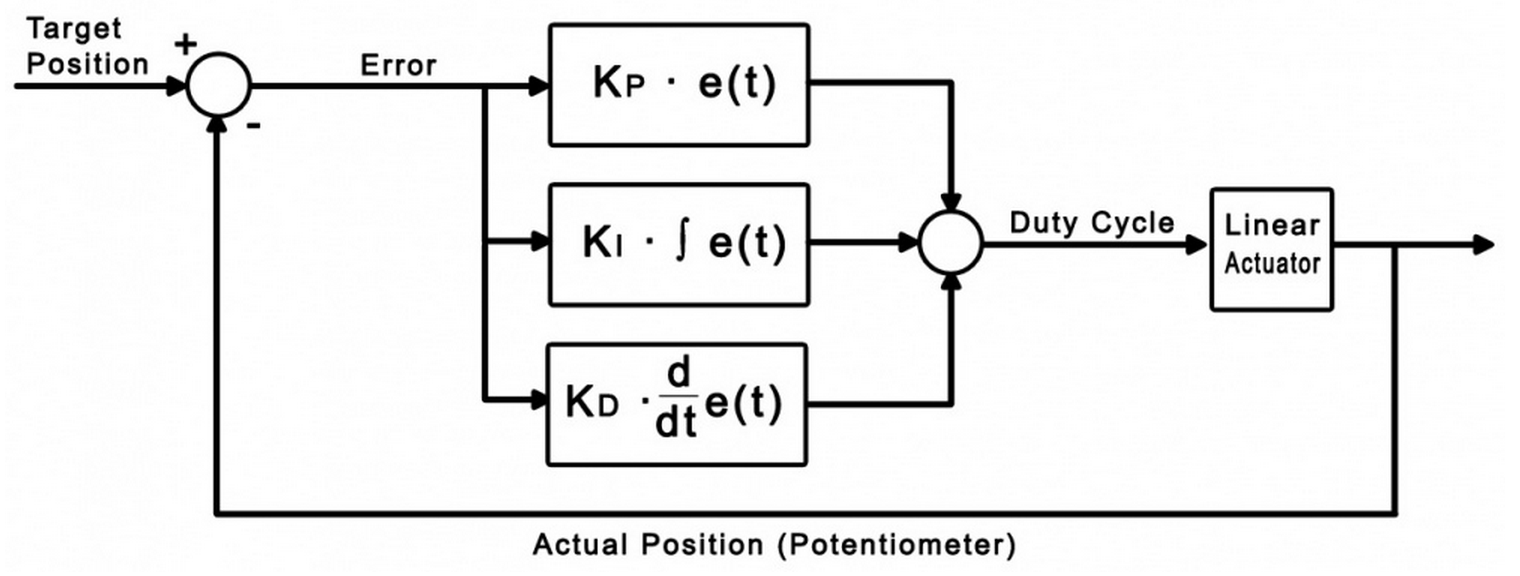
Derivative control looks at past errors in the system and calculates the slope of those errors to predict future error values.
Adding derivative control should add stability to the system and increase the control we have over it by adding another gain value.
dt = 0.008;
error = TargetPosition - ActualPosition;
DutyCycle = (Kp * error) + (Ki * integral) + (Kd * derivative);

if (DutyCycle > 100)
     DutyCycle = 100;
else if (DutyCycle < -100)
     DutyCycle = -100;
else
     integral += (error * dt);

derivative = (error - errorlast)/dt;
Where errorlast is the error value a set number of samples ago.
In an application such as this, an error value from around 64 samples ago (0.5 seconds) should suffice.
Just as before, we can now use Kd to modify the weight of this new derivative term.
Increasing Kd should smooth things out and increase stability,
but you'll find that it should be kept small in comparison to the other control gains
or it will cause the control to oscillate when it's near the target.
Sample Program
You can download the sample program written for this guide via the link below. This is a Visual C# project.
Controls and Settings
- These boxes contain the information of the attached motor controller. If these boxes are blank, it means the controller object didn't successfully attach.
- These boxes control which motor output and analog input are being used, and allow you to set each of the control gains. You can click on the "?" icon in the top right for more information on a particular setting. Changes will not take effect until the "Start" button is hit.
- These boxes display the target position set by the slider and the actual position according to the feedback potentiometer. The error is the difference between these two values, and the output velocity is the duty cycle of the controller as dictated by the control loop.
- The maximum velocity slider controls the maximum duty cycle that the controller will output. It is unrestricted (100%) by default.
- This slider selects the target position, from 1 to 1000 sensorvalue of the feedback potentiometer.
- Pressing the start button will initiate the control loop and the actuator will begin to move toward the target position. If the actuator does not move, check your power and connections.
- These settings are for actuators whose potentiometers don't span the full range of 0-5V (0 - 1000 sensorvalue). Experiment with your actuator to discover the potentiometer's limits.
- This graph will plot the motor's position and the target position over time.
Algorithm
The PID control algorithm in this sample program operates by setting up a change handler for the analog input connected
to the feedback potentiometer that calls an external function.
This function computes the PID control loop output as briefly described in the previous section.
By changing the output, the motor's duty cycle is set and the function will be called again the next time the sensor change handler triggers
(in 0.008 seconds, because the sampling period of an analog input is 8ms).
This loop will continue until the output of the control loop is zero, at which point the sensor change event will no longer trigger.
// This is the event handler for the attached feedback sensor
void actuator_SensorUpdate(object sender, SensorUpdateEventArgs e)
{
    // If the selected sensor input is the one that triggered this handler,
    if ((e.Index == 0 && analogCmb.Text == "0") || (e.Index == 1 && analogCmb.Text == "1"))
    {
        //Store sensor value in global variable
        feedback = e.Value;

        //Run the PID loop
        if (started)
        {
            PID();
        }

        //Update the motor controller with the new duty cycle
        actuator.motors[Convert.ToInt32(motorCmb.Text)].Velocity = Math.Round(output);
    }
}
It's always a good idea to keep your event handlers as small and optimized as possible to avoid missing events.
In this sample program, all of the complexity of the PID algorithm is tucked away in the function "PID( )".
The PID() function:
- Updates error variables
- Checks to see if the actuator has reached its target (and if it has, stops the loop)
- Updates the the output (duty cycle) of the control loop
- Limits the duty cycle to the specified output limit
- Updates the derivative variable
In the downloadable example, this function also updates the graph and all of the text boxes that track the variables.
These lines were removed from the excerpt below for increased readability.
// This function does the control system calculations and sets output to the duty cycle that the motor needs to run at.
void PID()
{
    // Calculate how far we are from the target
    errorlast = error;
    error = input - feedback;

    // If the error is within the specified deadband, and the motor is moving slowly enough,
    // Or if the motor's target is a physical limit and that limit is hit (within deadband margins),
    if ((Math.Abs(error) <= deadBand && Math.Abs(output) < 5)
        || (input < (deadBand + 1 + (double)svMinTxt.Value) && feedback < (deadBand + 1 + (double)svMinTxt.Value))
        || (input > ((double)svMaxTxt.Value - (1 + deadBand)) && feedback > ((double)svMaxTxt.Value - (1 + deadBand))))
    {
        // Stop the motor
        output = 0;
        error = 0;
    }
    else
    {
        // Else, update motor duty cycle with the newest output value
        // This equation is a simple PID control loop
        output = ((Kp * error) + (Ki * integral)) + (Kd * derivative);
        errorTxt.Text = error.ToString();
    }


    //Prevent output value from exceeding maximum output specified by user, otherwise accumulate the integral
    if (output >= maxOutput)
        output = maxOutput;
    else if (output <= -maxOutput)
        output = -maxOutput;
    else
        integral += (error * dt);

    derivative = (error - errorlast) / dt;
}

 浙公网安备 33010602011771号