Adding Digital control to Dual tracking LM317 / LM337 Bench supply
Adding Digital control to Dual tracking LM317 / LM337 Bench supply
I've been working on my own idea for a digitally controlled power supply over the last couple of weeks,
originally using a MIC29302 which didn't look too bad, and a handful of DACs and ADCs to go with it,
however I abandoned that project when I realised that it would cost me over $200 just to get the parts/boards.
So I headed back into the LM317 route again.
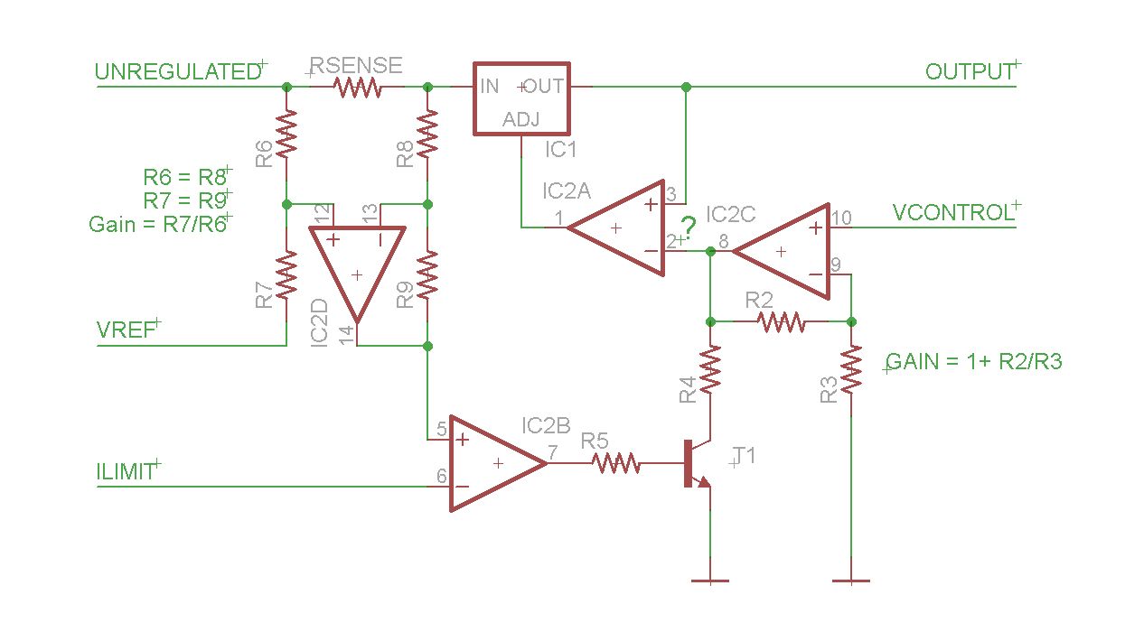
Following some of Dave's designs I came up with the attached Schematic so far.
Most of the important info is there, apart from the Opamp needing to be powered from a voltage rail
that goes up to 1.25V under the Maximum output voltage you want,
and down to a minimum -1.25 so that you can get true 0v output.
The question mark next to the input pins on gate A is there because i'm not 100% certain on the orientation,
so I'll have to try that out on a breadboard.
I think I might need to swap them to have it work right. (and the more I look at it the more certain I become)
I'm also not 100% what voltage Vref should be at, but again, that will require testing on a breadboard.
The current limiting and voltage control have a number of ways that they could work.
A pot, DAC, uController PWM with a filter, would all be options.
If anyone wants to make a comment on the design, please feel free to.
-kizzap
Edit: Doing some more thinking, I'm not entirely sure about where I have the current limiting connected at the moment either,
I might have to place a resistor between the output of gate A and the LM317 adjust pin,
and move R4 over to there as well to create a voltage divider there.
It won't work. Problem trying to pull down the output of an op amp. It is definitely an electron faux pas.
Were you referring to me? if so in what part?
Just went and started testing the circuit on a breadboard,
so far I have tested just the op-amp driving the adjust pin and it is working good.
Then I proceeded to blow the 317 up in some form of glory for the silicon Gods.
May have had something to do with me drawing a bit of current out (whoops),
or the fact that I had the pot connected between the + and - rails, and not + to GND.
Back to the drawing boards to get this thing right.
Sorry for Hi-jacking N TYPE
-kizzap

 浙公网安备 33010602011771号