PE Header and Export Table for Delphi
Malware Analysis Tutorial 8: PE Header and Export Table
2. Background Information of PE Header
Any binary executable file (no matter on Unix or Windows) has to include a header to describe its structure:
e.g., the base address of its code section, data section, and the list of functions that can be exported from the executable, etc.
When the file is executed by the operating system, the OS simply reads this header information first,
and then loads the binary data from the file to populate the contents of
the code/data segments of the address space for the corresponding process.
When the file is dynamically linked (i.e., the system calls it relies on are not statically linked in the executable),
the OS has to rely on its import table to determine where to find the entry addresses of these system functions.
Most binary executable files on Windows follows the following structure:
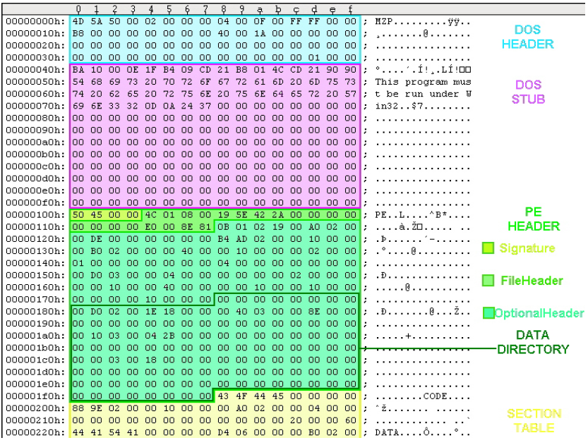
DOS Header (64 bytes),
PE Header,
sections (code and data).
For a complete survey and introduction of the executable file format,
we recommend Goppit's "Portable Executable File Format - A Reverse Engineering View" [1].
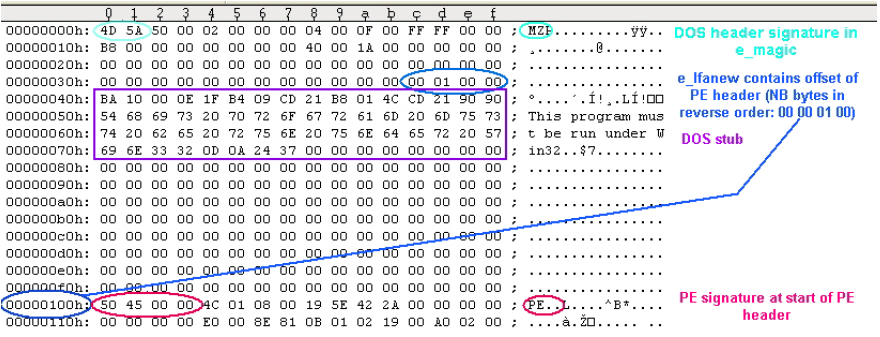
DOS Header starts with magic number 4D 5A 50 00,
and the last 4 bytes is the location of PE header in the binary executable file.
Other fields are not that interesting.
The PE header contains significantly more information and more interesting.
In Figure 1, please find the structure of PE Header.
We only list the information that are interesting to us in this tutorial.
For a complete walk-through, please refer to Goppit's work [1].

Figure 1. Structure of PE Header
As shown in Figure 1, PE header consists of three parts:
(1) a 4-byte magic code,
(2) a 20-byte file header and its data type is IMAGE_FILE_HEADER, and
(3) a 224-byte optional header (type: IMAGE_OPTIONAL_HEADER32).
The optional header itself has two parts:
the first 96 bytes contain information such as major operating systems, entry point, etc.
The second part is a data directory of 128 bytes.
It consists of 16 entries, and each entry has 8 bytes (address, size).
4 + 20 + [ 224 = ( 96 + 8 * 16 ) ]
We are interested in the first two entries: one has the pointer to the beginning of the export table, and the other points to the import table.
2.1 Debugging Tool Support (Small Lab Experiments)
Modern binary debuggers have provided sufficient support for examining PE headers.
We discuss the use of WinDbg and Immunity Debugger.
(1) WinDbg.
Assume that we know that the PE structure of ntdll.dll is located at memory address 0x7C9000E0.
We can display the second part: file header using the following.
Then we can calculate the starting address of the optional header:
0x7C9000E4 + 0x14 (20 bytes) = 0x7C9000F8. < IMAGE_FILE_HEADER 20 bytes >
The attributes of optional header is displayed as below.
For example, the major linker version is 7 and the the address of entry point is 0x12c28
(relative of the base address 0x7c900000).
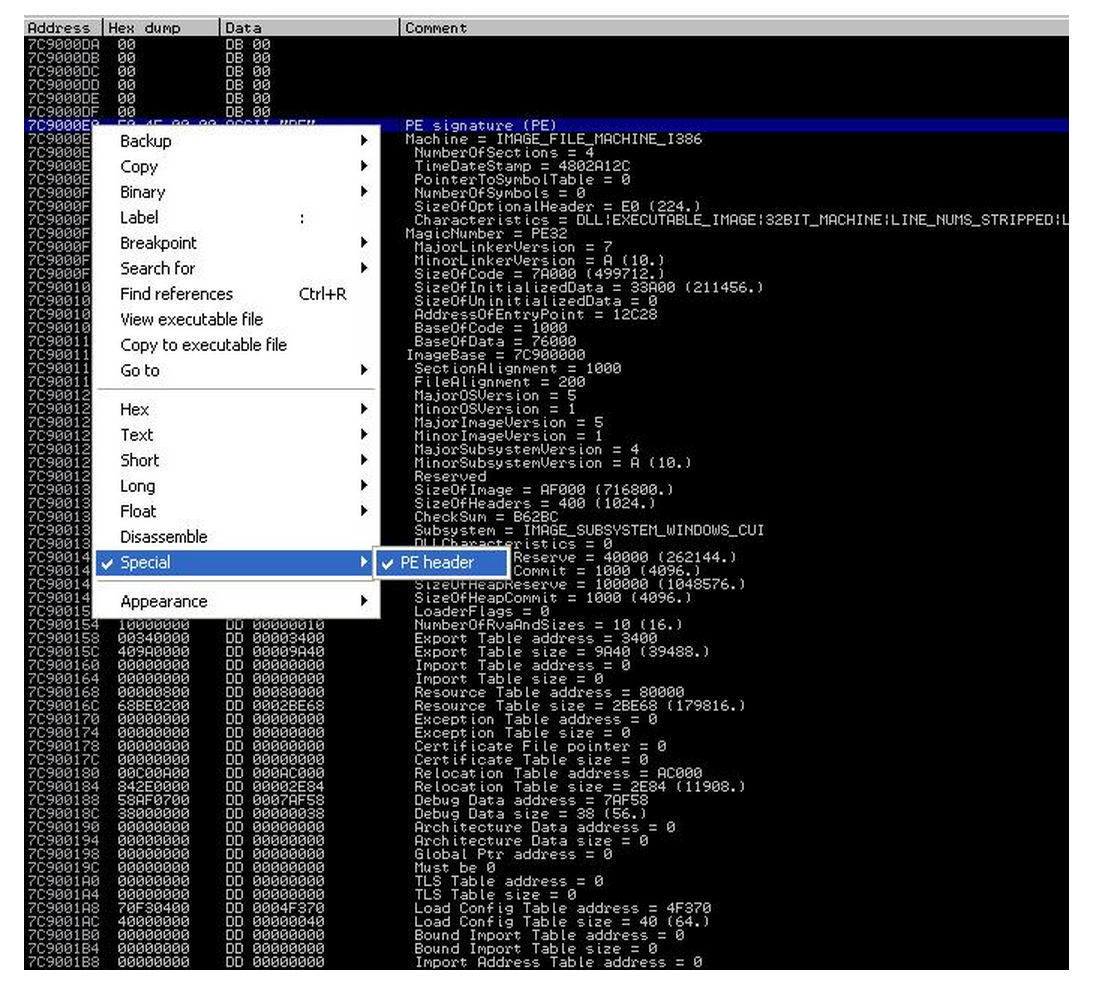
As shown by Goppit [1], OllyDbg can display PE structure nicely.
Since the Immunity Debugger is based on OllyDbg, we can achieve the same effect.
In IMM View -> Memory, we can easily locate the starting address of each module (e.g., see Figure 2).

Then in the memory dump window, jump to the starting address of the PE of ntdll.dll.
Then right click in the dump pane, and select special -> PE, we can have all information nicely presented by IMM.
3. Export Table
Recall that the first entry of IMAGE_DATA_DIRECTORY of the optional header field contains information about the export table. By Figure 1, you can soon infer that the 4 bytes located at PE + 0x78 (i.e., offset 120 bytes) is the relative address (relative to DLL base address) of the export table, and the next byte (at offset 0x7C) is the size of the export table.
The data type for the export table is IMAGE_EXPORT_DIRECTORY. Unfortunately, the WinDbg symbol set does not include the definition of this data structure, but you can easily find it in winnt.h through a google search (e.g., from [2]). The following is the definition of IMAGE_EXPORT_DIRECTORY from [2].
typedef struct _IMAGE_EXPORT_DIRECTORY {
DWORD Characteristics; //offset 0x0
DWORD TimeDateStamp; //offset 0x4
WORD MajorVersion; //offset 0x8
WORD MinorVersion; //offset 0xa
DWORD Name; //offset 0xc
DWORD Base; //offset 0x10
DWORD NumberOfFunctions; //offset 0x14
DWORD NumberOfNames; //offset 0x18
DWORD AddressOfFunctions; //offset 0x1c
DWORD AddressOfNames; //offset 0x20
DWORD AddressOfNameOrdinals; //offset 0x24
}
Here, we need some manual calculation of addresses for each attribute for our later analysis. In the above definition, WORD is a computer word of 16 bites (2bytes), and DWORD is 4 bytes. We can easily infer that, MajorVersion is located at offset 0x8, and AddressOfFunctions is located at offset 0x1c.
Now assume that IMAGE_EXPORT_DIRECTORY is located at 0x7C903400, the following is the dump from WinDbg (here "dd" is to display memory):
kd> dd 7c903400
7c903400 00000000 48025c72 00000000 00006786
7c903410 00000001 00000523 00000523 00003428
7c903420 000048b4 00005d40 00057efb 00057e63
7c903430 00057dc5 00002ad0 00002b30 00002b40
7c903440 00002b20 0001eb58 0001ebb9 0001e3af
7c903450 0002062d 000206ee 0004fe3a 00012d71
7c903460 000211e7 0001eaff 0004fe2f 0004fdaa
7c903470 0001b08a 0004febb 0004fe6d 0004fde6
We can soon infer that there are 0x523 functions exposed in the export table, and there are 0x523 names exposed. Why? Because the NumberOfFunctions is located at offset 0x14 (thus its address is 0x7c903400+0x14 = 0x7c903414) For another example, look at the attribute "Name" which is located at offset 0xc (i.e., its address: 0x7c90340c), we have number 0x00006787. This is the address relative to the base DLL address (assume it is 0x7c900000). Then we have the name of the module located at 0x7c906786. We can verify using the "db" command in WinDbg (display memory contents as bytes): you can verify that the module name is indeed ntdll.dll.
kd> db 7c906786
7c906786 6e 74 64 6c 6c 2e 64 6c-6c 00 43 73 72 41 6c 6c ntdll.dll.CsrAll
7c906796 6f 63 61 74 65 43 61 70-74 75 72 65 42 75 66 66 ocateCaptureBuff
Read page 26 of [1], you will find that the "AddressOfFunctions", "AddressOfNames", and "AddressOfNameOdinals" are the most important attributes. There are three arrays (shown as below), and each of the above attributes contains one corresponding starting address of an array.
For example, by manual calculation we know that the Names array starts at 7C9048B4 (given the 0x48B4 located at offset 0x20, for attribute AddressOfNames; and assuming the base address is 0x7C900000). We know that each element of the Names array is 4 bytes. here is the dump of the first 8 elements:
kd> dd 7c9048b4
7c9048b4 00006790 000067a9 000067c3 000067db
7c9048c4 00006807 0000681f 00006831 00006845
We can verify the first name (00006790): It's CsrAllocateCaptureBuffer. Note that a "0" byte is used to terminate a string.
kd> db 7c906790
7c906790 43 73 72 41 6c 6c 6f 63-61 74 65 43 61 70 74 75 CsrAllocateCaptu
7c9067a0 72 65 42 75 66 66 65 72-00 43 73 72 41 6c 6c 6f reBuffer.CsrAllo
We can also verify the second name (000067a9): It's CsrAllocateMessagePointer.
kd> db 7c9067a9
7c9067a9 43 73 72 41 6c 6c 6f 63-61 74 65 4d 65 73 73 61 CsrAllocateMessa
7c9067b9 67 65 50 6f 69 6e 74 65-72 00 43 73 72 43 61 70 gePointer.CsrCap
Now, given a Function name, how do we find its entry address? The following is the formula:
Note that array index starts from 0.
Assume Names[x].equals(FunctionName)
Function address is Functions[Ordinal[x]]
4. Challenge1 of the Day
The first sixteen elements of the Ordinal is shown below:
kd> dd 7c905d40
7c905d40 00080007 000a0009 000c000b 000e000d
7c905d50 0010000f 00120011 00140013 00160015
The first eight elements of the Functions array is shown below:
kd> dd 7c903428
7c903428 00057efb 00057e63 00057dc5 00002ad0
7c903438 00002b30 00002b40 00002b20 0001eb58
What is the entry address of function CsrAllocateCaptureBuffer? The answer is: it's 7C91EB58.
Think about why? (Pay special attention to the byte order of integers).
Windows PE Header
Microsoft migrated to the PE format with the introduction of the Windows NT 3.1 operating system.
All later versions of Windows, including Windows 95/98/ME, support the file structure.
The format has retained limited legacy support to bridge the gap between DOS-based and NT systems.
For example, PE/COFF headers still include an MS-DOS executable program,
which is by default a stub that displays the simple message "This program cannot be run in DOS mode" (or similar).

PE also continues to serve the changing Windows platform.
Some extensions include the .NET PE format (see below), a 64-bit version called PE32+ (sometimes PE+),
and a specification for Windows CE.


The Portable Executable File Format from Top to Bottom
Randy Kath
Microsoft Developer Network Technology Group
Download the EXEVIEW sample. (Afterwards, use PKUNZIP.EXE -d to recreate directory structure.)
Download the PEFILE sample. (Afterwards, use PKUNZIP.EXE -d to recreate directory structure.)
Abstract
The Windows NT version 3.1 operating system introduces a new executable file format called the Portable Executable (PE) file format. The Portable Executable File Format specification, though rather vague, has been made available to the public and is included on the Microsoft Developer Network CD (Specs and Strategy, Specifications, Windows NT File Format Specifications).
Yet this specification alone does not provide enough information to make it easy, or even reasonable, for developers to understand the PE file format. This article is meant to address that problem. In it you'll find a thorough explanation of the entire PE file format, along with descriptions of all the necessary structures and source code examples that demonstrate how to use this information.
All of the source code examples that appear in this article are taken from a dynamic-link library (DLL) called PEFILE.DLL. I wrote this DLL simply for the purpose of getting at the important information contained within a PE file. The DLL and its source code are also included on this CD as part of the PEFile sample application; feel free to use the DLL in your own applications. Also, feel free to take the source code and build on it for any specific purpose you may have. At the end of this article, you'll find a brief list of the functions exported from the PEFILE.DLL and an explanation of how to use them. I think you'll find these functions make understanding the PE file format easier to cope with.
Introduction
The recent addition of the Microsoft® Windows NT operating system to the family of Windows operating systems brought many changes to the development environment and more than a few changes to applications themselves. One of the more significant changes is the introduction of the Portable Executable (PE) file format. The new PE file format draws primarily from the COFF (Common Object File Format) specification that is common to UNIX® operating systems. Yet, to remain compatible with previous versions of the MS-DOS® and Windows operating systems, the PE file format also retains the old familiar MZ header from MS-DOS.
In this article, the PE file format is explained using a top-down approach. This article discusses each of the components of the file as they occur when you traverse the file's contents, starting at the top and working your way down through the file.
Much of the definition of individual file components comes from the file WINNT.H, a file included in the Microsoft Win32 Software Development Kit (SDK) for Windows NT. In it you will find structure type definitions for each of the file headers and data directories used to represent various components in the file. In other places in the file, WINNT.H lacks sufficient definition of the file structure. In these places, I chose to define my own structures that can be used to access the data from the file. You will find these structures defined in PEFILE.H, a file used to create the PEFILE.DLL. The entire suite of PEFILE.H development files is included in the PEFile sample application.
In addition to the PEFILE.DLL sample code, a separate Win32-based sample application called EXEVIEW.EXE accompanies this article. This sample was created for two purposes: First, I needed a way to be able to test the PEFILE.DLL functions, which in some cases required multiple file views simultaneously--hence the multiple view support. Second, much of the work of figuring out PE file format involved being able to see the data interactively. For example, to understand how the import address name table is structured, I had to view the .idata section header, the import image data directory, the optional header, and the actual .idata section body, all simultaneously. EXEVIEW.EXE is the perfect sample for viewing that information.
Without further ado, let's begin.
Structure of PE Files
The PE file format is organized as a linear stream of data. It begins with an MS-DOS header, a real-mode program stub, and a PE file signature. Immediately following is a PE file header and optional header. Beyond that, all the section headers appear, followed by all of the section bodies. Closing out the file are a few other regions of miscellaneous information, including relocation information, symbol table information, line number information, and string table data. All of this is more easily absorbed by looking at it graphically, as shown in Figure 1.
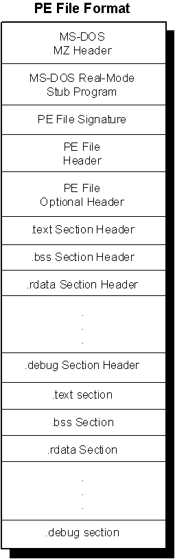
Figure 1. Structure of a Portable Executable file image
Starting with the MS-DOS file header structure, each of the components in the PE file format is discussed below in the order in which it occurs in the file. Much of this discussion is based on sample code that demonstrates how to get to the information in the file. All of the sample code is taken from the file PEFILE.C, the source module for PEFILE.DLL. Each of these examples takes advantage of one of the coolest features of Windows NT, memory-mapped files. Memory-mapped files permit the use of simple pointer dereferencing to access the data contained within the file. Each of the examples uses memory-mapped files for accessing data in PE files.
Note Refer to the section at the end of this article for a discussion on how to use PEFILE.DLL.
MS-DOS/Real-Mode Header
As mentioned above, the first component in the PE file format is the MS-DOS header. The MS-DOS header is not new for the PE file format. It is the same MS-DOS header that has been around since version 2 of the MS-DOS operating system. The main reason for keeping the same structure intact at the beginning of the PE file format is so that, when you attempt to load a file created under Windows version 3.1 or earlier, or MS DOS version 2.0 or later, the operating system can read the file and understand that it is not compatible. In other words, when you attempt to run a Windows NT executable on MS-DOS version 6.0, you get this message: "This program cannot be run in DOS mode." If the MS-DOS header was not included as the first part of the PE file format, the operating system would simply fail the attempt to load the file and offer something completely useless, such as: "The name specified is not recognized as an internal or external command, operable program or batch file."
The MS-DOS header occupies the first 64 bytes of the PE file. A structure representing its content is described below:
WINNT.H
typedef struct _IMAGE_DOS_HEADER {  // DOS .EXE header
    USHORT e_magic;         // Magic number
    USHORT e_cblp;          // Bytes on last page of file
    USHORT e_cp;            // Pages in file
    USHORT e_crlc;          // Relocations
    USHORT e_cparhdr;       // Size of header in paragraphs
    USHORT e_minalloc;      // Minimum extra paragraphs needed
    USHORT e_maxalloc;      // Maximum extra paragraphs needed
    USHORT e_ss;            // Initial (relative) SS value
    USHORT e_sp;            // Initial SP value
    USHORT e_csum;          // Checksum
    USHORT e_ip;            // Initial IP value
    USHORT e_cs;            // Initial (relative) CS value
    USHORT e_lfarlc;        // File address of relocation table
    USHORT e_ovno;          // Overlay number
    USHORT e_res[4];        // Reserved words
    USHORT e_oemid;         // OEM identifier (for e_oeminfo)
    USHORT e_oeminfo;       // OEM information; e_oemid specific
    USHORT e_res2[10];      // Reserved words
    LONG   e_lfanew;        // File address of new exe header
  } IMAGE_DOS_HEADER, *PIMAGE_DOS_HEADER;
The first field, e_magic, is the so-called magic number. This field is used to identify an MS-DOS-compatible file type. All MS-DOS-compatible executable files set this value to 0x54AD, which represents the ASCII characters MZ. MS-DOS headers are sometimes referred to as MZ headers for this reason. Many other fields are important to MS-DOS operating systems, but for Windows NT, there is really one more important field in this structure. The final field, e_lfanew, is a 4-byte offset into the file where the PE file header is located. It is necessary to use this offset to locate the PE header in the file. For PE files in Windows NT, the PE file header occurs soon after the MS-DOS header with only the real-mode stub program between them.
Real-Mode Stub Program
The real-mode stub program is an actual program run by MS-DOS when the executable is loaded. For an actual MS-DOS executable image file, the application begins executing here. For successive operating systems, including Windows, OS/2®, and Windows NT, an MS-DOS stub program is placed here that runs instead of the actual application. The programs typically do no more than output a line of text, such as: "This program requires Microsoft Windows v3.1 or greater." Of course, whoever creates the application is able to place any stub they like here, meaning you may often see such things as: "You can't run a Windows NT application on OS/2, it's simply not possible."
When building an application for Windows version 3.1, the linker links a default stub program called WINSTUB.EXE into your executable. You can override the default linker behavior by substituting your own valid MS-DOS-based program in place of WINSTUB and indicating this to the linker with the STUB module definition statement. Applications developed for Windows NT can do the same thing by using the -STUB: linker option when linking the executable file.
PE File Header and Signature
The PE file header is located by indexing the e_lfanew field of the MS-DOS header. The e_lfanew field simply gives the offset in the file, so add the file's memory-mapped base address to determine the actual memory-mapped address. For example, the following macro is included in the PEFILE.H source file:
PEFILE.H
#define NTSIGNATURE(a) ((LPVOID)((BYTE *)a +    \
                        ((PIMAGE_DOS_HEADER)a)->e_lfanew))
When manipulating PE file information, I found that there were several locations in the file that I needed to refer to often. Since these locations are merely offsets into the file, it is easier to implement these locations as macros because they provide much better performance than functions do.
Notice that instead of retrieving the offset of the PE file header, this macro retrieves the location of the PE file signature. Starting with Windows and OS/2 executables, .EXE files were given file signatures to specify the intended target operating system. For the PE file format in Windows NT, this signature occurs immediately before the PE file header structure. In versions of Windows and OS/2, the signature is the first word of the file header. Also, for the PE file format, Windows NT uses a DWORD for the signature.
The macro presented above returns the offset of where the file signature appears, regardless of which type of executable file it is. So depending on whether it's a Windows NT file signature or not, the file header exists either after the signature DWORD or at the signature WORD. To resolve this confusion, I wrote the ImageFileType function (following), which returns the type of image file:
PEFILE.C
DWORD  WINAPI ImageFileType (
    LPVOID    lpFile)
{
    /* DOS file signature comes first. */
    if (*(USHORT *)lpFile == IMAGE_DOS_SIGNATURE)
        {
        /* Determine location of PE File header from
           DOS header. */
        if (LOWORD (*(DWORD *)NTSIGNATURE (lpFile)) ==
                                IMAGE_OS2_SIGNATURE ||
            LOWORD (*(DWORD *)NTSIGNATURE (lpFile)) ==
                             IMAGE_OS2_SIGNATURE_LE)
            return (DWORD)LOWORD(*(DWORD *)NTSIGNATURE (lpFile));

        else if (*(DWORD *)NTSIGNATURE (lpFile) ==
                            IMAGE_NT_SIGNATURE)
            return IMAGE_NT_SIGNATURE;

        else
            return IMAGE_DOS_SIGNATURE;
        }

    else
        /* unknown file type */
        return 0;
}
The code listed above quickly shows how useful the NTSIGNATURE macro becomes. The macro makes it easy to compare the different file types and return the appropriate one for a given type of file. The four different file types defined in WINNT.H are:
WINNT.H
#define IMAGE_DOS_SIGNATURE             0x5A4D      // MZ
#define IMAGE_OS2_SIGNATURE             0x454E      // NE
#define IMAGE_OS2_SIGNATURE_LE          0x454C      // LE
#define IMAGE_NT_SIGNATURE              0x00004550  // PE00
At first it seems curious that Windows executable file types do not appear on this list. But then, after a little investigation, the reason becomes clear: There really is no difference between Windows executables and OS/2 executables other than the operating system version specification. Both operating systems share the same executable file structure.
Turning our attention back to the Windows NT PE file format, we find that once we have the location of the file signature, the PE file follows four bytes later. The next macro identifies the PE file header:
PEFILE.C
#define PEFHDROFFSET(a) ((LPVOID)((BYTE *)a +  \
    ((PIMAGE_DOS_HEADER)a)->e_lfanew + SIZE_OF_NT_SIGNATURE))
The only difference between this and the previous macro is that this one adds in the constant SIZE_OF_NT_SIGNATURE. Sad to say, this constant is not defined in WINNT.H, but is instead one I defined in PEFILE.H as the size of a DWORD.
Now that we know the location of the PE file header, we can examine the data in the header simply by assigning this location to a structure, as in the following example:
PIMAGE_FILE_HEADER   pfh;

pfh = (PIMAGE_FILE_HEADER)PEFHDROFFSET (lpFile);
In this example, lpFile represents a pointer to the base of the memory-mapped executable file, and therein lies the convenience of memory-mapped files. No file I/O needs to be performed; simply dereference the pointer pfh to access information in the file. The PE file header structure is defined as:
WINNT.H
typedef struct _IMAGE_FILE_HEADER {
    USHORT  Machine;
    USHORT  NumberOfSections;
    ULONG   TimeDateStamp;
    ULONG   PointerToSymbolTable;
    ULONG   NumberOfSymbols;
    USHORT  SizeOfOptionalHeader;
    USHORT  Characteristics;
} IMAGE_FILE_HEADER, *PIMAGE_FILE_HEADER;

#define IMAGE_SIZEOF_FILE_HEADER             20
Notice that the size of the file header structure is conveniently defined in the include file. This makes it easy to get the size of the structure, but I found it easier to use the sizeof function on the structure itself because it does not require me to remember the name of the constant IMAGE_SIZEOF_FILE_HEADER in addition to the IMAGE_FILE_HEADER structure name itself. On the other hand, remembering the name of all the structures proved challenging enough, especially since none of these structures is documented anywhere except in the WINNT.H include file.
The information in the PE file is basically high-level information that is used by the system or applications to determine how to treat the file. The first field is used to indicate what type of machine the executable was built for, such as the DEC® Alpha, MIPS R4000, Intel® x86, or some other processor. The system uses this information to quickly determine how to treat the file before going any further into the rest of the file data.
The Characteristics field identifies specific characteristics about the file. For example, consider how separate debug files are managed for an executable. It is possible to strip debug information from a PE file and store it in a debug file (.DBG) for use by debuggers. To do this, a debugger needs to know whether to find the debug information in a separate file or not and whether the information has been stripped from the file or not. A debugger could find out by drilling down into the executable file looking for debug information. To save the debugger from having to search the file, a file characteristic that indicates that the file has been stripped (IMAGE_FILE_DEBUG_STRIPPED) was invented. Debuggers can look in the PE file header to quickly determine whether the debug information is present in the file or not.
WINNT.H defines several other flags that indicate file header information much the way the example described above does. I'll leave it as an exercise for the reader to look up the flags to see if any of them are interesting or not. They are located in WINNT.H immediately after the IMAGE_FILE_HEADER structure described above.
One other useful entry in the PE file header structure is the NumberOfSections field. It turns out that you need to know how many sections--more specifically, how many section headers and section bodies--are in the file in order to extract the information easily. Each section header and section body is laid out sequentially in the file, so the number of sections is necessary to determine where the section headers and bodies end. The following function extracts the number of sections from the PE file header:
PEFILE.C
int   WINAPI NumOfSections (
    LPVOID    lpFile)
{
    /* Number of sections is indicated in file header. */
    return (int)((PIMAGE_FILE_HEADER)
                  PEFHDROFFSET (lpFile))->NumberOfSections);
}
As you can see, the PEFHDROFFSET and the other macros are pretty handy to have around.
PE Optional Header
The next 224 bytes in the executable file make up the PE optional header. Though its name is "optional header," rest assured that this is not an optional entry in PE executable files. A pointer to the optional header is obtained with the OPTHDROFFSET macro:
PEFILE.H
#define OPTHDROFFSET(a) ((LPVOID)((BYTE *)a                 + \
    ((PIMAGE_DOS_HEADER)a)->e_lfanew + SIZE_OF_NT_SIGNATURE + \
    sizeof (IMAGE_FILE_HEADER)))
The optional header contains most of the meaningful information about the executable image, such as initial stack size, program entry point location, preferred base address, operating system version, section alignment information, and so forth. The IMAGE_OPTIONAL_HEADER structure represents the optional header as follows:
WINNT.H
typedef struct _IMAGE_OPTIONAL_HEADER {
    //
    // Standard fields.
    //
    USHORT  Magic;
    UCHAR   MajorLinkerVersion;
    UCHAR   MinorLinkerVersion;
    ULONG   SizeOfCode;
    ULONG   SizeOfInitializedData;
    ULONG   SizeOfUninitializedData;
    ULONG   AddressOfEntryPoint;
    ULONG   BaseOfCode;
    ULONG   BaseOfData;
    //
    // NT additional fields.
    //
    ULONG   ImageBase;
    ULONG   SectionAlignment;
    ULONG   FileAlignment;
    USHORT  MajorOperatingSystemVersion;
    USHORT  MinorOperatingSystemVersion;
    USHORT  MajorImageVersion;
    USHORT  MinorImageVersion;
    USHORT  MajorSubsystemVersion;
    USHORT  MinorSubsystemVersion;
    ULONG   Reserved1;
    ULONG   SizeOfImage;
    ULONG   SizeOfHeaders;
    ULONG   CheckSum;
    USHORT  Subsystem;
    USHORT  DllCharacteristics;
    ULONG   SizeOfStackReserve;
    ULONG   SizeOfStackCommit;
    ULONG   SizeOfHeapReserve;
    ULONG   SizeOfHeapCommit;
    ULONG   LoaderFlags;
    ULONG   NumberOfRvaAndSizes;
    IMAGE_DATA_DIRECTORY DataDirectory[IMAGE_NUMBEROF_DIRECTORY_ENTRIES];
} IMAGE_OPTIONAL_HEADER, *PIMAGE_OPTIONAL_HEADER;
As you can see, the list of fields in this structure is rather lengthy. Rather than bore you with descriptions of all of these fields, I'll simply discuss the useful ones--that is, useful in the context of exploring the PE file format.
Standard Fields
First, note that the structure is divided into "Standard fields" and "NT additional fields." The standard fields are those common to the Common Object File Format (COFF), which most UNIX executable files use. Though the standard fields retain the names defined in COFF, Windows NT actually uses some of them for different purposes that would be better described with other names.
- Magic. I was unable to track down what this field is used for. For the EXEVIEW.EXE sample application, the value is 0x010B or 267.
- MajorLinkerVersion, MinorLinkerVersion. Indicates version of the linker that linked this image. The preliminary Windows NT Software Development Kit (SDK), which shipped with build 438 of Windows NT, includes linker version 2.39 (2.27 hex).
- SizeOfCode. Size of executable code.
- SizeOfInitializedData. Size of initialized data.
- SizeOfUninitializedData. Size of uninitialized data.
- AddressOfEntryPoint. Of the standard fields, the AddressOfEntryPoint field is the most interesting for the PE file format. This field indicates the location of the entry point for the application and, perhaps more importantly to system hackers, the location of the end of the Import Address Table (IAT). The following function demonstrates how to retrieve the entry point of a Windows NT executable image from the optional header.
PEFILE.C
-
LPVOID  WINAPI GetModuleEntryPoint (
    LPVOID    lpFile)
{
    PIMAGE_OPTIONAL_HEADER   poh;

    poh = (PIMAGE_OPTIONAL_HEADER)OPTHDROFFSET (lpFile);

    if (poh != NULL)
        return (LPVOID)poh->AddressOfEntryPoint;
    else
        return NULL;
}
-
- BaseOfCode. Relative offset of code (".text" section) in loaded image.
- BaseOfData. Relative offset of uninitialized data (".bss" section) in loaded image.
Windows NT Additional Fields
The additional fields added to the Windows NT PE file format provide loader support for much of the Windows NT-specific process behavior. Following is a summary of these fields.
- ImageBase. Preferred base address in the address space of a process to map the executable image to. The linker that comes with the Microsoft Win32 SDK for Windows NT defaults to 0x00400000, but you can override the default with the -BASE: linker switch.
- SectionAlignment. Each section is loaded into the address space of a process sequentially, beginning at ImageBase. SectionAlignment dictates the minimum amount of space a section can occupy when loaded--that is, sections are aligned on SectionAlignment boundaries.
Section alignment can be no less than the page size (currently 4096 bytes on the x86 platform) and must be a multiple of the page size as dictated by the behavior of Windows NT's virtual memory manager. 4096 bytes is the x86 linker default, but this can be set using the -ALIGN: linker switch.
- FileAlignment. Minimum granularity of chunks of information within the image file prior to loading. For example, the linker zero-pads a section body (raw data for a section) up to the nearest FileAlignment boundary in the file. Version 2.39 of the linker mentioned earlier aligns image files on a 0x200-byte granularity. This value is constrained to be a power of 2 between 512 and 65,535.
- * MajorOperatingSystemVersion. Indicates the major version of the Windows NT operating system, currently set to 1 for Windows NT version 1.0.
- MinorOperatingSystemVersion. Indicates the minor version of the Windows NT operating system, currently set to 0 for Windows NT version 1.0
- MajorImageVersion. Used to indicate the major version number of the application; in Microsoft Excel version 4.0, it would be 4.
- MinorImageVersion. Used to indicate the minor version number of the application; in Microsoft Excel version 4.0, it would be 0.
- MajorSubsystemVersion. Indicates the Windows NT Win32 subsystem major version number, currently set to 3 for Windows NT version 3.10.
- MinorSubsystemVersion. Indicates the Windows NT Win32 subsystem minor version number, currently set to 10 for Windows NT version 3.10.
- Reserved1. Unknown purpose, currently not used by the system and set to zero by the linker.
- * SizeOfImage. Indicates the amount of address space to reserve in the address space for the loaded executable image. This number is influenced greatly by SectionAlignment. For example, consider a system having a fixed page size of 4096 bytes. If you have an executable with 11 sections, each less than 4096 bytes, aligned on a 65,536-byte boundary, theSizeOfImage field would be set to 11 * 65,536 = 720,896 (176 pages). The same file linked with 4096-byte alignment would result in 11 * 4096 = 45,056 (11 pages) for theSizeOfImage field. This is a simple example in which each section requires less than a page of memory. In reality, the linker determines the exact SizeOfImage by figuring each section individually. It first determines how many bytes the section requires, then it rounds up to the nearest page boundary, and finally it rounds page count to the nearest SectionAlignmentboundary. The total is then the sum of each section's individual requirement.
- SizeOfHeaders. This field indicates how much space in the file is used for representing all the file headers, including the MS-DOS header, PE file header, PE optional header, and PE section headers. The section bodies begin at this location in the file.
- CheckSum. A checksum value is used to validate the executable file at load time. The value is set and verified by the linker. The algorithm used for creating these checksum values is proprietary information and will not be published.
- Subsystem. Field used to identify the target subsystem for this executable. Each of the possible subsystem values are listed in the WINNT.H file immediately after theIMAGE_OPTIONAL_HEADER structure.
- DllCharacteristics. Flags used to indicate if a DLL image includes entry points for process and thread initialization and termination.
- SizeOfStackReserve, SizeOfStackCommit, SizeOfHeapReserve, SizeOfHeapCommit. These fields control the amount of address space to reserve and commit for the stack and default heap. Both the stack and heap have default values of 1 page committed and 16 pages reserved. These values are set with the linker switches -STACKSIZE: and -HEAPSIZE:.
- LoaderFlags. Tells the loader whether to break on load, debug on load, or the default, which is to let things run normally.
- NumberOfRvaAndSizes. This field identifies the length of the DataDirectory array that follows. It is important to note that this field is used to identify the size of the array, not the number of valid entries in the array.
- DataDirectory. The data directory indicates where to find other important components of executable information in the file. It is really nothing more than an array ofIMAGE_DATA_DIRECTORY structures that are located at the end of the optional header structure. The current PE file format defines 16 possible data directories, 11 of which are now being used.
Data Directories
As defined in WINNT.H, the data directories are:
WINNT.H
// Directory Entries

// Export Directory
#define IMAGE_DIRECTORY_ENTRY_EXPORT         0
// Import Directory
#define IMAGE_DIRECTORY_ENTRY_IMPORT         1
// Resource Directory
#define IMAGE_DIRECTORY_ENTRY_RESOURCE       2
// Exception Directory
#define IMAGE_DIRECTORY_ENTRY_EXCEPTION      3
// Security Directory
#define IMAGE_DIRECTORY_ENTRY_SECURITY       4
// Base Relocation Table
#define IMAGE_DIRECTORY_ENTRY_BASERELOC      5
// Debug Directory
#define IMAGE_DIRECTORY_ENTRY_DEBUG          6
// Description String
#define IMAGE_DIRECTORY_ENTRY_COPYRIGHT      7
// Machine Value (MIPS GP)
#define IMAGE_DIRECTORY_ENTRY_GLOBALPTR      8
// TLS Directory
#define IMAGE_DIRECTORY_ENTRY_TLS            9
// Load Configuration Directory
#define IMAGE_DIRECTORY_ENTRY_LOAD_CONFIG    10
Each data directory is basically a structure defined as an IMAGE_DATA_DIRECTORY. And although data directory entries themselves are the same, each specific directory type is entirely unique. The definition of each defined data directory is described in "Predefined Sections" later in this article.
WINNT.H
typedef struct _IMAGE_DATA_DIRECTORY {
    ULONG   VirtualAddress;
    ULONG   Size;
} IMAGE_DATA_DIRECTORY, *PIMAGE_DATA_DIRECTORY;
Each data directory entry specifies the size and relative virtual address of the directory. To locate a particular directory, you determine the relative address from the data directory array in the optional header. Then use the virtual address to determine which section the directory is in. Once you determine which section contains the directory, the section header for that section is then used to find the exact file offset location of the data directory.
So to get a data directory, you first need to know about sections, which are described next. An example of how to locate data directories immediately follows this discussion.
PE File Sections
The PE file specification consists of the headers defined so far and a generic object called a section. Sections contain the content of the file, including code, data, resources, and other executable information. Each section has a header and a body (the raw data). Section headers are described below, but section bodies lack a rigid file structure. They can be organized in almost any way a linker wishes to organize them, as long as the header is filled with enough information to be able to decipher the data.
Section Headers
Section headers are located sequentially right after the optional header in the PE file format. Each section header is 40 bytes with no padding between them. Section headers are defined as in the following structure:
WINNT.H
#define IMAGE_SIZEOF_SHORT_NAME              8

typedef struct _IMAGE_SECTION_HEADER {
    UCHAR   Name[IMAGE_SIZEOF_SHORT_NAME];
    union {
            ULONG   PhysicalAddress;
            ULONG   VirtualSize;
    } Misc;
    ULONG   VirtualAddress;
    ULONG   SizeOfRawData;
    ULONG   PointerToRawData;
    ULONG   PointerToRelocations;
    ULONG   PointerToLinenumbers;
    USHORT  NumberOfRelocations;
    USHORT  NumberOfLinenumbers;
    ULONG   Characteristics;
} IMAGE_SECTION_HEADER, *PIMAGE_SECTION_HEADER;
How do you go about getting section header information for a particular section? Since section headers are organized sequentially in no specific order, section headers must be located by name. The following function shows how to retrieve a section header from a PE image file given the name of the section:
PEFILE.C
BOOL    WINAPI GetSectionHdrByName (
    LPVOID                   lpFile,
    IMAGE_SECTION_HEADER     *sh,
    char                     *szSection)
{
    PIMAGE_SECTION_HEADER    psh;
    int                      nSections = NumOfSections (lpFile);
    int                      i;


    if ((psh = (PIMAGE_SECTION_HEADER)SECHDROFFSET (lpFile)) !=
         NULL)
        {
        /* find the section by name */
        for (i=0; i<nSections; i++)
            {
            if (!strcmp (psh->Name, szSection))
                {
                /* copy data to header */
                CopyMemory ((LPVOID)sh,
                            (LPVOID)psh,
                            sizeof (IMAGE_SECTION_HEADER));
                return TRUE;
                }
            else
                psh++;
            }
        }

    return FALSE;
}
The function simply locates the first section header via the SECHDROFFSET macro. Then the function loops through each section, comparing each section's name with the name of the section it's looking for, until it finds the right one. When the section is found, the function copies the data from the memory-mapped file to the structure passed in to the function. The fields of theIMAGE_SECTION_HEADER structure can then be accessed directly from the structure.
Section Header Fields
- Name. Each section header has a name field up to eight characters long, for which the first character must be a period.
- PhysicalAddress or VirtualSize. The second field is a union field that is not currently used.
- VirtualAddress. This field identifies the virtual address in the process's address space to which to load the section. The actual address is created by taking the value of this field and adding it to the ImageBase virtual address in the optional header structure. Keep in mind, though, that if this image file represents a DLL, there is no guarantee that the DLL will be loaded to theImageBase location requested. So once the file is loaded into a process, the actual ImageBase value should be verified programmatically using GetModuleHandle.
- SizeOfRawData. This field indicates the FileAlignment-relative size of the section body. The actual size of the section body will be less than or equal to a multiple of FileAlignment in the file. Once the image is loaded into a process's address space, the size of the section body becomes less than or equal to a multiple of SectionAlignment.
- PointerToRawData. This is an offset to the location of the section body in the file.
- PointerToRelocations, PointerToLinenumbers, NumberOfRelocations, NumberOfLinenumbers. None of these fields are used in the PE file format.
- Characteristics. Defines the section characteristics. These values are found both in WINNT.H and in the Portable Executable Format specification located on this CD.
| Value | Definition |
| 0x00000020 | Code section |
| 0x00000040 | Initialized data section |
| 0x00000080 | Uninitialized data section |
| 0x04000000 | Section cannot be cached |
| 0x08000000 | Section is not pageable |
| 0x10000000 | Section is shared |
| 0x20000000 | Executable section |
| 0x40000000 | Readable section |
| 0x80000000 | Writable section |
Locating Data Directories
Data directories exist within the body of their corresponding data section. Typically, data directories are the first structure within the section body, but not out of necessity. For that reason, you need to retrieve information from both the section header and optional header to locate a specific data directory.
To make this process easier, the following function was written to locate the data directory for any of the directories defined in WINNT.H:
PEFILE.C
LPVOID  WINAPI ImageDirectoryOffset (
        LPVOID    lpFile,
        DWORD     dwIMAGE_DIRECTORY)
{
    PIMAGE_OPTIONAL_HEADER   poh;
    PIMAGE_SECTION_HEADER    psh;
    int                      nSections = NumOfSections (lpFile);
    int                      i = 0;
    LPVOID                   VAImageDir;

    /* Must be 0 thru (NumberOfRvaAndSizes-1). */
    if (dwIMAGE_DIRECTORY >= poh->NumberOfRvaAndSizes)
        return NULL;

    /* Retrieve offsets to optional and section headers. */
    poh = (PIMAGE_OPTIONAL_HEADER)OPTHDROFFSET (lpFile);
    psh = (PIMAGE_SECTION_HEADER)SECHDROFFSET (lpFile);

    /* Locate image directory's relative virtual address. */
    VAImageDir = (LPVOID)poh->DataDirectory
                       [dwIMAGE_DIRECTORY].VirtualAddress;

    /* Locate section containing image directory. */
    while (i++<nSections)
        {
        if (psh->VirtualAddress <= (DWORD)VAImageDir &&
            psh->VirtualAddress +
                 psh->SizeOfRawData > (DWORD)VAImageDir)
            break;
        psh++;
        }

    if (i > nSections)
        return NULL;

    /* Return image import directory offset. */
    return (LPVOID)(((int)lpFile +
                     (int)VAImageDir. psh->VirtualAddress) +
                    (int)psh->PointerToRawData);
}
The function begins by validating the requested data directory entry number. Then it retrieves pointers to the optional header and first section header. From the optional header, the function determines the data directory's virtual address, and it uses this value to determine within which section body the data directory is located. Once the appropriate section body has been identified, the specific location of the data directory is found by translating the relative virtual address of the data directory to a specific address into the file.
Predefined Sections
An application for Windows NT typically has the nine predefined sections named .text, .bss, .rdata, .data, .rsrc, .edata, .idata, .pdata, and .debug. Some applications do not need all of these sections, while others may define still more sections to suit their specific needs. This behavior is similar to code and data segments in MS-DOS and Windows version 3.1. In fact, the way an application defines a unique section is by using the standard compiler directives for naming code and data segments or by using the name segment compiler option -NT--exactly the same way in which applications defined unique code and data segments in Windows version 3.1.
The following is a discussion of some of the more interesting sections common to typical Windows NT PE files.
Executable code section, .text
One difference between Windows version 3.1 and Windows NT is that the default behavior combines all code segments (as they are referred to in Windows version 3.1) into a single section called ".text" in Windows NT. Since Windows NT uses a page-based virtual memory management system, there is no advantage to separating code into distinct code segments. Consequently, having one large code section is easier to manage for both the operating system and the application developer.
The .text section also contains the entry point mentioned earlier. The IAT also lives in the .text section immediately before the module entry point. (The IAT's presence in the .text section makes sense because the table is really a series of jump instructions, for which the specific location to jump to is the fixed-up address.) When Windows NT executable images are loaded into a process's address space, the IAT is fixed up with the location of each imported function's physical address. In order to find the IAT in the .text section, the loader simply locates the module entry point and relies on the fact that the IAT occurs immediately before the entry point. And since each entry is the same size, it is easy to walk backward in the table to find its beginning.
Data sections, .bss, .rdata, .data
The .bss section represents uninitialized data for the application, including all variables declared as static within a function or source module.
The .rdata section represents read-only data, such as literal strings, constants, and debug directory information.
All other variables (except automatic variables, which appear on the stack) are stored in the .data section. Basically, these are application or module global variables.
Resources section, .rsrc
The .rsrc section contains resource information for a module. It begins with a resource directory structure like most other sections, but this section's data is further structured into a resource tree. The IMAGE_RESOURCE_DIRECTORY, shown below, forms the root and nodes of the tree.
WINNT.H
typedef struct _IMAGE_RESOURCE_DIRECTORY {
    ULONG   Characteristics;
    ULONG   TimeDateStamp;
    USHORT  MajorVersion;
    USHORT  MinorVersion;
    USHORT  NumberOfNamedEntries;
    USHORT  NumberOfIdEntries;
} IMAGE_RESOURCE_DIRECTORY, *PIMAGE_RESOURCE_DIRECTORY;
Looking at the directory structure, you won't find any pointer to the next nodes. Instead, there are two fields, NumberOfNamedEntries and NumberOfIdEntries, used to indicate how many entries are attached to the directory. By attached, I mean the directory entries follow immediately after the directory in the section data. The named entries appear first in ascending alphabetical order, followed by the ID entries in ascending numerical order.
A directory entry consists of two fields, as described in the following IMAGE_RESOURCE_DIRECTORY_ENTRY structure:
WINNT.H
typedef struct _IMAGE_RESOURCE_DIRECTORY_ENTRY {
    ULONG   Name;
    ULONG   OffsetToData;
} IMAGE_RESOURCE_DIRECTORY_ENTRY, *PIMAGE_RESOURCE_DIRECTORY_ENTRY;
The two fields are used for different things depending on the level of the tree. The Name field is used to identify either a type of resource, a resource name, or a resource's language ID. TheOffsetToData field is always used to point to a sibling in the tree, either a directory node or a leaf node.
Leaf nodes are the lowest node in the resource tree. They define the size and location of the actual resource data. Each leaf node is represented using the followingIMAGE_RESOURCE_DATA_ENTRY structure:
WINNT.H
typedef struct _IMAGE_RESOURCE_DATA_ENTRY {
    ULONG   OffsetToData;
    ULONG   Size;
    ULONG   CodePage;
    ULONG   Reserved;
} IMAGE_RESOURCE_DATA_ENTRY, *PIMAGE_RESOURCE_DATA_ENTRY;
The two fields OffsetToData and Size indicate the location and size of the actual resource data. Since this information is used primarily by functions once the application has been loaded, it makes more sense to make the OffsetToData field a relative virtual address. This is precisely the case. Interestingly enough, all other offsets, such as pointers from directory entries to other directories, are offsets relative to the location of the root node.
To make all of this a little clearer, consider Figure 2.
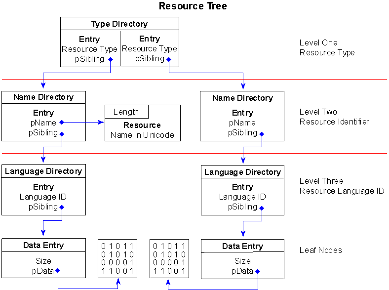
Figure 2. A simple resource tree structure
Figure 2 depicts a very simple resource tree containing only two resource objects, a menu, and a string table. Further, the menu and string table have only one item each. Yet, you can see how complicated the resource tree becomes--even with as few resources as this.
At the root of the tree, the first directory has one entry for each type of resource the file contains, no matter how many of each type there are. In Figure 2, there are two entries identified by the root, one for the menu and one for the string table. If there had been one or more dialog resources included in the file, the root node would have had one more entry and, consequently, another branch for the dialog resources.
The basic resource types are identified in the file WINUSER.H and are listed below:
WINUSER.H
/*
 * Predefined Resource Types
 */
#define RT_CURSOR           MAKEINTRESOURCE(1)
#define RT_BITMAP           MAKEINTRESOURCE(2)
#define RT_ICON             MAKEINTRESOURCE(3)
#define RT_MENU             MAKEINTRESOURCE(4)
#define RT_DIALOG           MAKEINTRESOURCE(5)
#define RT_STRING           MAKEINTRESOURCE(6)
#define RT_FONTDIR          MAKEINTRESOURCE(7)
#define RT_FONT             MAKEINTRESOURCE(8)
#define RT_ACCELERATOR      MAKEINTRESOURCE(9)
#define RT_RCDATA           MAKEINTRESOURCE(10)
#define RT_MESSAGETABLE     MAKEINTRESOURCE(11)
At the top level of the tree, the MAKEINTRESOURCE values listed above are placed in the Name field of each type entry, identifying the different resources by type.
Each of the entries in the root directory points to a sibling node in the second level of the tree. These nodes are directories, too, each having their own entries. At this level, the directories are used to identify the name of each resource within a given type. If you had multiple menus defined in your application, there would be an entry for each one here at the second level of the tree.
As you are probably already aware, resources can be identified by name or by integer. They are distinguished in this level of the tree via the Name field in the directory structure. If the most significant bit of the Name field is set, the other 31 bits are used as an offset to an IMAGE_RESOURCE_DIR_STRING_U structure.
WINNT.H
typedef struct _IMAGE_RESOURCE_DIR_STRING_U {
    USHORT  Length;
    WCHAR   NameString[ 1 ];
} IMAGE_RESOURCE_DIR_STRING_U, *PIMAGE_RESOURCE_DIR_STRING_U;
This structure is simply a 2-byte Length field followed by Length UNICODE characters.
On the other hand, if the most significant bit of the Name field is clear, the lower 31 bits are used to represent the integer ID of the resource. Figure 2 shows the menu resource as a named resource and the string table as an ID resource.
If there were two menu resources, one identified by name and one by resource, they would both have entries immediately after the menu resource directory. The named resource entry would appear first, followed by the integer-identified resource. The directory fields NumberOfNamedEntries and NumberOfIdEntries would each contain the value 1, indicating the presence of one entry.
Below level two, the resource tree does not branch out any further. Level one branches into directories representing each type of resource, and level two branches into directories representing each resource by identifier. Level three maps a one-to-one correspondence between the individually identified resources and their respective language IDs. To indicate the language ID of a resource, the Name field of the directory entry structure is used to indicate both the primary language and sublanguage ID for the resource. The Win32 SDK for Windows NT lists the default value resources. For the value 0x0409, 0x09 represents the primary language as LANG_ENGLISH, and 0x04 is defined as SUBLANG_ENGLISH_CAN for the sublanguage. The entire set of language IDs is defined in the file WINNT.H, included as part of the Win32 SDK for Windows NT.
Since the language ID node is the last directory node in the tree, the OffsetToData field in the entry structure is an offset to a leaf node--the IMAGE_RESOURCE_DATA_ENTRY structure mentioned earlier.
Referring back to Figure 2, you can see one data entry node for each language directory entry. This node simply indicates the size of the resource data and the relative virtual address where the resource data is located.
One advantage to having so much structure to the resource data section, .rsrc, is that you can glean a great deal of information from the section without accessing the resources themselves. For example, you can find out how many there are of each type of resource, what resources--if any--use a particular language ID, whether a particular resource exists or not, and the size of individual types of resources. To demonstrate how to make use of this information, the following function shows how to determine the different types of resources a file includes:
PEFILE.C
int     WINAPI GetListOfResourceTypes (
    LPVOID    lpFile,
    HANDLE    hHeap,
    char      **pszResTypes)
{
    PIMAGE_RESOURCE_DIRECTORY          prdRoot;
    PIMAGE_RESOURCE_DIRECTORY_ENTRY    prde;
    char                               *pMem;
    int                                nCnt, i;


    /* Get root directory of resource tree. */
    if ((prdRoot = PIMAGE_RESOURCE_DIRECTORY)ImageDirectoryOffset
           (lpFile, IMAGE_DIRECTORY_ENTRY_RESOURCE)) == NULL)
        return 0;

    /* Allocate enough space from heap to cover all types. */
    nCnt = prdRoot->NumberOfIdEntries * (MAXRESOURCENAME + 1);
    *pszResTypes = (char *)HeapAlloc (hHeap,
                                      HEAP_ZERO_MEMORY,
                                      nCnt);
    if ((pMem = *pszResTypes) == NULL)
        return 0;

    /* Set pointer to first resource type entry. */
    prde = (PIMAGE_RESOURCE_DIRECTORY_ENTRY)((DWORD)prdRoot +
               sizeof (IMAGE_RESOURCE_DIRECTORY));

    /* Loop through all resource directory entry types. */
    for (i=0; i<prdRoot->NumberOfIdEntries; i++)
        {
        if (LoadString (hDll, prde->Name, pMem, MAXRESOURCENAME))
            pMem += strlen (pMem) + 1;

        prde++;
        }

    return nCnt;
}
This function returns a list of resource type names in the string identified by pszResTypes. Notice that, at the heart of this function, LoadString is called using the Name field of each resource type directory entry as the string ID. If you look in the PEFILE.RC, you'll see that I defined a series of resource type strings whose IDs are defined the same as the type specifiers in the directory entries. There is also a function in PEFILE.DLL that returns the total number of resource objects in the .rsrc section. It would be rather easy to expand on these functions or write new functions that extracted other information from this section.
Export data section, .edata
The .edata section contains export data for an application or DLL. When present, this section contains an export directory for getting to the export information.
WINNT.H
typedef struct _IMAGE_EXPORT_DIRECTORY {
    ULONG   Characteristics;
    ULONG   TimeDateStamp;
    USHORT  MajorVersion;
    USHORT  MinorVersion;
    ULONG   Name;
    ULONG   Base;
    ULONG   NumberOfFunctions;
    ULONG   NumberOfNames;
    PULONG  *AddressOfFunctions;
    PULONG  *AddressOfNames;
    PUSHORT *AddressOfNameOrdinals;
} IMAGE_EXPORT_DIRECTORY, *PIMAGE_EXPORT_DIRECTORY;
The Name field in the export directory identifies the name of the executable module. NumberOfFunctions and NumberOfNames fields indicate how many functions and function names are being exported from the module.
The AddressOfFunctions field is an offset to a list of exported function entry points. The AddressOfNames field is the address of an offset to the beginning of a null-separated list of exported function names. AddressOfNameOrdinals is an offset to a list of ordinal values (each 2 bytes long) for the same exported functions.
The three AddressOf... fields are relative virtual addresses into the address space of a process once the module has been loaded. Once the module is loaded, the relative virtual address should be added to the module base address to get the exact location in the address space of the process. Before the file is loaded, however, the address can be determined by subtracting the section header virtual address (VirtualAddress) from the given field address, adding the section body offset (PointerToRawData) to the result, and then using this value as an offset into the image file. The following example illustrates this technique:
PEFILE.C
int  WINAPI GetExportFunctionNames (
    LPVOID    lpFile,
    HANDLE    hHeap,
    char      **pszFunctions)
{
    IMAGE_SECTION_HEADER       sh;
    PIMAGE_EXPORT_DIRECTORY    ped;
    char                       *pNames, *pCnt;
    int                        i, nCnt;

    /* Get section header and pointer to data directory
       for .edata section. */
    if ((ped = (PIMAGE_EXPORT_DIRECTORY)ImageDirectoryOffset
            (lpFile, IMAGE_DIRECTORY_ENTRY_EXPORT)) == NULL)
        return 0;
    GetSectionHdrByName (lpFile, &sh, ".edata");

    /* Determine the offset of the export function names. */
    pNames = (char *)(*(int *)((int)ped->AddressOfNames -
                               (int)sh.VirtualAddress   +
                               (int)sh.PointerToRawData +
                               (int)lpFile)    -
                      (int)sh.VirtualAddress   +
                      (int)sh.PointerToRawData +
                      (int)lpFile);

    /* Figure out how much memory to allocate for all strings. */
    pCnt = pNames;
    for (i=0; i<(int)ped->NumberOfNames; i++)
        while (*pCnt++);
    nCnt = (int)(pCnt. pNames);

    /* Allocate memory off heap for function names. */
    *pszFunctions = HeapAlloc (hHeap, HEAP_ZERO_MEMORY, nCnt);

    /* Copy all strings to buffer. */
    CopyMemory ((LPVOID)*pszFunctions, (LPVOID)pNames, nCnt);

    return nCnt;
}
Notice that in this function the variable pNames is assigned by determining first the address of the offset and then the actual offset location. Both the address of the offset and the offset itself are relative virtual addresses and must be translated before being used, as the function demonstrates. You could write a similar function to determine the ordinal values or entry points of the functions, but why bother when I already did this for you? The GetNumberOfExportedFunctions, GetExportFunctionEntryPoints, and GetExportFunctionOrdinals functions also exist in the PEFILE.DLL.
Import data section, .idata
The .idata section is import data, including the import directory and import address name table. Although an IMAGE_DIRECTORY_ENTRY_IMPORT directory is defined, no corresponding import directory structure is included in the file WINNT.H. Instead, there are several other structures called IMAGE_IMPORT_BY_NAME, IMAGE_THUNK_DATA, and IMAGE_IMPORT_DESCRIPTOR. Personally, I couldn't make heads or tails of how these structures are supposed to correlate to the .idata section, so I spent several hours deciphering the .idata section body and came up with a much simpler structure. I named this structure IMAGE_IMPORT_MODULE_DIRECTORY.
PEFILE.H
typedef struct tagImportDirectory
    {
    DWORD    dwRVAFunctionNameList;
    DWORD    dwUseless1;
    DWORD    dwUseless2;
    DWORD    dwRVAModuleName;
    DWORD    dwRVAFunctionAddressList;
    }IMAGE_IMPORT_MODULE_DIRECTORY,
     * PIMAGE_IMPORT_MODULE_DIRECTORY;
Unlike the data directories of other sections, this one repeats one after another for each imported module in the file. Think of it as an entry in a list of module data directories, rather than a data directory to the entire section of data. Each entry is a directory to the import information for a specific module.
One of the fields in the IMAGE_IMPORT_MODULE_DIRECTORY structure is dwRVAModuleName, a relative virtual address pointing to the name of the module. There are also two dwUselessparameters in the structure that serve as padding to keep the structure aligned properly within the section. The PE file format specification mentions something about import flags, a time/date stamp, and major/minor versions, but these two fields remained empty throughout my experimentation, so I still consider them useless.
Based on the definition of this structure, you can retrieve the names of modules and all functions in each module that are imported by an executable file. The following function demonstrates how to retrieve all the module names imported by a particular PE file:
PEFILE.C
int  WINAPI GetImportModuleNames (
    LPVOID    lpFile,
    HANDLE    hHeap,
    char      **pszModules)
{
    PIMAGE_IMPORT_MODULE_DIRECTORY  pid;
    IMAGE_SECTION_HEADER            idsh;
    BYTE                            *pData;
    int                             nCnt = 0, nSize = 0, i;
    char                            *pModule[1024];
    char                            *psz;

    pid = (PIMAGE_IMPORT_MODULE_DIRECTORY)ImageDirectoryOffset
             (lpFile, IMAGE_DIRECTORY_ENTRY_IMPORT);
    pData = (BYTE *)pid;

    /* Locate section header for ".idata" section. */
    if (!GetSectionHdrByName (lpFile, &idsh, ".idata"))
        return 0;

    /* Extract all import modules. */
    while (pid->dwRVAModuleName)
        {
        /* Allocate buffer for absolute string offsets. */
        pModule[nCnt] = (char *)(pData +
               (pid->dwRVAModuleName-idsh.VirtualAddress));
        nSize += strlen (pModule[nCnt]) + 1;

        /* Increment to the next import directory entry. */
        pid++;
        nCnt++;
        }

    /* Copy all strings to one chunk of heap memory. */
    *pszModules = HeapAlloc (hHeap, HEAP_ZERO_MEMORY, nSize);
    psz = *pszModules;
    for (i=0; i<nCnt; i++)
        {
        strcpy (psz, pModule[i]);
        psz += strlen (psz) + 1;
        }

    return nCnt;
}
The function is pretty straightforward. However, one thing is worth pointing out--notice the while loop. This loop is terminated when pid->dwRVAModuleName is 0. Implied here is that at the end of the list of IMAGE_IMPORT_MODULE_DIRECTORY structures is a null structure that has a value of 0 for at least the dwRVAModuleName field. This is the behavior I observed in my experimentation with the file and later confirmed in the PE file format specification.
The first field in the structure, dwRVAFunctionNameList, is a relative virtual address to a list of relative virtual addresses that each point to the function names within the file. As shown in the following data, the module and function names of all imported modules are listed in the .idata section data:
E6A7 0000 F6A7 0000  08A8 0000 1AA8 0000  ................
28A8 0000 3CA8 0000  4CA8 0000 0000 0000  (...<...L.......
0000 4765 744F 7065  6E46 696C 654E 616D  ..GetOpenFileNam
6541 0000 636F 6D64  6C67 3332 2E64 6C6C  eA..comdlg32.dll
0000 2500 4372 6561  7465 466F 6E74 496E  ..%.CreateFontIn
6469 7265 6374 4100  4744 4933 322E 646C  directA.GDI32.dl
6C00 A000 4765 7444  6576 6963 6543 6170  l...GetDeviceCap
7300 C600 4765 7453  746F 636B 4F62 6A65  s...GetStockObje
6374 0000 D500 4765  7454 6578 744D 6574  ct....GetTextMet
7269 6373 4100 1001  5365 6C65 6374 4F62  ricsA...SelectOb
6A65 6374 0000 1601  5365 7442 6B43 6F6C  ject....SetBkCol
6F72 0000 3501 5365  7454 6578 7443 6F6C  or..5.SetTextCol
6F72 0000 4501 5465  7874 4F75 7441 0000  or..E.TextOutA..
The above data is a portion taken from the .idata section of the EXEVIEW.EXE sample application. This particular section represents the beginning of the list of import module and function names. If you begin examining the right section part of the data, you should recognize the names of familiar Win32 API functions and the module names they are found in. Reading from the top down, you get GetOpenFileNameA, followed by the module name COMDLG32.DLL. Shortly after that, you get CreateFontIndirectA, followed by the module GDI32.DLL and then the functions GetDeviceCaps, GetStockObject, GetTextMetrics, and so forth.
This pattern repeats throughout the .idata section. The first module name is COMDLG32.DLL and the second is GDI32.DLL. Notice that only one function is imported from the first module, while many functions are imported from the second module. In both cases, the function names and the module name to which they belong are ordered such that a function name appears first, followed by the module name and then by the rest of the function names, if any.
The following function demonstrates how to retrieve the function names for a specific module:
PEFILE.C
int  WINAPI GetImportFunctionNamesByModule (
    LPVOID    lpFile,
    HANDLE    hHeap,
    char      *pszModule,
    char      **pszFunctions)
{
    PIMAGE_IMPORT_MODULE_DIRECTORY  pid;
    IMAGE_SECTION_HEADER     idsh;
    DWORD                    dwBase;
    int                      nCnt = 0, nSize = 0;
    DWORD                    dwFunction;
    char                     *psz;


    /* Locate section header for ".idata" section. */
    if (!GetSectionHdrByName (lpFile, &idsh, ".idata"))
        return 0;

    pid = (PIMAGE_IMPORT_MODULE_DIRECTORY)ImageDirectoryOffset
             (lpFile, IMAGE_DIRECTORY_ENTRY_IMPORT);

    dwBase = ((DWORD)pid. idsh.VirtualAddress);

    /* Find module's pid. */
    while (pid->dwRVAModuleName &&
           strcmp (pszModule,
                  (char *)(pid->dwRVAModuleName+dwBase)))
        pid++;

    /* Exit if the module is not found. */
    if (!pid->dwRVAModuleName)
        return 0;

    /* Count number of function names and length of strings. */
    dwFunction = pid->dwRVAFunctionNameList;
    while (dwFunction                      &&
           *(DWORD *)(dwFunction + dwBase) &&
           *(char *)((*(DWORD *)(dwFunction + dwBase)) +
            dwBase+2))
        {
        nSize += strlen ((char *)((*(DWORD *)(dwFunction +
             dwBase)) + dwBase+2)) + 1;
        dwFunction += 4;
        nCnt++;
        }

    /* Allocate memory off heap for function names. */
    *pszFunctions = HeapAlloc (hHeap, HEAP_ZERO_MEMORY, nSize);
    psz = *pszFunctions;

    /* Copy function names to memory pointer. */
    dwFunction = pid->dwRVAFunctionNameList;
    while (dwFunction                      &&
           *(DWORD *)(dwFunction + dwBase) &&
           *((char *)((*(DWORD *)(dwFunction + dwBase)) +
            dwBase+2)))
        {
        strcpy (psz, (char *)((*(DWORD *)(dwFunction + dwBase)) +
                dwBase+2));
        psz += strlen((char *)((*(DWORD *)(dwFunction + dwBase))+
                dwBase+2)) + 1;
        dwFunction += 4;
        }

    return nCnt;
}
Like the GetImportModuleNames function, this function relies on the end of each list of information to have a zeroed entry. In this case, the list of function names ends with one that is zero.
The final field, dwRVAFunctionAddressList, is a relative virtual address to a list of virtual addresses that will be placed in the section data by the loader when the file is loaded. Before the file is loaded, however, these virtual addresses are replaced by relative virtual addresses that correspond exactly to the list of function names. So before the file is loaded, there are two identical lists of relative virtual addresses pointing to imported function names.
Debug information section, .debug
Debug information is initially placed in the .debug section. The PE file format also supports separate debug files (normally identified with a .DBG extension) as a means of collecting debug information in a central location. The debug section contains the debug information, but the debug directories live in the .rdata section mentioned earlier. Each of those directories references debug information in the .debug section. The debug directory structure is defined as an IMAGE_DEBUG_DIRECTORY, as follows:
WINNT.H
typedef struct _IMAGE_DEBUG_DIRECTORY {
    ULONG   Characteristics;
    ULONG   TimeDateStamp;
    USHORT  MajorVersion;
    USHORT  MinorVersion;
    ULONG   Type;
    ULONG   SizeOfData;
    ULONG   AddressOfRawData;
    ULONG   PointerToRawData;
} IMAGE_DEBUG_DIRECTORY, *PIMAGE_DEBUG_DIRECTORY;
The section is divided into separate portions of data representing different types of debug information. For each one there is a debug directory described above. The different types of debug information are listed below:
WINNT.H
#define IMAGE_DEBUG_TYPE_UNKNOWN          0
#define IMAGE_DEBUG_TYPE_COFF             1
#define IMAGE_DEBUG_TYPE_CODEVIEW         2
#define IMAGE_DEBUG_TYPE_FPO              3
#define IMAGE_DEBUG_TYPE_MISC             4
The Type field in each directory indicates which type of debug information the directory represents. As you can see in the list above, the PE file format supports many different types of debug information, as well as some other informational fields. Of those, the IMAGE_DEBUG_TYPE_MISC information is unique. This information was added to represent miscellaneous information about the executable image that could not be added to any of the more structured data sections in the PE file format. This is the only location in the image file where the image name is sure to appear. If an image exports information, the export data section will also include the image name.
Each type of debug information has its own header structure that defines its data. Each of these is listed in the file WINNT.H. One nice thing about the IMAGE_DEBUG_DIRECTORY structure is that it includes two fields that identify the debug information. The first of these, AddressOfRawData, is the relative virtual address of the data once the file is loaded. The other,PointerToRawData, is an actual offset within the PE file, where the data is located. This makes it easy to locate specific debug information.
As a last example, consider the following function, which extracts the image name from the IMAGE_DEBUG_MISC structure:
PEFILE.C
int    WINAPI RetrieveModuleName (
    LPVOID    lpFile,
    HANDLE    hHeap,
    char      **pszModule)
{

    PIMAGE_DEBUG_DIRECTORY    pdd;
    PIMAGE_DEBUG_MISC         pdm = NULL;
    int                       nCnt;

    if (!(pdd = (PIMAGE_DEBUG_DIRECTORY)ImageDirectoryOffset
               (lpFile, IMAGE_DIRECTORY_ENTRY_DEBUG)))
        return 0;

    while (pdd->SizeOfData)
        {
        if (pdd->Type == IMAGE_DEBUG_TYPE_MISC)
            {
            pdm = (PIMAGE_DEBUG_MISC)
                ((DWORD)pdd->PointerToRawData + (DWORD)lpFile);

            nCnt = lstrlen (pdm->Data)*(pdm->Unicode?2:1);
            *pszModule = (char *)HeapAlloc (hHeap,
                                            HEAP_ZERO_MEMORY,
                                            nCnt+1;
            CopyMemory (*pszModule, pdm->Data, nCnt);

            break;
            }

        pdd ++;
        }

    if (pdm != NULL)
        return nCnt;
    else
        return 0;
}
As you can see, the structure of the debug directory makes it relatively easy to locate a specific type of debug information. Once the IMAGE_DEBUG_MISC structure is located, extracting the image name is as simple as invoking the CopyMemory function.
As mentioned above, debug information can be stripped into separate .DBG files. The Windows NT SDK includes a utility called REBASE.EXE that serves this purpose. For example, in the following statement an executable image named TEST.EXE is being stripped of debug information:
rebase -b 40000 -x c:\samples\testdir test.exe
The debug information is placed in a new file called TEST.DBG and located in the path specified, in this case c:\samples\testdir. The file begins with a singleIMAGE_SEPARATE_DEBUG_HEADER structure, followed by a copy of the section headers that exist in the stripped executable image. Then the .debug section data follows the section headers. So, right after the section headers are the series of IMAGE_DEBUG_DIRECTORY structures and their associated data. The debug information itself retains the same structure as described above for normal image file debug information.
Summary of the PE File Format
The PE file format for Windows NT introduces a completely new structure to developers familiar with the Windows and MS-DOS environments. Yet developers familiar with the UNIX environment will find that the PE file format is similar to, if not based on, the COFF specification.
The entire format consists of an MS-DOS MZ header, followed by a real-mode stub program, the PE file signature, the PE file header, the PE optional header, all of the section headers, and finally, all of the section bodies.
The optional header ends with an array of data directory entries that are relative virtual addresses to data directories contained within section bodies. Each data directory indicates how a specific section body's data is structured.
The PE file format has eleven predefined sections, as is common to applications for Windows NT, but each application can define its own unique sections for code and data.
The .debug predefined section also has the capability of being stripped from the file into a separate debug file. If so, a special debug header is used to parse the debug file, and a flag is specified in the PE file header to indicate that the debug data has been stripped.
PEFILE.DLL Function Descriptions
PEFILE.DLL consists mainly of functions that either retrieve an offset into a given PE file or copy a portion of the file data to a specific structure. Each function has a single requirement--the first parameter is a pointer to the beginning of the PE file. That is, the file must first be memory-mapped into the address space of your process, and the base location of the file mapping is the value lpFile that you pass as the first parameter to every function.
The function names are meant to be self-explanatory, and each function is listed with a brief comment describing its purpose. If, after reading through the list of functions, you cannot determine what a function is for, refer to the EXEVIEW.EXE sample application to find an example of how the function is used. The following list of function prototypes can also be found in PEFILE.H:
PEFILE.H
/* Retrieve a pointer offset to the MS-DOS MZ header. */
BOOL WINAPI GetDosHeader (LPVOID, PIMAGE_DOS_HEADER);

/* Determine the type of an .EXE file. */
DWORD WINAPI ImageFileType (LPVOID);

/* Retrieve a pointer offset to the PE file header. */
BOOL WINAPI GetPEFileHeader (LPVOID, PIMAGE_FILE_HEADER);

/* Retrieve a pointer offset to the PE optional header .*/
BOOL WINAPI GetPEOptionalHeader (LPVOID,
                                  PIMAGE_OPTIONAL_HEADER);

/* Return the address of the module entry point. */
LPVOID WINAPI GetModuleEntryPoint (LPVOID);

/* Return a count of the number of sections in the file. */
int  WINAPI NumOfSections (LPVOID);

/* Return the desired base address of the executable when
   it is loaded into a process's address space. */
LPVOID WINAPI GetImageBase (LPVOID);

/* Determine the location within the file of a specific
   image data directory.  */
LPVOID WINAPI ImageDirectoryOffset (LPVOID, DWORD);

/* Function retrieve names of all the sections in the file. */
int WINAPI GetSectionNames (LPVOID, HANDLE, char **);

/* Copy the section header information for a specific section. */
BOOL WINAPI GetSectionHdrByName (LPVOID,
                                  PIMAGE_SECTION_HEADER, char *);

/* Get null-separated list of import module names. */
int WINAPI GetImportModuleNames (LPVOID, HANDLE, char  **);

/* Get null-separated list of import functions for a module. */
int WINAPI GetImportFunctionNamesByModule (LPVOID, HANDLE,
                                           char *, char  **);

/* Get null-separated list of exported function names. */
int WINAPI GetExportFunctionNames (LPVOID, HANDLE, char **);

/* Get number of exported functions. */
int WINAPI GetNumberOfExportedFunctions (LPVOID);

/* Get list of exported function virtual address entry points. */
LPVOID WINAPI GetExportFunctionEntryPoints (LPVOID);

/* Get list of exported function ordinal values. */
LPVOID WINAPI GetExportFunctionOrdinals (LPVOID);

/* Determine total number of resource objects. */
int WINAPI GetNumberOfResources (LPVOID);

/* Return list of all resource object types used in file. */
int WINAPI GetListOfResourceTypes (LPVOID, HANDLE, char **);

/* Determine if debug information has been removed from file. */
BOOL WINAPI IsDebugInfoStripped (LPVOID);

/* Get name of image file. */
int WINAPI RetrieveModuleName (LPVOID, HANDLE, char **);

/* Function determines if the file is a valid debug file. */
BOOL WINAPI IsDebugFile (LPVOID);

/* Function returns debug header from debug file. */
BOOL WINAPI GetSeparateDebugHeader(LPVOID,
                                   PIMAGE_SEPARATE_DEBUG_HEADER);
In addition to the functions listed above, the macros mentioned earlier in this article are also defined in the PEFILE.H file. The complete list is as follows:
/* Offset to PE file signature                              */
#define NTSIGNATURE(a) ((LPVOID)((BYTE *)a                +  \
                        ((PIMAGE_DOS_HEADER)a)->e_lfanew))

/* MS-OS header identifies the NT PEFile signature dword;
   the PEFILE header exists just after that dword.           */
#define PEFHDROFFSET(a) ((LPVOID)((BYTE *)a               +  \
                         ((PIMAGE_DOS_HEADER)a)->e_lfanew +  \
                             SIZE_OF_NT_SIGNATURE))

/* PE optional header is immediately after PEFile header.    */
#define OPTHDROFFSET(a) ((LPVOID)((BYTE *)a               +  \
                         ((PIMAGE_DOS_HEADER)a)->e_lfanew +  \
                           SIZE_OF_NT_SIGNATURE           +  \
                           sizeof (IMAGE_FILE_HEADER)))

/* Section headers are immediately after PE optional header. */
#define SECHDROFFSET(a) ((LPVOID)((BYTE *)a               +  \
                         ((PIMAGE_DOS_HEADER)a)->e_lfanew +  \
                           SIZE_OF_NT_SIGNATURE           +  \
                           sizeof (IMAGE_FILE_HEADER)     +  \
                           sizeof (IMAGE_OPTIONAL_HEADER)))
To use PEFILE.DLL, simply include the header file PEFILE.H and link the DLL to your application. All of the functions are mutually exclusive functions, but some were written as much to support others as for the information they provide. For example, the function GetSectionNames is useful for getting the exact names of all sections. Yet to be able to retrieve the section header for a unique section name (one defined by the application developer during compile), you would first have to get the list of names and then call the function GetSectionHeaderByName with the exact name of the section. Enjoy!
Peering Inside the PE: A Tour of the Win32 Portable Executable File Format
Matt Pietrek
March 1994
Matt Pietrek is the author of Windows Internals (Addison-Wesley, 1993). He works at Nu-Mega Technologies Inc., and can be reached via CompuServe: 71774,362
This article is reproduced from the March 1994 issue of Microsoft Systems Journal. Copyright © 1994 by Miller Freeman, Inc. All rights are reserved. No part of this article may be reproduced in any fashion (except in brief quotations used in critical articles and reviews) without the prior consent of Miller Freeman.
To contact Miller Freeman regarding subscription information, call (800) 666-1084 in the U.S., or (303) 447-9330 in all other countries. For other inquiries, call (415) 358-9500.
The format of an operating system's executable file is in many ways a mirror of the operating system. Although studying an executable file format isn't usually high on most programmers' list of things to do, a great deal of knowledge can be gleaned this way. In this article, I'll give a tour of the Portable Executable (PE) file format that Microsoft has designed for use by all their Win32®-based systems: Windows NT®, Win32s™, and Windows® 95. The PE format plays a key role in all of Microsoft's operating systems for the foreseeable future, including Windows 2000. If you use Win32s or Windows NT, you're already using PE files. Even if you program only for Windows 3.1 using Visual C++®, you're still using PE files (the 32-bit MS-DOS® extended components of Visual C++ use this format). In short, PEs are already pervasive and will become unavoidable in the near future. Now is the time to find out what this new type of executable file brings to the operating system party.
I'm not going to make you stare at endless hex dumps and chew over the significance of individual bits for pages on end. Instead, I'll present the concepts embedded in the PE file format and relate them to things you encounter everyday. For example, the notion of thread local variables, as in
declspec(thread) int i;
drove me crazy until I saw how it was implemented with elegant simplicity in the executable file. Since many of you are coming from a background in 16-bit Windows, I'll correlate the constructs of the Win32 PE file format back to their 16-bit NE file format equivalents.
In addition to a different executable format, Microsoft also introduced a new object module format produced by their compilers and assemblers. This new OBJ file format has many things in common with the PE executable format. I've searched in vain to find any documentation on the new OBJ file format. So I deciphered it on my own, and will describe parts of it here in addition to the PE format.
It's common knowledge that Windows NT has a VAX® VMS® and UNIX® heritage. Many of the Windows NT creators designed and coded for those platforms before coming to Microsoft. When it came time to design Windows NT, it was only natural that they tried to minimize their bootstrap time by using previously written and tested tools. The executable and object module format that these tools produced and worked with is called COFF (an acronym for Common Object File Format). The relative age of COFF can be seen by things such as fields specified in octal format. The COFF format by itself was a good starting point, but needed to be extended to meet all the needs of a modern operating system like Windows NT or Windows 95. The result of this updating is the Portable Executable format. It's called "portable" because all the implementations of Windows NT on various platforms (x86, MIPS®, Alpha, and so on) use the same executable format. Sure, there are differences in things like the binary encodings of CPU instructions. The important thing is that the operating system loader and programming tools don't have to be completely rewritten for each new CPU that arrives on the scene.
The strength of Microsoft's commitment to get Windows NT up and running quickly is evidenced by the fact that they abandoned existing 32-bit tools and file formats. Virtual device drivers written for 16-bit Windows were using a different 32-bit file layout—the LE format—long before Windows NT appeared on the scene. More important than that is the shift of OBJ formats. Prior to the Windows NT C compiler, all Microsoft compilers used the Intel OMF (Object Module Format) specification. As mentioned earlier, the Microsoft compilers for Win32 produce COFF-format OBJ files. Some Microsoft competitors such as Borland and Symantec have chosen to forgo the COFF format OBJs and stick with the Intel OMF format. The upshot of this is that companies producing OBJs or LIBs for use with multiple compilers will need to go back to distributing separate versions of their products for different compilers (if they weren't already).
The PE format is documented (in the loosest sense of the word) in the WINNT.H header file. About midway through WINNT.H is a section titled "Image Format." This section starts out with small tidbits from the old familiar MS-DOS MZ format and NE format headers before moving into the newer PE information. WINNT.H provides definitions of the raw data structures used by PE files, but contains only a few useful comments to make sense of what the structures and flags mean. Whoever wrote the header file for the PE format (the name Michael J. O'Leary keeps popping up) is certainly a believer in long, descriptive names, along with deeply nested structures and macros. When coding with WINNT.H, it's not uncommon to have expressions like this:
pNTHeader->
OptionalHeader.DataDirectory[IMAGE_DIRECTORY_ENTRY_DEBUG].VirtualAddress;
To help make logical sense of the information in WINNT.H, read the Portable Executable and Common Object File Format Specification, available on MSDN Library quarterly CD-ROM releases up to and including October 2001.
Turning momentarily to the subject of COFF-format OBJs, the WINNT.H header file includes structure definitions and typedefs for COFF OBJ and LIB files. Unfortunately, I've been unable to find any documentation on this similar to that for the executable file mentioned above. Since PE files and COFF OBJ files are so similar, I decided that it was time to bring these files out into the light and document them as well.
Beyond just reading about what PE files are composed of, you'll also want to dump some PE files to see these concepts for yourself. If you use Microsoft® tools for Win32-based development, the DUMPBIN program will dissect and output PE files and COFF OBJ/LIB files in readable form. Of all the PE file dumpers, DUMPBIN is easily the most comprehensive. It even has a nifty option to disassemble the code sections in the file it's taking apart. Borland users can use TDUMP to view PE executable files, but TDUMP doesn't understand the COFF OBJ files. This isn't a big deal since the Borland compiler doesn't produce COFF-format OBJs in the first place.
I've written a PE and COFF OBJ file dumping program, PEDUMP (see Table 1), that I think provides more understandable output than DUMPBIN. Although it doesn't have a disassembler or work with LIB files, it is otherwise functionally equivalent to DUMPBIN, and adds a few new features to make it worth considering. The source code for PEDUMP is available on any MSJ bulletin board, so I won't list it here in its entirety. Instead, I'll show sample output from PEDUMP to illustrate the concepts as I describe them.
Table 1. PEDUMP.C
//--------------------
// PROGRAM: PEDUMP
// FILE:    PEDUMP.C
// AUTHOR:  Matt Pietrek - 1993
//--------------------
#include <windows.h>
#include <stdio.h>
#include "objdump.h"
#include "exedump.h"
#include "extrnvar.h"

// Global variables set here, and used in EXEDUMP.C and OBJDUMP.C
BOOL fShowRelocations = FALSE;
BOOL fShowRawSectionData = FALSE;
BOOL fShowSymbolTable = FALSE;
BOOL fShowLineNumbers = FALSE;

char HelpText[] =
"PEDUMP - Win32/COFF .EXE/.OBJ file dumper - 1993 Matt Pietrek\n\n"
"Syntax: PEDUMP [switches] filename\n\n"
"  /A    include everything in dump\n"
"  /H    include hex dump of sections\n"
"  /L    include line number information\n"
"  /R    show base relocations\n"
"  /S    show symbol table\n";

// Open up a file, memory map it, and call the appropriate dumping routine
void DumpFile(LPSTR filename)
{
    HANDLE hFile;
    HANDLE hFileMapping;
    LPVOID lpFileBase;
    PIMAGE_DOS_HEADER dosHeader;

    hFile = CreateFile(filename, GENERIC_READ, FILE_SHARE_READ, NULL,
                        OPEN_EXISTING, FILE_ATTRIBUTE_NORMAL, 0);

    if ( hFile = = INVALID_HANDLE_VALUE )
    {   printf("Couldn't open file with CreateFile()\n");
        return; }

    hFileMapping = CreateFileMapping(hFile, NULL, PAGE_READONLY, 0, 0, NULL);
    if ( hFileMapping = = 0 )
    {   CloseHandle(hFile);
        printf("Couldn't open file mapping with CreateFileMapping()\n");
        return; }

    lpFileBase = MapViewOfFile(hFileMapping, FILE_MAP_READ, 0, 0, 0);
    if ( lpFileBase = = 0 )
    {
        CloseHandle(hFileMapping);
        CloseHandle(hFile);
        printf("Couldn't map view of file with MapViewOfFile()\n");
        return;
    }

    printf("Dump of file %s\n\n", filename);

    dosHeader = (PIMAGE_DOS_HEADER)lpFileBase;
    if ( dosHeader->e_magic = = IMAGE_DOS_SIGNATURE )
       { DumpExeFile( dosHeader ); }
    else if ( (dosHeader->e_magic = = 0x014C)    // Does it look like a i386
              && (dosHeader->e_sp = = 0) )        // COFF OBJ file???
    {
        // The two tests above aren't what they look like.  They're
        // really checking for IMAGE_FILE_HEADER.Machine = = i386 (0x14C)
        // and IMAGE_FILE_HEADER.SizeOfOptionalHeader = = 0;
        DumpObjFile( (PIMAGE_FILE_HEADER)lpFileBase );
    }
    else
        printf("unrecognized file format\n");
    UnmapViewOfFile(lpFileBase);
    CloseHandle(hFileMapping);
    CloseHandle(hFile);
}

// process all the command line arguments and return a pointer to
// the filename argument.
PSTR ProcessCommandLine(int argc, char *argv[])
{
    int i;

    for ( i=1; i < argc; i++ )
    {
        strupr(argv[i]);

        // Is it a switch character?
        if ( (argv[i][0] = = '-') || (argv[i][0] = = '/') )
        {
            if ( argv[i][1] = = 'A' )
            {   fShowRelocations = TRUE;
                fShowRawSectionData = TRUE;
                fShowSymbolTable = TRUE;
                fShowLineNumbers = TRUE; }
            else if ( argv[i][1] = = 'H' )
                fShowRawSectionData = TRUE;
            else if ( argv[i][1] = = 'L' )
                fShowLineNumbers = TRUE;
            else if ( argv[i][1] = = 'R' )
                fShowRelocations = TRUE;
            else if ( argv[i][1] = = 'S' )
                fShowSymbolTable = TRUE;
        }
        else    // Not a switch character.  Must be the filename
        {   return argv[i]; }
    }
}

int main(int argc, char *argv[])
{
    PSTR filename;

    if ( argc = = 1 )
    {   printf(    HelpText );
        return 1; }

    filename = ProcessCommandLine(argc, argv);
    if ( filename )
        DumpFile( filename );
    return 0;
}
Win32 and PE Basic Concepts
Let's go over a few fundamental ideas that permeate the design of a PE file (see Figure 1). I'll use the term "module" to mean the code, data, and resources of an executable file or DLL that have been loaded into memory. Besides code and data that your program uses directly, a module is also composed of the supporting data structures used by Windows to determine where the code and data is located in memory. In 16-bit Windows, the supporting data structures are in the module database (the segment referred to by an HMODULE). In Win32, these data structures are in the PE header, which I'll explain shortly.

The first important thing to know about PE files is that the executable file on disk is very similar to what the module will look like after Windows has loaded it. The Windows loader doesn't need to work extremely hard to create a process from the disk file. The loader uses the memory-mapped file mechanism to map the appropriate pieces of the file into the virtual address space. To use a construction analogy, a PE file is like a prefabricated home. It's essentially brought into place in one piece, followed by a small amount of work to wire it up to the rest of the world (that is, to connect it to its DLLs and so on). This same ease of loading applies to PE-format DLLs as well. Once the module has been loaded, Windows can effectively treat it like any other memory-mapped file.
This is in marked contrast to the situation in 16-bit Windows. The 16-bit NE file loader reads in portions of the file and creates completely different data structures to represent the module in memory. When a code or data segment needs to be loaded, the loader has to allocate a new segment from the global heap, find where the raw data is stored in the executable file, seek to that location, read in the raw data, and apply any applicable fixups. In addition, each 16-bit module is responsible for remembering all the selectors it's currently using, whether the segment has been discarded, and so on.
For Win32, all the memory used by the module for code, data, resources, import tables, export tables, and other required module data structures is in one contiguous block of memory. All you need to know in this situation is where the loader mapped the file into memory. You can easily find all the various pieces of the module by following pointers that are stored as part of the image.
Another idea you should be acquainted with is the Relative Virtual Address (RVA). Many fields in PE files are specified in terms of RVAs. An RVA is simply the offset of some item, relative to where the file is memory-mapped. For example, let's say the loader maps a PE file into memory starting at address 0x10000 in the virtual address space. If a certain table in the image starts at address 0x10464, then the table's RVA is 0x464.
(Virtual address 0x10464)-(base address 0x10000) = RVA 0x00464
To convert an RVA into a usable pointer, simply add the RVA to the base address of the module. The base address is the starting address of a memory-mapped EXE or DLL and is an important concept in Win32. For the sake of convenience, Windows NT and Windows 95 uses the base address of a module as the module's instance handle (HINSTANCE). In Win32, calling the base address of a module an HINSTANCE is somewhat confusing, because the term "instance handle" comes from 16-bit Windows. Each copy of an application in 16-bit Windows gets its own separate data segment (and an associated global handle) that distinguishes it from other copies of the application, hence the term instance handle. In Win32, applications don't need to be distinguished from one another because they don't share the same address space. Still, the term HINSTANCE persists to keep continuity between 16-bit Windows and Win32. What's important for Win32 is that you can call GetModuleHandle for any DLL that your process uses to get a pointer for accessing the module's components.
The final concept that you need to know about PE files is sections. A section in a PE file is roughly equivalent to a segment or the resources in an NE file. Sections contain either code or data. Unlike segments, sections are blocks of contiguous memory with no size constraints. Some sections contain code or data that your program declared and uses directly, while other data sections are created for you by the linker and librarian, and contain information vital to the operating system. In some descriptions of the PE format, sections are also referred to as objects. The term object has so many overloaded meanings that I'll stick to calling the code and data areas sections.
The PE Header
Like all other executable file formats, the PE file has a collection of fields at a known (or easy to find) location that define what the rest of the file looks like. This header contains information such as the locations and sizes of the code and data areas, what operating system the file is intended for, the initial stack size, and other vital pieces of information that I'll discuss shortly. As with other executable formats from Microsoft, this main header isn't at the very beginning of the file. The first few hundred bytes of the typical PE file are taken up by the MS-DOS stub. This stub is a tiny program that prints out something to the effect of "This program cannot be run in MS-DOS mode." So if you run a Win32-based program in an environment that doesn't support Win32, you'll get this informative error message. When the Win32 loader memory maps a PE file, the first byte of the mapped file corresponds to the first byte of the MS-DOS stub. That's right. With every Win32-based program you start up, you get an MS-DOS-based program loaded for free!
As in other Microsoft executable formats, you find the real header by looking up its starting offset, which is stored in the MS-DOS stub header. The WINNT.H file includes a structure definition for the MS-DOS stub header that makes it very easy to look up where the PE header starts. The e_lfanew field is a relative offset (or RVA, if you prefer) to the actual PE header. To get a pointer to the PE header in memory, just add that field's value to the image base:
// Ignoring typecasts and pointer conversion issues for clarity...
pNTHeader = dosHeader + dosHeader->e_lfanew;
Once you have a pointer to the main PE header, the fun can begin. The main PE header is a structure of type IMAGE_NT_HEADERS, which is defined in WINNT.H. This structure is composed of a DWORD and two substructures and is laid out as follows:
DWORD Signature;
IMAGE_FILE_HEADER FileHeader;
IMAGE_OPTIONAL_HEADER OptionalHeader;
The Signature field viewed as ASCII text is "PE\0\0". If after using the e_lfanew field in the MS-DOS header, you find an NE signature here rather than a PE, you're working with a 16-bit Windows NE file. Likewise, an LE in the signature field would indicate a Windows 3.x virtual device driver (VxD). An LX here would be the mark of a file for OS/2 2.0.
Following the PE signature DWORD in the PE header is a structure of type IMAGE_FILE_HEADER. The fields of this structure contain only the most basic information about the file. The structure appears to be unmodified from its original COFF implementations. Besides being part of the PE header, it also appears at the very beginning of the COFF OBJs produced by the Microsoft Win32 compilers. The fields of the IMAGE_FILE_HEADER are shown in Table 2.
Table 2. IMAGE_FILE_HEADER Fields
WORD Machine- The CPU that this file is intended for. The following CPU IDs are defined:
0x14d Intel i860 0x14c Intel I386 (same ID used for 486 and 586) 0x162 MIPS R3000 0x166 MIPS R4000 0x183 DEC Alpha AXP
WORD NumberOfSections- The number of sections in the file.
DWORD TimeDateStamp- The time that the linker (or compiler for an OBJ file) produced this file. This field holds the number of seconds since December 31st, 1969, at 4:00 P.M.
DWORD PointerToSymbolTable- The file offset of the COFF symbol table. This field is only used in OBJ files and PE files with COFF debug information. PE files support multiple debug formats, so debuggers should refer to the IMAGE_DIRECTORY_ENTRY_DEBUG entry in the data directory (defined later).
DWORD NumberOfSymbols- The number of symbols in the COFF symbol table. See above.
WORD SizeOfOptionalHeader- The size of an optional header that can follow this structure. In OBJs, the field is 0. In executables, it is the size of the IMAGE_OPTIONAL_HEADER structure that follows this structure.
WORD Characteristics- Flags with information about the file. Some important fields:
0x0001
There are no relocations in this file
0x0002
File is an executable image (not a OBJ or LIB)
0x2000
File is a dynamic-link library, not a program
Other fields are defined in WINNT.H
The third component of the PE header is a structure of type IMAGE_OPTIONAL_HEADER. For PE files, this portion certainly isn't optional. The COFF format allows individual implementations to define a structure of additional information beyond the standard IMAGE_FILE_HEADER. The fields in the IMAGE_OPTIONAL_HEADER are what the PE designers felt was critical information beyond the basic information in the IMAGE_FILE_HEADER.
All of the fields of the IMAGE_OPTIONAL_HEADER aren't necessarily important to know about (see Figure 4). The more important ones to be aware of are the ImageBase and the Subsystem fields. You can skim or skip the description of the fields.
Table 3. IMAGE_OPTIONAL_HEADER Fields
WORD Magic- Appears to be a signature WORD of some sort. Always appears to be set to 0x010B.
BYTE MajorLinkerVersionBYTE MinorLinkerVersion- The version of the linker that produced this file. The numbers should be displayed as decimal values, rather than as hex. A typical linker version is 2.23.
DWORD SizeOfCode- The combined and rounded-up size of all the code sections. Usually, most files only have one code section, so this field matches the size of the .text section.
DWORD SizeOfInitializedData- This is supposedly the total size of all the sections that are composed of initialized data (not including code segments.) However, it doesn't seem to be consistent with what appears in the file.
DWORD SizeOfUninitializedData- The size of the sections that the loader commits space for in the virtual address space, but that don't take up any space in the disk file. These sections don't need to have specific values at program startup, hence the term uninitialized data. Uninitialized data usually goes into a section called .bss.
DWORD AddressOfEntryPoint- The address where the loader will begin execution. This is an RVA, and usually can usually be found in the .text section.
DWORD BaseOfCode- The RVA where the file's code sections begin. The code sections typically come before the data sections and after the PE header in memory. This RVA is usually 0x1000 in Microsoft Linker-produced EXEs. Borland's TLINK32 looks like it adds the image base to the RVA of the first code section and stores the result in this field.
DWORD BaseOfData- The RVA where the file's data sections begin. The data sections typically come last in memory, after the PE header and the code sections.
DWORD ImageBase- When the linker creates an executable, it assumes that the file will be memory-mapped to a specific location in memory. That address is stored in this field, assuming a load address allows linker optimizations to take place. If the file really is memory-mapped to that address by the loader, the code doesn't need any patching before it can be run. In executables produced for Windows NT, the default image base is 0x10000. For DLLs, the default is 0x400000. In Windows 95, the address 0x10000 can't be used to load 32-bit EXEs because it lies within a linear address region shared by all processes. Because of this, Microsoft has changed the default base address for Win32 executables to 0x400000. Older programs that were linked assuming a base address of 0x10000 will take longer to load under Windows 95 because the loader needs to apply the base relocations.
DWORD SectionAlignment- When mapped into memory, each section is guaranteed to start at a virtual address that's a multiple of this value. For paging purposes, the default section alignment is 0x1000.
DWORD FileAlignment- In the PE file, the raw data that comprises each section is guaranteed to start at a multiple of this value. The default value is 0x200 bytes, probably to ensure that sections always start at the beginning of a disk sector (which are also 0x200 bytes in length). This field is equivalent to the segment/resource alignment size in NE files. Unlike NE files, PE files typically don't have hundreds of sections, so the space wasted by aligning the file sections is almost always very small.
WORD MajorOperatingSystemVersionWORD MinorOperatingSystemVersion- The minimum version of the operating system required to use this executable. This field is somewhat ambiguous since the subsystem fields (a few fields later) appear to serve a similar purpose. This field defaults to 1.0 in all Win32 EXEs to date.
WORD MajorImageVersionWORD MinorImageVersion- A user-definable field. This allows you to have different versions of an EXE or DLL. You set these fields via the linker /VERSION switch. For example, "LINK /VERSION:2.0 myobj.obj".
WORD MajorSubsystemVersionWORD MinorSubsystemVersion- Contains the minimum subsystem version required to run the executable. A typical value for this field is 3.10 (meaning Windows NT 3.1).
DWORD Reserved1- Seems to always be 0.
DWORD SizeOfImage- This appears to be the total size of the portions of the image that the loader has to worry about. It is the size of the region starting at the image base up to the end of the last section. The end of the last section is rounded up to the nearest multiple of the section alignment.
DWORD SizeOfHeaders- The size of the PE header and the section (object) table. The raw data for the sections starts immediately after all the header components.
DWORD CheckSum- Supposedly a CRC checksum of the file. As in other Microsoft executable formats, this field is ignored and set to 0. The one exception to this rule is for trusted services and these EXEs must have a valid checksum.
WORD Subsystem- The type of subsystem that this executable uses for its user interface. WINNT.H defines the following values:
NATIVE
1
Doesn't require a subsystem (such as a device driver)
WINDOWS_GUI
2
Runs in the Windows GUI subsystem
WINDOWS_CUI
3
Runs in the Windows character subsystem (a console app)
OS2_CUI
5
Runs in the OS/2 character subsystem (OS/2 1.x apps only)
POSIX_CUI
7
Runs in the Posix character subsystem
WORD DllCharacteristics- A set of flags indicating under which circumstances a DLL's initialization function (such as DllMain) will be called. This value appears to always be set to 0, yet the operating system still calls the DLL initialization function for all four events.
The following values are defined:
| 1 | Call when DLL is first loaded into a process's address space |
| 2 | Call when a thread terminates |
| 4 | Call when a thread starts up |
| 8 | Call when DLL exits |
DWORD SizeOfStackReserve- The amount of virtual memory to reserve for the initial thread's stack. Not all of this memory is committed, however (see the next field). This field defaults to 0x100000 (1MB). If you specify 0 as the stack size to CreateThread, the resulting thread will also have a stack of this same size.
DWORD SizeOfStackCommit- The amount of memory initially committed for the initial thread's stack. This field defaults to 0x1000 bytes (1 page) for the Microsoft Linker while TLINK32 makes it two pages.
DWORD SizeOfHeapReserve- The amount of virtual memory to reserve for the initial process heap. This heap's handle can be obtained by calling GetProcessHeap. Not all of this memory is committed (see the next field).
DWORD SizeOfHeapCommit- The amount of memory initially committed in the process heap. The default is one page.
DWORD LoaderFlags- From WINNT.H, these appear to be fields related to debugging support. I've never seen an executable with either of these bits enabled, nor is it clear how to get the linker to set them. The following values are defined:
1. Invoke a breakpoint instruction before starting the process 2. Invoke a debugger on the process after it's been loaded DWORD NumberOfRvaAndSizes- The number of entries in the DataDirectory array (below). This value is always set to 16 by the current tools.
IMAGE_DATA_DIRECTORY DataDirectory[IMAGE_NUMBEROF_DIRECTORY_ENTRIES]- An array of IMAGE_DATA_DIRECTORY structures. The initial array elements contain the starting RVA and sizes of important portions of the executable file. Some elements at the end of the array are currently unused. The first element of the array is always the address and size of the exported function table (if present). The second array entry is the address and size of the imported function table, and so on. For a complete list of defined array entries, see the IMAGE_DIRECTORY_ENTRY_XXX #defines in WINNT.H. This array allows the loader to quickly find a particular section of the image (for example, the imported function table), without needing to iterate through each of the images sections, comparing names as it goes along. Most array entries describe an entire section's data. However, the IMAGE_DIRECTORY_ENTRY_DEBUG element only encompasses a small portion of the bytes in the .rdata section.
The Section Table
Between the PE header and the raw data for the image's sections lies the section table. The section table is essentially a phone book containing information about each section in the image. The sections in the image are sorted by their starting address (RVAs), rather than alphabetically.
Now I can better clarify what a section is. In an NE file, your program's code and data are stored in distinct "segments" in the file. Part of the NE header is an array of structures, one for each segment your program uses. Each structure in the array contains information about one segment. The information stored includes the segment's type (code or data), its size, and its location elsewhere in the file. In a PE file, the section table is analogous to the segment table in the NE file. Unlike an NE file segment table, though, a PE section table doesn't store a selector value for each code or data chunk. Instead, each section table entry stores an address where the file's raw data has been mapped into memory. While sections are analogous to 32-bit segments, they really aren't individual segments. They're just really memory ranges in a process's virtual address space.
Another area where PE files differ from NE files is how they manage the supporting data that your program doesn't use, but the operating system does; for example, the list of DLLs that the executable uses or the location of the fixup table. In an NE file, resources aren't considered segments. Even though they have selectors assigned to them, information about resources is not stored in the NE header's segment table. Instead, resources are relegated to a separate table towards the end of the NE header. Information about imported and exported functions also doesn't warrant its own segment; it's crammed into the NE header.
The story with PE files is different. Anything that might be considered vital code or data is stored in a full-fledged section. Thus, information about imported functions is stored in its own section, as is the table of functions that the module exports. The same goes for the relocation data. Any code or data that might be needed by either the program or the operating system gets its own section.
Before I discuss specific sections, I need to describe the data that the operating system manages the sections with. Immediately following the PE header in memory is an array of IMAGE_SECTION_HEADERs. The number of elements in this array is given in the PE header (the IMAGE_NT_HEADER.FileHeader.NumberOfSections field). I used PEDUMP to output the section table and all of the section's fields and attributes. Figure 5 shows the PEDUMP output of a section table for a typical EXE file, and Figure 6 shows the section table in an OBJ file.
Table 4. A Typical Section Table from an EXE File
01 .text     VirtSize: 00005AFA  VirtAddr:  00001000
    raw data offs:   00000400  raw data size: 00005C00
    relocation offs: 00000000  relocations:   00000000
    line # offs:     00009220  line #'s:      0000020C
    characteristics: 60000020
      CODE  MEM_EXECUTE  MEM_READ

  02 .bss      VirtSize: 00001438  VirtAddr:  00007000
    raw data offs:   00000000  raw data size: 00001600
    relocation offs: 00000000  relocations:   00000000
    line # offs:     00000000  line #'s:      00000000
    characteristics: C0000080
      UNINITIALIZED_DATA  MEM_READ  MEM_WRITE

  03 .rdata    VirtSize: 0000015C  VirtAddr:  00009000
    raw data offs:   00006000  raw data size: 00000200
    relocation offs: 00000000  relocations:   00000000
    line # offs:     00000000  line #'s:      00000000
    characteristics: 40000040
      INITIALIZED_DATA  MEM_READ

  04 .data     VirtSize: 0000239C  VirtAddr:  0000A000
    raw data offs:   00006200  raw data size: 00002400
    relocation offs: 00000000  relocations:   00000000
    line # offs:     00000000  line #'s:      00000000
    characteristics: C0000040
      INITIALIZED_DATA  MEM_READ  MEM_WRITE

  05 .idata    VirtSize: 0000033E  VirtAddr:  0000D000
    raw data offs:   00008600  raw data size: 00000400
    relocation offs: 00000000  relocations:   00000000
    line # offs:     00000000  line #'s:      00000000
    characteristics: C0000040
      INITIALIZED_DATA  MEM_READ  MEM_WRITE

  06 .reloc    VirtSize: 000006CE  VirtAddr:  0000E000
    raw data offs:   00008A00  raw data size: 00000800
    relocation offs: 00000000  relocations:   00000000
    line # offs:     00000000  line #'s:      00000000
    characteristics: 42000040
      INITIALIZED_DATA  MEM_DISCARDABLE  MEM_READ
Table 5. A Typical Section Table from an OBJ File
01 .drectve  PhysAddr: 00000000  VirtAddr:  00000000
    raw data offs:   000000DC  raw data size: 00000026
    relocation offs: 00000000  relocations:   00000000
    line # offs:     00000000  line #'s:      00000000
    characteristics: 00100A00
      LNK_INFO  LNK_REMOVE

  02 .debug$S  PhysAddr: 00000026  VirtAddr:  00000000
    raw data offs:   00000102  raw data size: 000016D0
    relocation offs: 000017D2  relocations:   00000032
    line # offs:     00000000  line #'s:      00000000
    characteristics: 42100048
      INITIALIZED_DATA  MEM_DISCARDABLE  MEM_READ

  03 .data     PhysAddr: 000016F6  VirtAddr:  00000000
    raw data offs:   000019C6  raw data size: 00000D87
    relocation offs: 0000274D  relocations:   00000045
    line # offs:     00000000  line #'s:      00000000
    characteristics: C0400040
      INITIALIZED_DATA  MEM_READ  MEM_WRITE

  04 .text     PhysAddr: 0000247D  VirtAddr:  00000000
    raw data offs:   000029FF  raw data size: 000010DA
    relocation offs: 00003AD9  relocations:   000000E9
    line # offs:     000043F3  line #'s:      000000D9
    characteristics: 60500020
      CODE  MEM_EXECUTE  MEM_READ

  05 .debug$T  PhysAddr: 00003557  VirtAddr:  00000000
    raw data offs:   00004909  raw data size: 00000030
    relocation offs: 00000000  relocations:   00000000
    line # offs:     00000000  line #'s:      00000000
    characteristics: 42100048
      INITIALIZED_DATA  MEM_DISCARDABLE  MEM_READ
Each IMAGE_SECTION_HEADER has the format described in Figure 7. It's interesting to note what's missing from the information stored for each section. First off, notice that there's no indication of any PRELOAD attributes. The NE file format allows you to specify with the PRELOAD attribute which segments should be loaded at module load time. The OS/2® 2.0 LX format has something similar, allowing you to specify up to eight pages to preload. The PE format has nothing like this. Microsoft must be confident in the performance of Win32 demand-paged loading.
Table 6. IMAGE_SECTION_HEADER Formats
BYTE Name[IMAGE_SIZEOF_SHORT_NAME]- This is an 8-byte ANSI name (not UNICODE) that names the section. Most section names start with a . (such as ".text"), but this is not a requirement, as some PE documentation would have you believe. You can name your own sections with either the segment directive in assembly language, or with "#pragma data_seg" and "#pragma code_seg" in the Microsoft C/C++ compiler. It's important to note that if the section name takes up the full 8 bytes, there's no NULL terminator byte. If you're a printf devotee, you can use %.8s to avoid copying the name string to another buffer where you can NULL-terminate it.
union {DWORD PhysicalAddressDWORD VirtualSize} Misc;- This field has different meanings, in EXEs or OBJs. In an EXE, it holds the actual size of the code or data. This is the size before rounding up to the nearest file alignment multiple. The SizeOfRawData field (seems a bit of a misnomer) later on in the structure holds the rounded up value. The Borland linker reverses the meaning of these two fields and appears to be correct. For OBJ files, this field indicates the physical address of the section. The first section starts at address 0. To find the physical address in an OBJ file of the next section, add the SizeOfRawData value to the physical address of the current section.
DWORD VirtualAddress- In EXEs, this field holds the RVA to where the loader should map the section. To calculate the real starting address of a given section in memory, add the base address of the image to the section's VirtualAddress stored in this field. With Microsoft tools, the first section defaults to an RVA of 0x1000. In OBJs, this field is meaningless and is set to 0.
DWORD SizeOfRawData- In EXEs, this field contains the size of the section after it's been rounded up to the file alignment size. For example, assume a file alignment size of 0x200. If the VirtualSize field from above says that the section is 0x35A bytes in length, this field will say that the section is 0x400 bytes long. In OBJs, this field contains the exact size of the section emitted by the compiler or assembler. In other words, for OBJs, it's equivalent to the VirtualSize field in EXEs.
DWORD PointerToRawData- This is the file-based offset of where the raw data emitted by the compiler or assembler can be found. If your program memory maps a PE or COFF file itself (rather than letting the operating system load it), this field is more important than the VirtualAddress field. You'll have a completely linear file mapping in this situation, so you'll find the data for the sections at this offset, rather than at the RVA specified in the VirtualAddress field.
DWORD PointerToRelocations- In OBJs, this is the file-based offset to the relocation information for this section. The relocation information for each OBJ section immediately follows the raw data for that section. In EXEs, this field (and the subsequent field) are meaningless, and set to 0. When the linker creates the EXE, it resolves most of the fixups, leaving only base address relocations and imported functions to be resolved at load time. The information about base relocations and imported functions is kept in their own sections, so there's no need for an EXE to have per-section relocation data following the raw section data.
DWORD PointerToLinenumbers- This is the file-based offset of the line number table. A line number table correlates source file line numbers to the addresses of the code generated for a given line. In modern debug formats like the CodeView format, line number information is stored as part of the debug information. In the COFF debug format, however, the line number information is stored separately from the symbolic name/type information. Usually, only code sections (such as .text) have line numbers. In EXE files, the line numbers are collected towards the end of the file, after the raw data for the sections. In OBJ files, the line number table for a section comes after the raw section data and the relocation table for that section.
WORD NumberOfRelocations- The number of relocations in the relocation table for this section (the PointerToRelocations field from above). This field seems relevant only for OBJ files.
WORD NumberOfLinenumbers- The number of line numbers in the line number table for this section (the PointerToLinenumbers field from above).
DWORD Characteristics- What most programmers call flags, the COFF/PE format calls characteristics. This field is a set of flags that indicate the section's attributes (such as code/data, readable, or writeable,). For a complete list of all possible section attributes, see the IMAGE_SCN_XXX_XXX #defines in WINNT.H. Some of the more important flags are shown below:
0x00000020 This section contains code. Usually set in conjunction with the executable flag (0x80000000).
0x00000040 This section contains initialized data. Almost all sections except executable and the .bss section have this flag set.
0x00000080 This section contains uninitialized data (for example, the .bss section).
0x00000200 This section contains comments or some other type of information. A typical use of this section is the .drectve section emitted by the compiler, which contains commands for the linker.
0x00000800 This section's contents shouldn't be put in the final EXE file. These sections are used by the compiler/assembler to pass information to the linker.
0x02000000 This section can be discarded, since it's not needed by the process once it's been loaded. The most common discardable section is the base relocations (.reloc).
0x10000000 This section is shareable. When used with a DLL, the data in this section will be shared among all processes using the DLL. The default is for data sections to be nonshared, meaning that each process using a DLL gets its own copy of this section's data. In more technical terms, a shared section tells the memory manager to set the page mappings for this section such that all processes using the DLL refer to the same physical page in memory. To make a section shareable, use the SHARED attribute at link time. For example
LINK /SECTION:MYDATA,RWS ...
tells the linker that the section called MYDATA should be readable, writeable, and shared.
0x20000000 This section is executable. This flag is usually set whenever the "contains code" flag (0x00000020) is set.
0x40000000 This section is readable. This flag is almost always set for sections in EXE files.
0x80000000 The section is writeable. If this flag isn't set in an EXE's section, the loader should mark the memory mapped pages as read-only or execute-only. Typical sections with this attribute are .data and .bss. Interestingly, the .idata section also has this attribute set.
Also missing from the PE format is the notion of page tables. The OS/2 equivalent of an IMAGE_SECTION_HEADER in the LX format doesn't point directly to where the code or data for a section can be found in the file. Instead, it refers to a page lookup table that specifies attributes and the locations of specific ranges of pages within a section. The PE format dispenses with all that, and guarantees that a section's data will be stored contiguously within the file. Of the two formats, the LX method may allow more flexibility, but the PE style is significantly simpler and easier to work with. Having written file dumpers for both formats, I can vouch for this!
Another welcome change in the PE format is that the locations of items are stored as simple DWORD offsets. In the NE format, the location of almost everything is stored as a sector value. To find the real offset, you need to first look up the alignment unit size in the NE header and convert it to a sector size (typically 16 or 512 bytes). You then need to multiply the sector size by the specified sector offset to get an actual file offset. If by chance something isn't stored as a sector offset in an NE file, it is probably stored as an offset relative to the NE header. Since the NE header isn't at the beginning of the file, you need to drag around the file offset of the NE header in your code. All in all, the PE format is much easier to work with than the NE, LX, or LE formats (assuming you can use memory-mapped files).
Common Sections
Having seen what sections are in general and where they're located, let's look at the common sections that you'll find in EXE and OBJ files. The list is by no means complete, but includes the sections you encounter every day (even if you're not aware of it).
The .text section is where all general-purpose code emitted by the compiler or assembler ends up. Since PE files run in 32-bit mode and aren't restricted to 16-bit segments, there's no reason to break the code from separate source files into separate sections. Instead, the linker concatenates all the .text sections from the various OBJs into one big .text section in the EXE. If you use Borland C++ the compiler emits its code to a segment named CODE. PE files produced with Borland C++ have a section named CODE rather than one called .text. I'll explain this in a minute.
It was somewhat interesting to me to find out that there was additional code in the .text section beyond what I created with the compiler or used from the run-time libraries. In a PE file, when you call a function in another module (for example, GetMessage in USER32.DLL), the CALL instruction emitted by the compiler doesn't transfer control directly to the function in the DLL (see Figure 8). Instead, the call instruction transfers control to a
JMP DWORD PTR [XXXXXXXX]
instruction that's also in the .text section. The JMP instruction indirects through a DWORD variable in the .idata section. This .idata section DWORD contains the real address of the operating system function entry point. After thinking about this for a while, I came to understand why DLL calls are implemented this way. By funneling all calls to a given DLL function through one location, the loader doesn't need to patch every instruction that calls a DLL. All the PE loader has to do is put the correct address of the target function into the DWORD in the .idata section. No call instructions need to be patched. This is in marked contrast to NE files, where each segment contains a list of fixups that need to be applied to the segment. If the segment calls a given DLL function 20 times, the loader must write the address of that function 20 times into the segment. The downside to the PE method is that you can't initialize a variable with the true address of a DLL function. For example, you would think that something like

Figure 2. Calling a function in another module
FARPROC pfnGetMessage = GetMessage;
would put the address of GetMessage into the variable pfnGetMessage. In 16-bit Windows, this works, while in Win32 it doesn't. In Win32, the variable pfnGetMessage will end up holding the address of the JMP DWORD PTR [XXXXXXXX] thunk that I mentioned earlier. If you wanted to call through the function pointer, things would work as you'd expect. However, if you want to read the bytes at the beginning of GetMessage, you're out of luck (unless you do additional work to follow the .idata "pointer" yourself). I'll come back to this topic later, in the discussion of the import table.
Although Borland could have had the compiler emit segments with a name of .text, it chose a default segment name of CODE. To determine a section name in the PE file, the Borland linker (TLINK32.EXE) takes the segment name from the OBJ file and truncates it to 8 characters (if necessary).
While the difference in the section names is a small matter, there is a more important difference in how Borland PE files link to other modules. As I mentioned in the .text description, all calls to OBJs go through a JMP DWORD PTR [XXXXXXXX] thunk. Under the Microsoft system, this thunk comes to the EXE from the .text section of an import library. Because the library manager (LIB32) creates the import library (and the thunk) when you link the external DLL, the linker doesn't have to "know" how to generate these thunks itself. The import library is really just some more code and data to link into the PE file.
The Borland system of dealing with imported functions is simply an extension of the way things were done for 16-bit NE files. The import libraries that the Borland linker uses are really just a list of function names along with the name of the DLL they're in. TLINK32 is therefore responsible for determining which fixups are to external DLLs, and generating an appropriate JMP DWORD PTR [XXXXXXXX] thunk for it. TLINK32 stores the thunks that it creates in a section named .icode.
Just as .text is the default section for code, the .data section is where your initialized data goes. This data consists of global and static variables that are initialized at compile time. It also includes string literals. The linker combines all the .data sections from the OBJ and LIB files into one .data section in the EXE. Local variables are located on a thread's stack, and take no room in the .data or .bss sections.
The .bss section is where any uninitialized static and global variables are stored. The linker combines all the .bss sections in the OBJ and LIB files into one .bss section in the EXE. In the section table, the RawDataOffset field for the .bss section is set to 0, indicating that this section doesn't take up any space in the file. TLINK doesn't emit this section. Instead it extends the virtual size of the DATA section.
.CRT is another initialized data section utilized by the Microsoft C/C++ run-time libraries (hence the name). Why this data couldn't go into the standard .data section is beyond me.
The .rsrc section contains all the resources for the module. In the early days of Windows NT, the RES file output of the 16-bit RC.EXE wasn't in a format that the Microsoft PE linker could understand. The CVTRES program converted these RES files into a COFF-format OBJ, placing the resource data into a .rsrc section within the OBJ. The linker could then treat the resource OBJ as just another OBJ to link in, allowing the linker to not "know" anything special about resources. More recent linkers from Microsoft appear to be able to process RES files directly.
The .idata section contains information about functions (and data) that the module imports from other DLLs. This section is equivalent to an NE file's module reference table. A key difference is that each function that a PE file imports is specifically listed in this section. To find the equivalent information in an NE file, you'd have to go digging through the relocations at the end of the raw data for each of the segments.
The .edata section is a list of the functions and data that the PE file exports for other modules. Its NE file equivalent is the combination of the entry table, the resident names table, and the nonresident names table. Unlike in 16-bit Windows, there's seldom a reason to export anything from an EXE file, so you usually only see .edata sections in DLLs. When using Microsoft tools, the data in the .edata section comes to the PE file via the EXP file. Put another way, the linker doesn't generate this information on its own. Instead, it relies on the library manager (LIB32) to scan the OBJ files and create the EXP file that the linker adds to its list of modules to link. Yes, that's right! Those pesky EXP files are really just OBJ files with a different extension.
The .reloc section holds a table of base relocations. A base relocation is an adjustment to an instruction or initialized variable value that's needed if the loader couldn't load the file where the linker assumed it would. If the loader is able to load the image at the linker's preferred base address, the loader completely ignores the relocation information in this section. If you want to take a chance and hope that the loader can always load the image at the assumed base address, you can tell the linker to strip this information with the /FIXED option. While this may save space in the executable file, it may cause the executable not to work on other Win32-based implementations. For example, say you built an EXE for Windows NT and based the EXE at 0x10000. If you told the linker to strip the relocations, the EXE wouldn't run under Windows 95, where the address 0x10000 is already in use.
It's important to note that the JMP and CALL instructions that the compiler generates use offsets relative to the instruction, rather than actual offsets in the 32-bit flat segment. If the image needs to be loaded somewhere other than where the linker assumed for a base address, these instructions don't need to change, since they use relative addressing. As a result, there are not as many relocations as you might think. Relocations are usually only needed for instructions that use a 32-bit offset to some data. For example, let's say you had the following global variable declarations:
int i;
int *ptr = &i;
If the linker assumed an image base of 0x10000, the address of the variable i will end up containing something like 0x12004. At the memory used to hold the pointer "ptr", the linker will have written out 0x12004, since that's the address of the variable i. If the loader for whatever reason decided to load the file at a base address of 0x70000, the address of i would be 0x72004. The .reloc section is a list of places in the image where the difference between the linker assumed load address and the actual load address needs to be factored in.
When you use the compiler directive _ _declspec(thread), the data that you define doesn't go into either the .data or .bss sections. It ends up in the .tls section, which refers to "thread local storage," and is related to the TlsAlloc family of Win32 functions. When dealing with a .tls section, the memory manager sets up the page tables so that whenever a process switches threads, a new set of physical memory pages is mapped to the .tls section's address space. This permits per-thread global variables. In most cases, it is much easier to use this mechanism than to allocate memory on a per-thread basis and store its pointer in a TlsAlloc'ed slot.
There's one unfortunate note that must be added about the .tls section and _ _declspec(thread) variables. In Windows NT and Windows 95, this thread local storage mechanism won't work in a DLL if the DLL is loaded dynamically by LoadLibrary. In an EXE or an implicitly loaded DLL, everything works fine. If you can't implicitly link to the DLL, but need per-thread data, you'll have to fall back to using TlsAlloc and TlsGetValue with dynamically allocated memory.
Although the .rdata section usually falls between the .data and .bss sections, your program generally doesn't see or use the data in this section. The .rdata section is used for at least two things. First, in Microsoft linker-produced EXEs, the .rdata section holds the debug directory, which is only present in EXE files. (In TLINK32 EXEs, the debug directory is in a section named .debug.) The debug directory is an array of IMAGE_DEBUG_DIRECTORY structures. These structures hold information about the type, size, and location of the various types of debug information stored in the file. Three main types of debug information appear: CodeView®, COFF, and FPO. Figure 9 shows the PEDUMP output for a typical debug directory.
Table 7. A Typical Debug Directory
| Type | Size | Address | FilePtr | Charactr | TimeData | Version | |
| COFF | 000065C5 | 00000000 | 00009200 | 00000000 | 2CF8CF3D | 0.00 | |
| ??? | 00000114 | 00000000 | 0000F7C8 | 00000000 | 2CF8CF3D | 0.00 | |
| FPO | 000004B0 | 00000000 | 0000F8DC | 00000000 | 2CF8CF3D | 0.00 | |
| CODEVIEW | 0000B0B4 | 00000000 | 0000FD8C | 00000000 | 2CF8CF3D | 0.00 |
The debug directory isn't necessarily found at the beginning of the .rdata section. To find the start of the debug directory table, use the RVA in the seventh entry (IMAGE_DIRECTORY_ENTRY_DEBUG) of the data directory. The data directory is at the end of the PE header portion of the file. To determine the number of entries in the Microsoft linker-generated debug directory, divide the size of the debug directory (found in the size field of the data directory entry) by the size of an IMAGE_DEBUG_DIRECTORY structure. TLINK32 emits a simple count, usually 1. The PEDUMP sample program demonstrates this.
The other useful portion of an .rdata section is the description string. If you specified a DESCRIPTION entry in your program's DEF file, the specified description string appears in the .rdata section. In the NE format, the description string is always the first entry of the nonresident names table. The description string is intended to hold a useful text string describing the file. Unfortunately, I haven't found an easy way to find it. I've seen PE files that had the description string before the debug directory, and other files that had it after the debug directory. I'm not aware of any consistent method of finding the description string (or even if it's present at all).
These .debug$S and .debug$T sections only appear in OBJs. They store the CodeView symbol and type information. The section names are derived from the segment names used for this purpose by previous 16-bit compilers ($$SYMBOLS and $$TYPES). The sole purpose of the .debug$T section is to hold the pathname to the PDB file that contains the CodeView information for all the OBJs in the project. The linker reads in the PDB and uses it to create portions of the CodeView information that it places at the end of the finished PE file.
The .drective section only appears in OBJ files. It contains text representations of commands for the linker. For example, in any OBJ I compile with the Microsoft compiler, the following strings appear in the .drectve section:
-defaultlib:LIBC -defaultlib:OLDNAMES
When you use _ _declspec(export) in your code, the compiler simply emits the command-line equivalent into the .drectve section (for instance, "-export:MyFunction").
In playing around with PEDUMP, I've encountered other sections from time to time. For instance, in the Windows 95 KERNEL32.DLL, there are LOCKCODE and LOCKDATA sections. Presumably these are sections that will get special paging treatment so that they're never paged out of memory.
There are two lessons to be learned from this. First, don't feel constrained to use only the standard sections provided by the compiler or assembler. If you need a separate section for some reason, don't hesitate to create your own. In the C/C++ compiler, use the #pragma code_seg and #pragma data_seg. In assembly language, just create a 32-bit segment (which becomes a section) with a name different from the standard sections. If using TLINK32, you must use a different class or turn off code segment packing. The other thing to remember is that section names that are out of the ordinary can often give a deeper insight into the purpose and implementation of a particular PE file.
PE File Imports
Earlier, I described how function calls to outside DLLs don't call the DLL directly. Instead, the CALL instruction goes to a JMP DWORD PTR [XXXXXXXX] instruction somewhere in the executable's .text section (or .icode section if you're using Borland C++). The address that the JMP instruction looks up and transfers control to is the real target address. The PE file's .idata section contains the information necessary for the loader to determine the addresses of the target functions and patch them into the executable image.
The .idata section (or import table, as I prefer to call it) begins with an array of IMAGE_IMPORT_DESCRIPTORs. There is one IMAGE_IMPORT_DESCRIPTOR for each DLL that the PE file implicitly links to. There's no field indicating the number of structures in this array. Instead, the last element of the array is indicated by an IMAGE_IMPORT_DESCRIPTOR that has fields filled with NULLs. The format of an IMAGE_IMPORT_DESCRIPTOR is shown in Figure 10.
Table 8. IMAGE_IMPORT_DESCRIPTOR Format
DWORD Characteristics- At one time, this may have been a set of flags. However, Microsoft changed its meaning and never bothered to update WINNT.H. This field is really an offset (an RVA) to an array of pointers. Each of these pointers points to an IMAGE_IMPORT_BY_NAME structure.
DWORD TimeDateStamp- The time/date stamp indicating when the file was built.
DWORD ForwarderChain- This field relates to forwarding. Forwarding involves one DLL sending on references to one of its functions to another DLL. For example, in Windows NT, NTDLL.DLL appears to forward some of its exported functions to KERNEL32.DLL. An application may think it's calling a function in NTDLL.DLL, but it actually ends up calling into KERNEL32.DLL. This field contains an index into FirstThunk array (described momentarily). The function indexed by this field will be forwarded to another DLL. Unfortunately, the format of how a function is forwarded isn't documented, and examples of forwarded functions are hard to find.
DWORD Name- This is an RVA to a NULL-terminated ASCII string containing the imported DLL's name. Common examples are "KERNEL32.DLL" and "USER32.DLL".
PIMAGE_THUNK_DATA FirstThunk- This field is an offset (an RVA) to an IMAGE_THUNK_DATA union. In almost every case, the union is interpreted as a pointer to an IMAGE_IMPORT_BY_NAME structure. If the field isn't one of these pointers, then it's supposedly treated as an export ordinal value for the DLL that's being imported. It's not clear from the documentation if you really can import a function by ordinal rather than by name.
The important parts of an IMAGE_IMPORT_DESCRIPTOR are the imported DLL name and the two arrays of IMAGE_IMPORT_BY_NAME pointers. In the EXE file, the two arrays (pointed to by the Characteristics and FirstThunk fields) run parallel to each other, and are terminated by a NULL pointer entry at the end of each array. The pointers in both arrays point to an IMAGE_IMPORT_BY_NAME structure. Figure 11 shows the situation graphically. Figure 12 shows the PEDUMP output for an imports table.
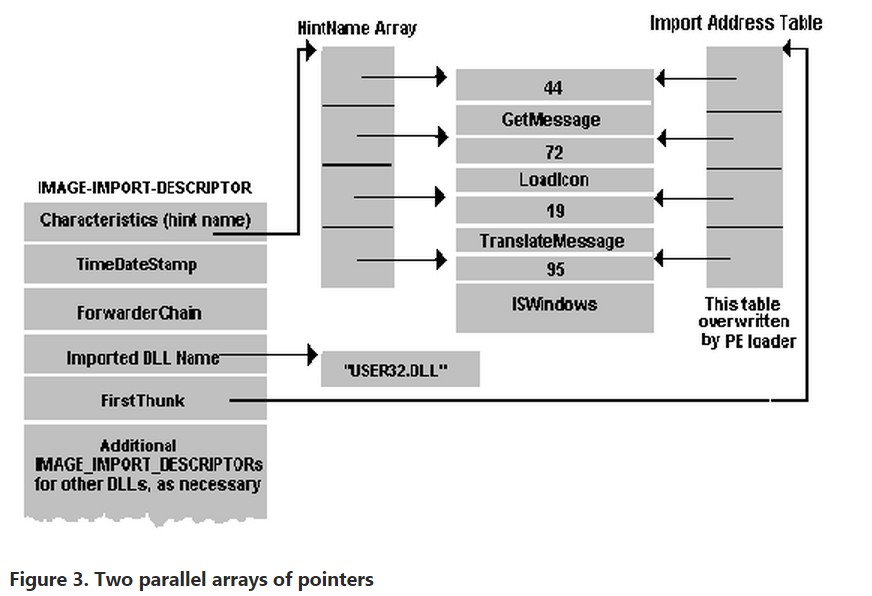
Table 9. Imports Table from an EXE File
GDI32.dll
  Hint/Name Table: 00013064
  TimeDateStamp:   2C51B75B
  ForwarderChain:  FFFFFFFF
  First thunk RVA: 00013214
  Ordn  Name
    48  CreatePen
    57  CreateSolidBrush
    62  DeleteObject
   160  GetDeviceCaps
    //  Rest of table omitted...

  KERNEL32.dll
  Hint/Name Table: 0001309C
  TimeDateStamp:   2C4865A0
  ForwarderChain:  00000014
  First thunk RVA: 0001324C
  Ordn  Name
    83  ExitProcess
   137  GetCommandLineA
   179  GetEnvironmentStrings
   202  GetModuleHandleA
    //  Rest of table omitted...

  SHELL32.dll
  Hint/Name Table: 00013138
  TimeDateStamp:   2C41A383
  ForwarderChain:  FFFFFFFF
  First thunk RVA: 000132E8
  Ordn  Name
    46  ShellAboutA

  USER32.dll
  Hint/Name Table: 00013140
  TimeDateStamp:   2C474EDF
  ForwarderChain:  FFFFFFFF
  First thunk RVA: 000132F0
  Ordn  Name
    10  BeginPaint
    35  CharUpperA
    39  CheckDlgButton
    40  CheckMenuItem

    //  Rest of table omitted...
There is one IMAGE_IMPORT_BY_NAME structure for each function that the PE file imports. An IMAGE_IMPORT_BY_NAME structure is very simple, and looks like this:
WORD    Hint;
BYTE    Name[?];
The first field is the best guess as to what the export ordinal for the imported function is. Unlike with NE files, this value doesn't have to be correct. Instead, the loader uses it as a suggested starting value for its binary search for the exported function. Next is an ASCIIZ string with the name of the imported function.
Why are there two parallel arrays of pointers to the IMAGE_IMPORT_BY_NAME structures? The first array (the one pointed at by the Characteristics field) is left alone, and never modified. It's sometimes called the hint-name table. The second array (pointed at by the FirstThunk field) is overwritten by the PE loader. The loader iterates through each pointer in the array and finds the address of the function that each IMAGE_IMPORT_BY_NAME structure refers to. The loader then overwrites the pointer to IMAGE_IMPORT_BY_NAME with the found function's address. The [XXXXXXXX] portion of the JMP DWORD PTR [XXXXXXXX] thunk refers to one of the entries in the FirstThunk array. Since the array of pointers that's overwritten by the loader eventually holds the addresses of all the imported functions, it's called the Import Address Table.
For you Borland users, there's a slight twist to the above description. A PE file produced by TLINK32 is missing one of the arrays. In such an executable, the Characteristics field in the IMAGE_IMPORT_DESCRIPTOR (aka the hint-name array) is 0. Therefore, only the array that's pointed at by the FirstThunk field (the Import Address Table) is guaranteed to exist in all PE files. The story would end here, except that I ran into an interesting problem when writing PEDUMP. In the never ending search for optimizations, Microsoft "optimized" the thunk array in the system DLLs for Windows NT (KERNEL32.DLL and so on). In this optimization, the pointers in the array don't point to an IMAGE_IMPORT_BY_NAME structure—rather, they already contain the address of the imported function. In other words, the loader doesn't need to look up function addresses and overwrite the thunk array with the imported function's addresses. This causes a problem for PE dumping programs that are expecting the array to contain pointers to IMAGE_IMPORT_BY_NAME structures. You might be thinking, "But Matt, why don't you just use the hint-name table array?" That would be an ideal solution, except that the hint-name table array doesn't exist in Borland files. The PEDUMP program handles all these situations, but the code is understandably messy.
Since the import address table is in a writeable section, it's relatively easy to intercept calls that an EXE or DLL makes to another DLL. Simply patch the appropriate import address table entry to point at the desired interception function. There's no need to modify any code in either the caller or callee images. What could be easier?
It's interesting to note that in Microsoft-produced PE files, the import table is not something wholly synthesized by the linker. All the pieces necessary to call a function in another DLL reside in an import library. When you link a DLL, the library manager (LIB32.EXE or LIB.EXE) scans the OBJ files being linked and creates an import library. This import library is completely different from the import libraries used by 16-bit NE file linkers. The import library that the 32-bit LIB produces has a .text section and several .idata$ sections. The .text section in the import library contains the JMP DWORD PTR [XXXXXXXX] thunk, which has a name stored for it in the OBJ's symbol table. The name of the symbol is identical to the name of the function being exported by the DLL (for example, _Dispatch_Message@4). One of the .idata$ sections in the import library contains the DWORD that the thunk dereferences through. Another of the .idata$ sections has a space for the hint ordinal followed by the imported function's name. These two fields make up an IMAGE_IMPORT_BY_NAME structure. When you later link a PE file that uses the import library, the import library's sections are added to the list of sections from your OBJs that the linker needs to process. Since the thunk in the import library has the same name as the function being imported, the linker assumes the thunk is really the imported function, and fixes up calls to the imported function to point at the thunk. The thunk in the import library is essentially "seen" as the imported function.
Besides providing the code portion of an imported function thunk, the import library provides the pieces of the PE file's .idata section (or import table). These pieces come from the various .idata$ sections that the library manager put into the import library. In short, the linker doesn't really know the differences between imported functions and functions that appear in a different OBJ file. The linker just follows its preset rules for building and combining sections, and everything falls into place naturally.
PE File Exports
The opposite of importing a function is exporting a function for use by EXEs or other DLLs. A PE file stores information about its exported functions in the .edata section. Generally, Microsoft linker-generated PE EXE files don't export anything, so they don't have an .edata section. Borland's TLINK32 always exports at least one symbol from an EXE. Most DLLs do export functions and have an .edata section. The primary components of an .edata section (aka the export table) are tables of function names, entry point addresses, and export ordinal values. In an NE file, the equivalents of an export table are the entry table, the resident names table, and the nonresident names table. These tables are stored as part of the NE header, rather than in distinct segments or resources.
At the start of an .edata section is an IMAGE_EXPORT_DIRECTORY structure (see Table 10). This structure is immediately followed by data pointed to by fields in the structure.
Table 10. IMAGE_EXPORT_DIRECTORY Format
DWORD Characteristics- This field appears to be unused and is always set to 0.
DWORD TimeDateStamp- The time/date stamp indicating when this file was created.
WORD MajorVersionWORD MinorVersion- These fields appear to be unused and are set to 0.
DWORD Name- The RVA of an ASCIIZ string with the name of this DLL.
DWORD Base- The starting ordinal number for exported functions. For example, if the file exports functions with ordinal values of 10, 11, and 12, this field contains 10. To obtain the exported ordinal for a function, you need to add this value to the appropriate element of the AddressOfNameOrdinals array.
DWORD NumberOfFunctions- The number of elements in the AddressOfFunctions array. This value is also the number of functions exported by this module. Theoretically, this value could be different than the NumberOfNames field (next), but actually they're always the same.
DWORD NumberOfNames- The number of elements in the AddressOfNames array. This value seems always to be identical to the NumberOfFunctions field, and so is the number of exported functions.
PDWORD *AddressOfFunctions- This field is an RVA and points to an array of function addresses. The function addresses are the entry points (RVAs) for each exported function in this module.
PDWORD *AddressOfNames- This field is an RVA and points to an array of string pointers. The strings are the names of the exported functions in this module.
PWORD *AddressOfNameOrdinals- This field is an RVA and points to an array of WORDs. The WORDs are the export ordinals of all the exported functions in this module. However, don't forget to add in the starting ordinal number specified in the Base field.
The layout of the export table is somewhat odd (see Figure 4 and Table 10). As I mentioned earlier, the requirements for exporting a function are a name, an address, and an export ordinal. You'd think that the designers of the PE format would have put all three of these items into a structure, and then have an array of these structures. Instead, each component of an exported entry is an element in an array. There are three of these arrays (AddressOfFunctions, AddressOfNames, AddressOfNameOrdinals), and they are all parallel to one another. To find all the information about the fourth function, you need to look up the fourth element in each array.

Table 11. Typical Exports Table from an EXE File
Name:            KERNEL32.dll
  Characteristics: 00000000
  TimeDateStamp:   2C4857D3
  Version:         0.00
  Ordinal base:    00000001
  # of functions:  0000021F
  # of Names:      0000021F

  Entry Pt  Ordn  Name
  00005090     1  AddAtomA
  00005100     2  AddAtomW
  00025540     3  AddConsoleAliasA
  00025500     4  AddConsoleAliasW
  00026AC0     5  AllocConsole
  00001000     6  BackupRead
  00001E90     7  BackupSeek
  00002100     8  BackupWrite
  0002520C     9  BaseAttachCompleteThunk
  00024C50    10  BasepDebugDump
  // Rest of table omitted...
Incidentally, if you dump out the exports from the Windows NT system DLLs (for example, KERNEL32.DLL and USER32.DLL), you'll note that in many cases there are two functions that only differ by one character at the end of the name, for instance CreateWindowExA and CreateWindowExW. This is how UNICODE support is implemented transparently. The functions that end with A are the ASCII (or ANSI) compatible functions, while those ending in W are the UNICODE version of the function. In your code, you don't explicitly specify which function to call. Instead, the appropriate function is selected in WINDOWS.H, via preprocessor #ifdefs. This excerpt from the Windows NT WINDOWS.H shows an example of how this works:
#ifdef UNICODE
#define DefWindowProc  DefWindowProcW
#else
#define DefWindowProc  DefWindowProcA
#endif // !UNICODE
PE File Resources
Finding resources in a PE file is quite a bit more complicated than in an NE file. The formats of the individual resources (for example, a menu) haven't changed significantly but you need to traverse a strange hierarchy to find them.
Navigating the resource directory hierarchy is like navigating a hard disk. There's a master directory (the root directory), which has subdirectories. The subdirectories have subdirectories of their own that may point to the raw resource data for things like dialog templates. In the PE format, both the root directory of the resource directory hierarchy and all of its subdirectories are structures of type IMAGE_RESOURCE_DIRECTORY (see Table 12).
Table 12. IMAGE_RESOURCE_DIRECTORY Format
DWORD Characteristics- Theoretically this field could hold flags for the resource, but appears to always be 0.
DWORD TimeDateStamp- The time/date stamp describing the creation time of the resource.
WORD MajorVersionWORD MinorVersion- Theoretically these fields would hold a version number for the resource. These field appear to always be set to 0.
WORD NumberOfNamedEntries
The number of array elements that use names and that follow this structure.
WORD NumberOfIdEntries- The number of array elements that use integer IDs, and which follow this structure.
IMAGE_RESOURCE_DIRECTORY_ENTRY DirectoryEntries[]- This field isn't really part of the IMAGE_RESOURCE_DIRECTORY structure. Rather, it's an array of IMAGE_RESOURCE_DIRECTORY_ENTRY structures that immediately follow the IMAGE_RESOURCE_DIRECTORY structure. The number of elements in the array is the sum of the NumberOfNamedEntries and NumberOfIdEntries fields. The directory entry elements that have name identifiers (rather than integer IDs) come first in the array.
A directory entry can either point at a subdirectory (that is, to another IMAGE_RESOURCE_DIRECTORY), or it can point to the raw data for a resource. Generally, there are at least three directory levels before you get to the actual raw resource data. The top-level directory (of which there's only one) is always found at the beginning of the resource section (.rsrc). The subdirectories of the top-level directory correspond to the various types of resources found in the file. For example, if a PE file includes dialogs, string tables, and menus, there will be three subdirectories: a dialog directory, a string table directory, and a menu directory. Each of these type subdirectories will in turn have ID subdirectories. There will be one ID subdirectory for each instance of a given resource type. In the above example, if there are three dialog boxes, the dialog directory will have three ID subdirectories. Each ID subdirectory will have either a string name (such as "MyDialog") or the integer ID used to identify the resource in the RC file. Figure 5 shows a resource directory hierarchy example in visual form. Table 13 shows the PEDUMP output for the resources in the Windows NT CLOCK.EXE.

Table 13. Resources Hierarchy for CLOCK.EXE
ResDir (0) Named:00 ID:06 TimeDate:2C3601DB Vers:0.00 Char:0
    ResDir (ICON) Named:00 ID:02 TimeDate:2C3601DB Vers:0.00 Char:0
        ResDir (1) Named:00 ID:01 TimeDate:2C3601DB Vers:0.00 Char:0
            ID: 00000409  Offset: 00000200
        ResDir (2) Named:00 ID:01 TimeDate:2C3601DB Vers:0.00 Char:0
            ID: 00000409  Offset: 00000210
    ResDir (MENU) Named:02 ID:00 TimeDate:2C3601DB Vers:0.00 Char:0
        ResDir (CLOCK) Named:00 ID:01 TimeDate:2C3601DB Vers:0.00 Char:0
            ID: 00000409  Offset: 00000220
        ResDir (GENERICMENU) Named:00 ID:01 TimeDate:2C3601DB Vers:0.00 Char:0
            ID: 00000409  Offset: 00000230
    ResDir (DIALOG) Named:01 ID:01 TimeDate:2C3601DB Vers:0.00 Char:0
        ResDir (ABOUTBOX) Named:00 ID:01 TimeDate:2C3601DB Vers:0.00 Char:0
            ID: 00000409  Offset: 00000240
        ResDir (64) Named:00 ID:01 TimeDate:2C3601DB Vers:0.00 Char:0
            ID: 00000409  Offset: 00000250
    ResDir (STRING) Named:00 ID:03 TimeDate:2C3601DB Vers:0.00 Char:0
        ResDir (1) Named:00 ID:01 TimeDate:2C3601DB Vers:0.00 Char:0
            ID: 00000409  Offset: 00000260
        ResDir (2) Named:00 ID:01 TimeDate:2C3601DB Vers:0.00 Char:0
            ID: 00000409  Offset: 00000270
        ResDir (3) Named:00 ID:01 TimeDate:2C3601DB Vers:0.00 Char:0
            ID: 00000409  Offset: 00000280
    ResDir (GROUP_ICON) Named:01 ID:00 TimeDate:2C3601DB Vers:0.00 Char:0
        ResDir (CCKK) Named:00 ID:01 TimeDate:2C3601DB Vers:0.00 Char:0
            ID: 00000409  Offset: 00000290
    ResDir (VERSION) Named:00 ID:01 TimeDate:2C3601DB Vers:0.00 Char:0
        ResDir (1) Named:00 ID:01 TimeDate:2C3601DB Vers:0.00 Char:0
            ID: 00000409  Offset: 000002A0
As mentioned earlier, each directory entry is a structure of type IMAGE_RESOURCE_DIRECTORY_ENTRY (boy, these names are getting long!). Each IMAGE_RESOURCE_DIRECTORY_ENTRY has the format shown in Table 13.
Table 14. IMAGE_RESOURCE_DIRECTORY_ENTRY Format
DWORD Name- This field contains either an integer ID or a pointer to a structure that contains a string name. If the high bit (0x80000000) is zero, this field is interpreted as an integer ID. If the high bit is nonzero, the lower 31 bits are an offset (relative to the start of the resources) to an IMAGE_RESOURCE_DIR_STRING_U structure. This structure contains a WORD character count, followed by a UNICODE string with the resource name. Yes, even PE files intended for non-UNICODE Win32 implementations use UNICODE here. To convert the UNICODE string to an ANSI string, use the WideCharToMultiByte function.
DWORD OffsetToData- This field is either an offset to another resource directory or a pointer to information about a specific resource instance. If the high bit (0x80000000) is set, this directory entry refers to a subdirectory. The lower 31 bits are an offset (relative to the start of the resources) to another IMAGE_RESOURCE_DIRECTORY. If the high bit isn't set, the lower 31 bits point to an IMAGE_RESOURCE_DATA_ENTRY structure. The IMAGE_RESOURCE_DATA_ENTRY structure contains the location of the resource's raw data, its size, and its code page.
To go further into the resource formats, I'd need to discuss the format of each resource type (dialogs, menus, and so on). Covering these topics could easily fill up an entire article on its own.
PE File Base Relocations
When the linker creates an EXE file, it makes an assumption about where the file will be mapped into memory. Based on this, the linker puts the real addresses of code and data items into the executable file. If for whatever reason the executable ends up being loaded somewhere else in the virtual address space, the addresses the linker plugged into the image are wrong. The information stored in the .reloc section allows the PE loader to fix these addresses in the loaded image so that they're correct again. On the other hand, if the loader was able to load the file at the base address assumed by the linker, the .reloc section data isn't needed and is ignored. The entries in the .reloc section are called base relocations since their use depends on the base address of the loaded image.
Unlike relocations in the NE file format, base relocations are extremely simple. They boil down to a list of locations in the image that need a value added to them. The format of the base relocation data is somewhat quirky. The base relocation entries are packaged in a series of variable length chunks. Each chunk describes the relocations for one 4KB page in the image. Let's look at an example to see how base relocations work. An executable file is linked assuming a base address of 0x10000. At offset 0x2134 within the image is a pointer containing the address of a string. The string starts at physical address 0x14002, so the pointer contains the value 0x14002. You then load the file, but the loader decides that it needs to map the image starting at physical address 0x60000. The difference between the linker-assumed base load address and the actual load address is called the delta. In this case, the delta is 0x50000. Since the entire image is 0x50000 bytes higher in memory, so is the string (now at address 0x64002). The pointer to the string is now incorrect. The executable file contains a base relocation for the memory location where the pointer to the string resides. To resolve a base relocation, the loader adds the delta value to the original value at the base relocation address. In this case, the loader would add 0x50000 to the original pointer value (0x14002), and store the result (0x64002) back into the pointer's memory. Since the string really is at 0x64002, everything is fine with the world.
Each chunk of base relocation data begins with an IMAGE_BASE_RELOCATION structure that looks like Table 14. Table 15 shows some base relocations as shown by PEDUMP. Note that the RVA values shown have already been displaced by the VirtualAddress in the IMAGE_BASE_RELOCATION field.
Figure 15. IMAGE_BASE_RELOCATION Format
DWORD VirtualAddress- This field contains the starting RVA for this chunk of relocations. The offset of each relocation that follows is added to this value to form the actual RVA where the relocation needs to be applied.
DWORD SizeOfBlock- The size of this structure plus all the WORD relocations that follow. To determine the number of relocations in this block, subtract the size of an IMAGE_BASE_RELOCATION (8 bytes) from the value of this field, and then divide by 2 (the size of a WORD). For example, if this field contains 44, there are 18 relocations that immediately follow:
 (44 - sizeof(IMAGE_BASE_RELOCATION)) / sizeof(WORD) = 18
WORD TypeOffset
This isn't just a single WORD, but rather an array of WORDs, the number of which is calculated by the above formula. The bottom 12 bits of each WORD are a relocation offset, and need to be added to the value of the Virtual Address field from this relocation block's header. The high 4 bits of each WORD are a relocation type. For PE files that run on Intel CPUs, you'll only see two types of relocations:
| 0 | IMAGE_REL_BASED_ABSOLUTE | This relocation is meaningless and is only used as a place holder to round relocation blocks up to a DWORD multiple size. |
| 3 | IMAGE_REL_BASED_HIGHLOW | This relocation means add both the high and low 16 bits of the delta to the DWORD specified by the calculated RVA. |
Table 16. The Base Relocations from an EXE File
Virtual Address: 00001000  size: 0000012C
  00001032 HIGHLOW
  0000106D HIGHLOW
  000010AF HIGHLOW
  000010C5 HIGHLOW
  // Rest of chunk omitted...
Virtual Address: 00002000  size: 0000009C
  000020A6 HIGHLOW
  00002110 HIGHLOW
  00002136 HIGHLOW
  00002156 HIGHLOW
  // Rest of chunk omitted...
Virtual Address: 00003000  size: 00000114
  0000300A HIGHLOW
  0000301E HIGHLOW
  0000303B HIGHLOW
  0000306A HIGHLOW
  // Rest of relocations omitted...
Differences Between PE and COFF OBJ Files
There are two portions of the PE file that are not used by the operating system. These are the COFF symbol table and the COFF debug information. Why would anyone need COFF debug information when the much more complete CodeView information is available? If you intend to use the Windows NT system debugger (NTSD) or the Windows NT kernel debugger (KD), COFF is the only game in town. For those of you who are interested, I've included a detailed description of these parts of the PE file in the online posting that accompanies this article (available on all MSJ bulletin boards).
At many points throughout the preceding discussion, I've noted that many structures and tables are the same in both a COFF OBJ file and the PE file created from it. Both COFF OBJ and PE files have an IMAGE_FILE_HEADER at or near their beginning. This header is followed by a section table that contains information about all the sections in the file. The two formats also share the same line number and symbol table formats, although the PE file can have additional non-COFF symbol tables as well. The amount of commonality between the OBJ and PE EXE formats is evidenced by the large amount of common code in PEDUMP (see COMMON.C on any MSJ bulletin board).
This similarity between the two file formats isn't happenstance. The goal of this design is to make the linker's job as easy as possible. Theoretically, creating an EXE file from a single OBJ should be just a matter of inserting a few tables and modifying a couple of file offsets within the image. With this in mind, you can think of a COFF file as an embryonic PE file. Only a few things are missing or different, so I'll list them here.
- COFF OBJ files don't have an MS-DOS stub preceding the IMAGE_FILE_HEADER, nor is there a "PE" signature preceding the IMAGE_FILE_HEADER.
- OBJ files don't have the IMAGE_OPTIONAL_HEADER. In a PE file, this structure immediately follows the IMAGE_FILE_HEADER. Interestingly, COFF LIB files do have an IMAGE_OPTIONAL_HEADER. Space constraints prevent me from talking about LIB files here.
- OBJ files don't have base relocations. Instead, they have regular symbol-based fixups. I haven't gone into the format of the COFF OBJ file relocations because they're fairly obscure. If you want to dig into this particular area, the PointerToRelocations and NumberOfRelocations fields in the section table entries point to the relocations for each section. The relocations are an array of IMAGE_RELOCATION structures, which is defined in WINNT.H. The PEDUMP program can show OBJ file relocations if you enable the proper switch.
- The CodeView information in an OBJ file is stored in two sections (.debug$S and .debug$T). When the linker processes the OBJ files, it doesn't put these sections in the PE file. Instead, it collects all these sections and builds a single symbol table stored at the end of the file. This symbol table isn't a formal section (that is, there's no entry for it in the PE's section table).
Using PEDUMP
PEDUMP is a command-line utility for dumping PE files and COFF OBJ format files. It uses the Win32 console capabilities to eliminate the need for extensive user interface work. The syntax for PEDUMP is as follows:
PEDUMP [switches] filename
The switches can be seen by running PEDUMP with no arguments. PEDUMP uses the switches shown in Table 17. By default, none of the switches are enabled. Running PEDUMP without any of the switches provides most of the useful information without creating a huge amount of output. PEDUMP sends its output to the standard output file, so its output can be redirected to a file with an > on the command line.
Table 17. PEDUMP Switches
| /A | Include everything in dump (essentially, enable all the switches) |
| /H | Include a hex dump of each section at the end of the dump |
| /L | Include line number information (both PE and COFF OBJ files) |
| /R | Show base relocations (PE files only) |
| /S | Show symbol table (both PE and COFF OBJ files) |
Summary
With the advent of Win32, Microsoft made sweeping changes in the OBJ and executable file formats to save time and build on work previously done for other operating systems. A primary goal of these file formats is to enhance portability across different platforms.
unit pelib;

interface

uses Windows;

const
  IMAGE_DOS_SIGNATURE    = $5A4D;       { MZ }
  IMAGE_OS2_SIGNATURE    = $454E;       { NE }
  IMAGE_OS2_SIGNATURE_LE = $454C;       { LE }
  IMAGE_VXD_SIGNATURE    = $454C;       { LE }
  IMAGE_NT_SIGNATURE     = $00004550;   { PE00 }

  IMAGE_SIZEOF_SHORT_NAME          = 8;
  IMAGE_SIZEOF_SECTION_HEADER      = 40;
  IMAGE_NUMBEROF_DIRECTORY_ENTRIES = 16;
  IMAGE_RESOURCE_NAME_IS_STRING    = $80000000;
  IMAGE_RESOURCE_DATA_IS_DIRECTORY = $80000000;
  IMAGE_OFFSET_STRIP_HIGH          = $7FFFFFFF;

type
  PIMAGE_DOS_HEADER = ^IMAGE_DOS_HEADER;
  IMAGE_DOS_HEADER = packed record      { DOS .EXE header }
    e_magic         : WORD;             { Magic number }
    e_cblp          : WORD;             { Bytes on last page of file }
    e_cp            : WORD;             { Pages in file }
    e_crlc          : WORD;             { Relocations }
    e_cparhdr       : WORD;             { Size of header in paragraphs }
    e_minalloc      : WORD;             { Minimum extra paragraphs needed }
    e_maxalloc      : WORD;             { Maximum extra paragraphs needed }
    e_ss            : WORD;             { Initial (relative) SS value }
    e_sp            : WORD;             { Initial SP value }
    e_csum          : WORD;             { Checksum }
    e_ip            : WORD;             { Initial IP value }
    e_cs            : WORD;             { Initial (relative) CS value }
    e_lfarlc        : WORD;             { File address of relocation table }
    e_ovno          : WORD;             { Overlay number }
    e_res           : packed array [0..3] of WORD; { Reserved words }
    e_oemid         : WORD;             { OEM identifier (for e_oeminfo) }
    e_oeminfo       : WORD;             { OEM information; e_oemid specific }
    e_res2          : packed array [0..9] of WORD; { Reserved words }
    e_lfanew        : Longint;          { File address of new exe header }
  end;

  PIMAGE_FILE_HEADER = ^IMAGE_FILE_HEADER;
  IMAGE_FILE_HEADER = packed record
    Machine              : WORD;
    NumberOfSections     : WORD;
    TimeDateStamp        : DWORD;
    PointerToSymbolTable : DWORD;
    NumberOfSymbols      : DWORD;
    SizeOfOptionalHeader : WORD;
    Characteristics      : WORD;
  end;

  PIMAGE_DATA_DIRECTORY = ^IMAGE_DATA_DIRECTORY;
  IMAGE_DATA_DIRECTORY = packed record
    VirtualAddress  : DWORD;
    Size            : DWORD;
  end;

  PIMAGE_OPTIONAL_HEADER = ^IMAGE_OPTIONAL_HEADER;
  IMAGE_OPTIONAL_HEADER = packed record
   { Standard fields. }
    Magic           : WORD;
    MajorLinkerVersion : Byte;
    MinorLinkerVersion : Byte;
    SizeOfCode      : DWORD;
    SizeOfInitializedData : DWORD;
    SizeOfUninitializedData : DWORD;
    AddressOfEntryPoint : DWORD;
    BaseOfCode      : DWORD;
    BaseOfData      : DWORD;
   { NT additional fields. }
    ImageBase       : DWORD;
    SectionAlignment : DWORD;
    FileAlignment   : DWORD;
    MajorOperatingSystemVersion : WORD;
    MinorOperatingSystemVersion : WORD;
    MajorImageVersion : WORD;
    MinorImageVersion : WORD;
    MajorSubsystemVersion : WORD;
    MinorSubsystemVersion : WORD;
    Reserved1       : DWORD;
    SizeOfImage     : DWORD;
    SizeOfHeaders   : DWORD;
    CheckSum        : DWORD;
    Subsystem       : WORD;
    DllCharacteristics : WORD;
    SizeOfStackReserve : DWORD;
    SizeOfStackCommit : DWORD;
    SizeOfHeapReserve : DWORD;
    SizeOfHeapCommit : DWORD;
    LoaderFlags     : DWORD;
    NumberOfRvaAndSizes : DWORD;
    DataDirectory   : packed array [0..IMAGE_NUMBEROF_DIRECTORY_ENTRIES-1] of IMAGE_DATA_DIRECTORY;
  end;

  PIMAGE_SECTION_HEADER = ^IMAGE_SECTION_HEADER;
  IMAGE_SECTION_HEADER = packed record
    Name            : packed array [0..IMAGE_SIZEOF_SHORT_NAME-1] of Char;
    PhysicalAddress : DWORD; // or VirtualSize (union);
    VirtualAddress  : DWORD;
    SizeOfRawData   : DWORD;
    PointerToRawData : DWORD;
    PointerToRelocations : DWORD;
    PointerToLinenumbers : DWORD;
    NumberOfRelocations : WORD;
    NumberOfLinenumbers : WORD;
    Characteristics : DWORD;
  end;

  PIMAGE_NT_HEADERS = ^IMAGE_NT_HEADERS;
  IMAGE_NT_HEADERS = packed record
    Signature       : DWORD;
    FileHeader      : IMAGE_FILE_HEADER;
    OptionalHeader  : IMAGE_OPTIONAL_HEADER;
  end;

{ Import Table }

 PIMAGE_IMAGE_IMPORT_DESCRIPTOR =^IMAGE_IMAGE_IMPORT_DESCRIPTOR;
 IMAGE_IMAGE_IMPORT_DESCRIPTOR  = packed record
    OriginalFirstThunk  : DWORD;
    TimeDateStamp       : DWORD;
    ForwarderChain      : DWORD;
    Name1               : DWORD;
    FirstThunk          : DWORD;
  end;

  PIMAGE_IMPORT_BY_NAME = ^IMAGE_IMPORT_BY_NAME;
  IMAGE_IMPORT_BY_NAME  = packed record
    Hint                : WORD;
    Name1               : array [1..150] of char;
  end;

//-----------------------------------------------------------------------------
// added by Sunshine

{Export Table}

  PIMAGE_EXPORT_DIRECTORY =^IMAGE_EXPORT_DIRECTORY;
  IMAGE_EXPORT_DIRECTORY = packed record
    Characteristics : DWORD;
    TimeDateStamp   : DWORD;
    MajorVersion    : WORD;
    MinorVersion    : WORD;
    Name            : DWORD;
    Base            : DWORD;
    NumberofFunctions : DWORD;
    NumberOfNames : DWORD;
    AddressOfFunctions : DWORD;
    AddressOfNames : DWORD;
    AddressOfNameOrdinals : DWORD;
  end;

//------------------------------------------------------------------------------


{ Resources }

  PIMAGE_RESOURCE_DIRECTORY = ^IMAGE_RESOURCE_DIRECTORY;
  IMAGE_RESOURCE_DIRECTORY = packed record
    Characteristics : DWORD;
    TimeDateStamp   : DWORD;
    MajorVersion    : WORD;
    MinorVersion    : WORD;
    NumberOfNamedEntries : WORD;
    NumberOfIdEntries : WORD;
  end;

  PIMAGE_RESOURCE_DIRECTORY_ENTRY = ^IMAGE_RESOURCE_DIRECTORY_ENTRY;
  IMAGE_RESOURCE_DIRECTORY_ENTRY = packed record
    Name: DWORD;        // Or ID: Word (Union)
    OffsetToData: DWORD;
  end;

  PIMAGE_RESOURCE_DATA_ENTRY = ^IMAGE_RESOURCE_DATA_ENTRY;
  IMAGE_RESOURCE_DATA_ENTRY = packed record
    OffsetToData    : DWORD;
    Size            : DWORD;
    CodePage        : DWORD;
    Reserved        : DWORD;
  end;

  PIMAGE_RESOURCE_DIR_STRING_U = ^IMAGE_RESOURCE_DIR_STRING_U;
  IMAGE_RESOURCE_DIR_STRING_U = packed record
    Length          : WORD;
    NameString      : array [0..0] of WCHAR;
  end;

  // debugging
  PDEBUG_EVENT = ^DEBUG_EVENT;
  DEBUG_EVENT = packed record
    dwDebugEventCode : DWORD;
    dwProcessid      : DWORD;
    dwThreadid       : DWORD;
  end;

{
    /* Predefined resource types */
    #define    RT_NEWRESOURCE      0x2000
    #define    RT_ERROR            0x7fff
    #define    RT_CURSOR           1
    #define    RT_BITMAP           2
    #define    RT_ICON             3
    #define    RT_MENU             4
    #define    RT_DIALOG           5
    #define    RT_STRING           6
    #define    RT_FONTDIR          7
    #define    RT_FONT             8
    #define    RT_ACCELERATORS     9
    #define    RT_RCDATA           10
    #define    RT_MESSAGETABLE     11
    #define    RT_GROUP_CURSOR     12
    #define    RT_GROUP_ICON       14
    #define    RT_VERSION          16
    #define    RT_NEWBITMAP        (RT_BITMAP|RT_NEWRESOURCE)
    #define    RT_NEWMENU          (RT_MENU|RT_NEWRESOURCE)
    #define    RT_NEWDIALOG        (RT_DIALOG|RT_NEWRESOURCE)

}

type
  TResourceType = (
    rtUnknown0,
    rtCursorEntry,
    rtBitmap,
    rtIconEntry,
    rtMenu,
    rtDialog,
    rtString,
    rtFontDir,
    rtFont,
    rtAccelerators,
    rtRCData,
    rtMessageTable,
    rtCursor,
    rtUnknown13,
    rtIcon,
    rtUnknown15,
    rtVersion);

{ Resource Type Constants }

const
  StringsPerBlock = 16;

{ Resource Related Structures from RESFMT.TXT in WIN32 SDK }

type

  PIconHeader = ^TIconHeader;
  TIconHeader = packed record
    wReserved: Word;         { Currently zero }
    wType: Word;             { 1 for icons }
    wCount: Word;            { Number of components }
  end;

  PIconResInfo = ^TIconResInfo;
  TIconResInfo = packed record
    bWidth: Byte;
    bHeight: Byte;
    bColorCount: Byte;
    bReserved: Byte;
    wPlanes: Word;
    wBitCount: Word;
    lBytesInRes: DWORD;
    wNameOrdinal: Word;      { Points to component }
  end;

  PCursorResInfo = ^TCursorResInfo;
  TCursorResInfo = packed record
    wWidth: Word;
    wHeight: Word;
    wPlanes: Word;
    wBitCount: Word;
    lBytesInRes: DWORD;
    wNameOrdinal: Word;      { Points to component }
  end;


implementation

end.

 浙公网安备 33010602011771号