JTAG TAP Controller
The TAP controller is a synchronous finite state machine that responds
to changes at the TMS and TCK signals of the TAP and controls the sequence of operations of the circuitry.
TAP controller state diagram
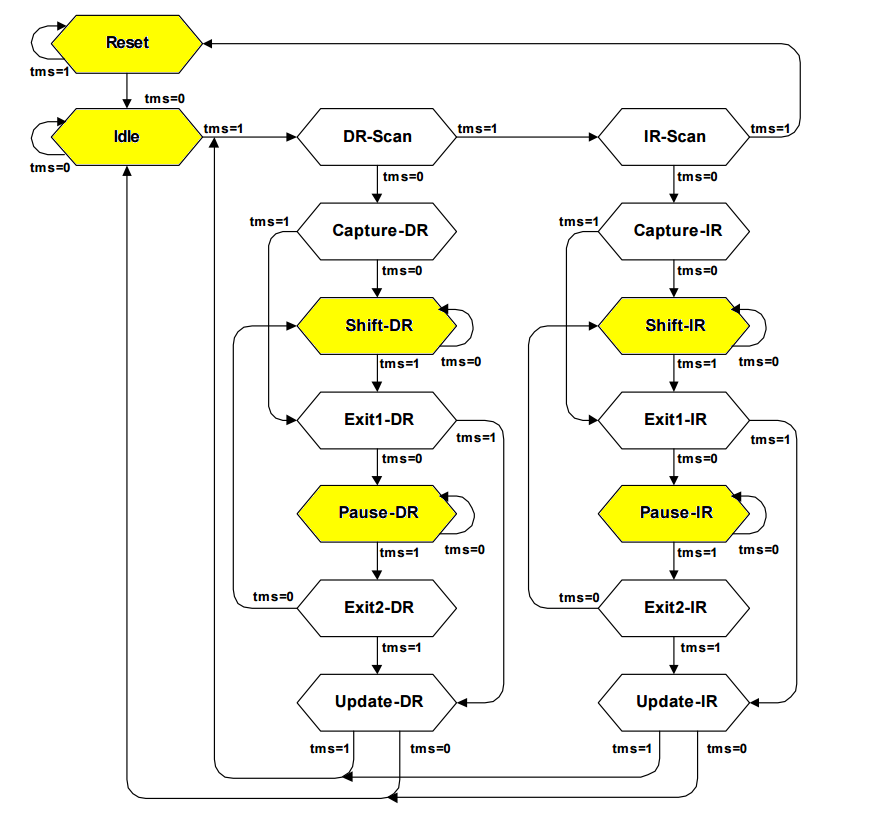
*黄*色*状态可以重复,其他状态只能出现一次,下个TCK上升沿会切换到下一个状态。
State descriptions
Reset
The test logic is disabled so that normal operation of the chip logic can continue unhindered.
No matter in which state the TAP controller currently is, it can change into Reset state if TMS is high for at least 5 clock cycles.
As long as TMS is high, the TAP controller remains in Reset state.
Idle
Idle is a TAP controller state between scan (DR or IR) operations.
Once entered, this state remains active as long as TMS is low.
DR-Scan
Temporary controller state. If TMS remains low, a scan sequence for the selected data registers is initiated.
IR-Scan
Temporary controller state. If TMS remains low, a scan sequence for the instruction register is initiated.
Capture-DR
Data may be loaded in parallel to the selected test data registers.
Shift-DR
The test data register connected between TDI and TDO shifts data one stage towards the serial output with each clock.
Exit1-DR
Temporary controller state.
Pause-DR
The shifting of the test data register between TDI and TDO is temporarily halted.
Exit2-DR
Temporary controller state.
Allows to either go back into Shift-DR state or go on to Update-DR.
Update-DR
Data contained in the currently selected data register is loaded into a latched parallel output (for registers that have such a latch).
The parallel latch prevents changes at the parallel output of these registers from occurring during the shifting process.
Capture-IR
Instructions may be loaded in parallel into the instruction register.
Shift-IR
The instruction register shifts the values in the instruction register towards TDO with each clock.
Exit1-IR
Temporary controller state.
Pause-IR
Wait state that temporarily halts the instruction shifting.
Exit2-IR
Temporary controller state. Allows to either go back into Shift-IR state or go on to Update-IR.
Update-IR
The values contained in the instruction register are loaded into a latched parallel output from the shift-register path.
Once latched, this new instruction becomes the current one.
The parallel latch prevents changes at the parallel output of the instruction register from occurring during the shifting process.

 浙公网安备 33010602011771号