SAE J1850 VPW Implement
---恢复内容开始---


OBDII Interface Project
When I can ever find enough time away from schoolwork, I try to work on an OBDII compliant portable ScanTool. However, with my current course load and lab projects progress on this project has been very slow. I first became interested in designing my own handheld ScanTool when my Dad purchased a PC-to-OBDII interface. The interface is simple, just a PIC16F84-20I/P programmed to send OBDII frames to the PC via RS-232. The interface works great, however, it is somewhat impractical because in order to use it you must drag a laptop all the way out to the car. That got pretty tedious; especially when you get everything out to the car and realize the laptop battery is dead! Thus the idea of my own self-contained ScanTool was born. The idea is to have the OBDII interface, DTC lookup tables, and an information read-out all on one tool.
***UPDATE 3/23/2008***
It has been quite a while since I've made an update to this page. Mainly because of the fact that I haven't worked on this project in several years. Then today as I was browsing through old code for the T6963C Graphic LCD I came across a goofy mistake on my part. When I packaged and uploaded the library files, I zipped the wrong ones. The ones that got uploaded contained an error. I have uploaded the correct copy of the library so the T6963C drivers should be corrected.
The receive routine has now been completed and is no longer theory only. Click the "Receive Routine" link above to be taken to the appropriate section. Also, for some reason I forgot to include the CRC calculation routine in the previous upload. This has since been added to the library. It will not be discussed thoroughly (just information on how to use it) and credit must be given to the original author, B. Roadman www.obddiagnostics.com.
Be sure to check out the forum for the latest updates and design notes. The link is provided to the left. The forum contains the latest announcements, fixes, and is a place to post your comments and questions.
The “Brain”
The core of this project is a Microchip PIC16F877(A) microprocessor. The PIC interfaces with the OBD bus, retrieves any returned DTC information from the external EEPROM chips, and displays the information on a 64X128 Graphic LCD. Currently, the firmware will only have support for the J1850 VPW protocol. However, in future versions I do intend to extend the supported protocols to include the J1850 PWM and ISO-9141 but expansion will be dependant upon the receipt of protocol specifications.
Before I delve into the nitty-gritty of how the PIC handles each of the tasks above, a word should be said about the J1850 VPW protocol. J1850 VPW is an “asynchronous, master-less, peer-to-peer protocol that supports equal network access for every node (1).” The J1850 bus supports CSMA/CR (Carrier Sense, Multiple Access, Collision Resolution) arbitration for ultimate bus control. Interpretation? Basically any number of nodes can begin transmitting at any given time, each fighting for control of the bus while doing so, and each node has equal priority on the network. If each node has equal priority, how is the “winner” of the bus determined you ask? Well, bus control is determined through a process called arbitration. Due to the hardware architecture this process allows “active” symbols to win over “passive” symbols. Therefore, the node that has the most “active” symbols in the beginning of their message frame will ultimately control the bus. More on “active” versus “passive” symbols to follow in a moment. There are two key features that make this type of network possible:
- The bus is weakly pulled to ground.
- Asynchronous communication – each transmitting node sees its own message “echoed” back as it is transmitting.
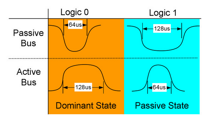
The first feature is important in that when idle, the bus will settle to the ground state. This is important for the Carrier Sense (CS) portion of the protocol. Before beginning transmission, each node must first “listen” or poll the bus for a certain amount of time to determine if the bus is available, i.e. in the ground state. The second feature is important for arbitration purposes. If a node is transmitting a “passive” symbol but “sees” an active symbol echoed back then that node has lost arbitration and should cease transmitting and continue functioning as a receiver. This process continues for each remaining node until only one node is left. The dominance of active symbols over passive symbols ensures message integrity. So what is an active or passive symbol? Well, in the J1850 VPW protocol a “1” is not necessarily defined as a high potential and a “0” is not necessarily defined as a low potential like you might expect. Instead, each character is represented by the amount of time the bus stays in a particular state. This leads to two possible representations for each bit, one active and one passive. In particular, a “0” bit is represented by either a high potential (active) lasting for 128mS or a low potential (passive) lasting for 64mS. Likewise a “1” bit is represented by either a high potential (active) lasting for 64mS or a low potential (passive) lasting for 128mS. The bus may transition between high and low but it is the amount of time the bus spends in each state that determines the character. This is particularly useful in “noisy” environments, such as your automobile. These timings are shown below in figure 5.
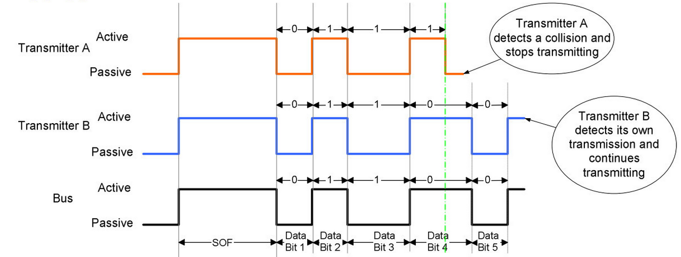
This type of encoding scheme leads to the dominance of a “0” over a “1”. An example of the arbitration process is shown below in figure 2 demonstrating the dominance of an active symbol over a passive one. (I didn’t assign the figure numbers; both came from different parts of the same text.)
In the above timing diagram three nodes (A, B, & C) all begin talking at the same time. The bottom trace shows what potential is actually being represented on the bus. In this example, all three messages start out the same, a SOF (Start of Frame) symbol (discussed in a moment), and the following data bits- 00110. At this point node C wishes to continue transmission with a 1 bit but both nodes A & B wish to continue with a 0 bit. Therefore, node C attempts to let the bus settle back to the low potential state but nodes A & B keep driving the bus to a high potential. Node C detects this contention and drops out of the transmission. Nodes A & B continue transmitting for two more bits until node A wants to transmit a 1 but node B wants to transmit a 0. Node A detects this contention and drops out of the transmission. Node B continues to transmit until its last bit has been sent. Looking at the bottom trace, the J1850 Bus reflects that the message sent by node B has been left intact. Following the completion of node B’s transmission, nodes A & C can begin re-transmitting their messages, again arbitrating for control of the bus.
So what’s that SOF thingy at the beginning of each message? Recall that the idle state for the bus is a low potential. The SOF or Start of Frame symbol is a character used to denote the beginning of a message frame. Basically it’s a node’s way of waving its hand and saying, “Hey, I wanna talk now.” It is defined as a high potential on the bus lasting for a nominal period of 200mS.
Now you might be asking, “Why did I go into such a lengthy discussion about the protocol here when this section is supposed to be about the PIC?” and the answer is it will help you understand the logic in the code that I have written. So now the moment you’ve been waiting for, a functional description of the code. (Drum roll anyone?)
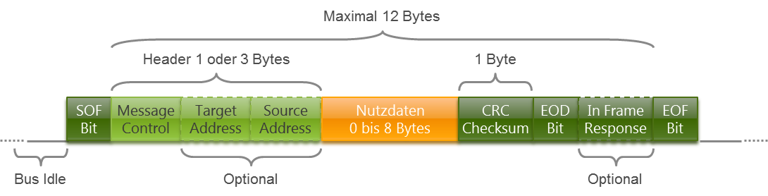
Basically, there is nothing too special about the program itself. In order to ensure accurate symbol timings, the Capture/Compare/PWM module on the PIC is used to toggle an output pin to drive the bus. In order to do this we must first configure both the Timer1 module and the CCPXCON to work together to create our bit symbols. First we need to determine exactly how long a message frame will be in seconds and configure timer1 to be able to count this long without overflowing. If timer1 overflows then the amount of work we have to do as programmers has just increased greatly. A complete J1850 message frame looks like this: SOF + 1 or 3 header bytes + 10 or 8 data bytes + 1 CRC byte + EOF. The J1850 defines the maximum number of bytes that can be transmitted in a single frame is 12 and that includes the CRC byte. Therefore, from a standpoint of timing the longest message actually looks like this: SOF + 12 data bytes + EOF. Since SOF and EOF have predefined timings the only variable we have in terms of time is the 12 data bytes.
Looking at the defined timings for each bit we determine that the “longest” byte that can be sent in terms of time would be0b_1010_1010 or 0xAA. The time division per symbol in this case would be 128mS. So for an 8-bit byte the total time for this byte would be 8 * 128mS = 1024mS or 1.024mS. If we have a message composed of 12 of these bytes (remember this is a worst case scenario, it can never actually be used as a valid message frame) the total time for this message would be 12 * 1.024mS = 12.288mS. Adding to this the time allotted for the SOF and EOF symbols we arrive at a total frame time of 12.288mS + 500mS = 12.788mS. So as long as timer1 does not overflow within 12.788mS we will be fine. Using a 20MHz crystal for the PIC translates to a 200nS instruction cycle. Since timer1 is a 16-bit wide timer, at this frequency, technically we could get away without using a prescaler for timer1. (2^16 * 200nS = 0.0131072 S or 13.1072mS > 12.788mS) However, in order to compensate for clock mismatch on the network (remember the protocol is asynchronous meaning there is no “master” clock so just because our clock says that time’s up doesn’t mean that all the other node’s clocks say it is) and just to make the calculations simpler in the program I opted to use a prescaler value of 1:4. This gives us an overflow time of 2^16 * 200nS * 4 = 0.0524288 S or 52.4288mS. This not only has ample room for clock mismatch but also gives us a break in that both our 128mS and 64mS bit times can be loaded by a single 8-bit byte value. We now know how we need to set up the timer1 module so lets go ahead and do that.
f877_t1con = 0x00 -- 1:4 prescaler for timer1
t1ckps1 = on
tmr1if = false -- clear interrupt flag
f877_tmr1h = 0x00
f877_tmr1l = 0x00


f877_t1con = 0x00 -- 1:4 prescaler for timer1
t1ckps1 = on
tmr1if = false -- clear interrupt flag
f877_tmr1h = 0x00
f877_tmr1l = 0x00


f877_t1con = 0x00 -- 1:4 prescaler for timer1
t1ckps1 = on
tmr1if = false -- clear interrupt flag
f877_tmr1h = 0x00
f877_tmr1l = 0x00
So now we have timer1 setup and initialized with our 1:4 prescaler and the timer’s high and low registers have been cleared. It’s time to move on to the compare registers.
I’m assuming that if you are reading this site then you already have at least a basic understanding of PIC’s and of the integrated modules. If you already know about the compare module and its features then you can skip down to the microchip. For those who are not familiar with PIC’s or do not really understand what the compare module does then read on. To start, the PIC16F877 has all sorts of handy little “features” built into the hardware inside the chip. For example, the F877 has a built-in 10-bit wide A/D converter, built in USART and MSSP for serial communications, built-in Capture/Compare/PWM modules, and many many more features. These built in hardware features make our lives as programmers much simpler since all of the “hard stuff” associated with coding these into our programs has been taken care of by the chip. They also reduce the need for many external chips that would be required if these features were not integrated. We will be primarily focusing on the Capture/Compare/PWM module with this project. The CCP module is a set of two registers 8-bits wide + 1 control register that can be setup to “raise a flag” when either a value from timer1 has been captured, or when timer1 has reached a certain value. It can be used to control the time base for a Pulse Width Modulated output. The PIC16F877 has two CCP modules onboard referred to as CCP1 and CCP2 (how original huh?). From the datasheet:
Each Capture/Compare/PWM (CCP) module contains a 16-bit register which can operate as a:
• 16-bit Capture register
• 16-bit Compare register
• PWM Master/Slave Duty Cycle register
So what does the CCP capture or compare? Well timer1 of course! The control register is where the CCP module is configured to perform its required task. When it is configured as a 16-bit Compare register a user-determined value is loaded into the 2 x 8-bit CCP registers. Timer1 is then allowed to run freely, from either an internal or external clock. When the value in timer1 matches the loaded value in the CCP registers one of four things can happen:
- Compare mode, set output on match (CCPxIF bit is set)
- Compare mode, clear output on match (CCPxIF bit is set)
- Compare mode, generate software interrupt on match (CCPxIF bit is set, CCPx pin is unaffected)
- Compare mode, trigger special event (CCPxIF bit is set, CCPx pin is unaffected); CCP1 resets TMR1; CCP2 resets TMR1 and starts an A/D conversion (if A/D module is enabled)
What’s all this mumbo-jumbo you ask? Remember earlier when I said that I use the compare module to toggle an output pin to generate my bit symbols that is what situations 1 & 2 describe above. The CCP module can be configured to control an output pin on the PIC. In situation 1, when a match between timer1 and the CCP module occurs, the CCP module immediately sets or drives the output pin high. Situation 2 describes the opposite, when a match occurs the CCP module drives the output pin low. What might not be so implicit in this is that when the CCP module is configured to drive the output pin low it first places the output pin in a high potential state while it waits! It wouldn’t make any sense to drive a pin low that was already low now would it? Both situations 1 & 2 above do not affect the value that is loaded in the timer. Situation 3 is useful in that it does not affect the state of the output pin; it only raises its hand and says, “Hey look, timer1 has matched me!” Situation 4 is similar to situation 3 in that it doesn’t affect the state of the output pin, but it does do some other things. Both CCP1 and CCP2 will reset timer1, i.e. start it over at 0, but CCP2 also does something a little extra; it starts an A/D conversion if the chip is so configured. All 4 situations raise the same flag I mentioned in situation 3.
When the CCPX module is configured to capture, the CCPX module will “take a picture” of the current value stored in timer1. When this happens depends upon how the CCPX module is configured. In capture mode, the CCPX module can be configured in one of 4 ways:
- Capture mode, every falling edge
- Capture mode, every rising edge
- Capture mode, every 4th rising edge
- Capture mode, every 16th rising edge
Now you say, “every rising/falling edge of what?” Well, the CCPX module watches an input pin very closely. When it is configured to capture on the rising edge of this input, the module will capture the timer1 value when the input pin makes a transition from low to high. When it is configured to capture on the falling edge it does so when the input pin transitions from high to low. See… rising edge – low to high, falling edge – high to low. This stuff is easy. The last two modes don’t really warrant an explanation since you already understand what rising and falling edges mean J.
The PWM portion of the module is not used in this project so it will not be discussed. (I’m already long-winded enough don’t you think?) If you want to know more about PWM then grab yourself a copy of the datasheet and start reading.
In this project we will be using the CCP2 register for data transmission and CCP1 & either timer2 or CCP2 for data reception. Since I haven’t really finished coding the data reception part I haven’t decided on which combination will be used. Data reception will be discussed from a software theory point of view only later in this document. Right now though we will focus on data transmission. The reason I decided to use the timer1/CCP2 combo for data transmission is because of the CCP’s ability to directly manipulate an output pin. This will provide us with very consistent and precise bit symbol timings with little software overhead. Recall we already have timer1 configured for our appropriate 1:4 prescaler and its registers have been reset to 0x00. That leaves us with configuring the CCP2 register. So how do we do that? First we need to determine what we want the CCP2 module to do. Looking at the J1850 specs, all data is transferred using and alternating active/passive scheme. Look back up at figure 2 to refresh you memory if you need to. This means that there is only one transition between bits. Sounds like a perfect job for the CCP2 module doesn’t it? I mean, use the CCP2 module to toggle our output pin at predefined intervals, you’d think that is what it was designed to do J . And you thought this was going to be hard. What makes this not so simple, however, is that each bit has different time intervals associated with each state. Therefore we need to update the compare registers dynamically, or “on-the-fly” while we are transmitting. Now I could be mean and simply post the entire 225 line send procedure and say have fun, but I will walk through each portion of the routine so that everyone can understand what exactly is going on. The entire library is available for download at the end of this document but why would you skip ahead and miss out on all the explanations?
We are faced with a problem; we need to somehow dynamically control the period between our output pin changes. We have been given somewhat of a break though. It seams that the mechanical engineers over at the SAE group got smart and hired an electrical engineer to work out this little multiplexing problem. The EE simply said, “if you’ve got to have two different time periods for each symbol, at least make the periods consistent.” As such our break is that we only have two time periods we need to worry about, 64mS and 128mS. The SOF and EOF symbols are a different matter but we’ll worry about those in a minute.
So how do we use this “gift” to our advantage? Well, we know that timer1 will be running at a fixed frequency. (For our purposes its frequency is fixed anyway, frequency drift and phase changes don’t exist for us J) We also know that we only have two nominal time periods we have to worry about, 64mS and 128mS. So we should be able to calculate exactly how many timer1 “ticks” occur between each of these time periods right? This is a fairly straightforward calculation. For the 64mS period we have: 64mS/(200nS*4) = 80D or0x50. Or if you prefer to use frequency instead of instruction cycle times: (5MHz/4) * 64mS = 80D or 0x50. By common sense, the number of ticks for 128mS should be exactly double that of 64mS but we’ll work through the calculations anyway just to be sure.128mS/(200nS * 4) = 160D or 0xA0. No surprise there. Lets go ahead and define those as constants to be used later. Place these definitions at the beginning of your program. The per_sof and per_eof constants deal with the SOF and EOF symbol periods respectively. We’ll talk about those later. The constants comp_drive_low, comp_drive_high, and comp_only are the required values that need to be loaded into the CCP2 control register to get it to do what we want it to do.
|
Ok so now we know how many timer ticks are between each respective interval, but how do we use that info? I should probably just show you first and then try to explain it. Here is the beginning part of the vpw_send procedure:
|
And this is the condensed version. J Breaking the above code snippet down into sections let’s start with the beginning.
|
Now I am going to assume that you are familiar with the JAL language so I am going to skip the syntax speech and get right to telling you what the variables are. The two parameters that are passed to this function are data and send_sof. Data holds the byte that is to be transmitted and send_sof is a flag that tells the function that the data byte needs to be preceded by a SOF symbol. The first defined variable is the bit variable error_flag. This is pretty self-explanatory; if this flag is ever set then an error has occurred; such as loosing arbitration. The second variable that is declared is the bit variable bit_out. It has been defined to be the MSB of the byte parameter data. This bit variable holds the current bit that is to be transmitted. Since this bit cannot be trusted to hold the last known value, it gets a volatile modifier. The next variable that is declared is the variable dom_pass. This is a flag that tells the function if the current symbol should be active or passive. A “1” = active, “0” = passive. Since the first bit of every byte being transmitted is always a passive symbol, this bit initializes to the passive state. The next three bytes that are defined deal with the arbitration issue and will be discussed later. The last variable that is defined is the variable next_bit. This is a byte variable that holds the number of timer ticks the output pin should remain in its current state. It should also be mentioned that this function returns a bit value. If the transmission was successful then the function returns true. If the transmission failed for whatever reason, then the function returns false.
Ok that was easy enough, on to the next part.
|
The first line sets up a loop that will repeat a total of 8 times. Makes sense since we are transmitting 8-bits each time. The next construct determines what the bit to be sent is, a 1 or a 0, and whether it is an active symbol or a passive symbol. I’ll leave the logic decryption to you. Once the type and state of the current bit symbol have been determined, then the next_bit register is loaded with the appropriate period length. So far so good, what’s next?
|
This is where things get a little more conceptual. I need to back up some and divulge some more of the theory behind this procedure before the next bit of code can be explained exactly. This procedure is limited by the fact that it can only send one byte of data at a time. Since JAL does not have support for passing “arrays” as parameters to procedures and I am too lazy to set it up to pass both the starting address pointer and array width parameters, I worked around this one-byte limitation. Since J1850 messages alwayscontain more than one byte of information, there needs to be a method for calling this procedure repeatedly without disturbing the timing between bytes. If you think about it, if the timer were stopped every time at the end of the procedure there would be no way to account for the lost time between the procedure return, procedure recall, re-initialization of the parameters, and finally updating the output pin accordingly. For a particular message frame, the result would be bit symbols that would have worse and worse pulse periods between bytes each time this procedure was called. So how do we work around this one byte limitation without causing a time skew between bytes? The answer is to have 1 timer that runs constantly for the duration of the message frame. This way we have a common time base for each byte that is being transmitted. Ok so what does this mean? Well, when this procedure is called for the first time, it starts timer1 counting, once all 8-bits of the current data byte have been transmitted, the procedure returns, leaving timer1 running in the process. The procedure is then called again and the next byte is then transmitted out using the previous “match point” from the last byte transmitted as a reference. The result is a complete message frame that is devoid of time skew.
“Wait, I’m still confused! Where is timer1 started? How does this relate to using the number of timer ‘ticks’ between transitions? What did you mean by ‘match point’?” These are all very good questions that need to be answered before moving on. First of all timer1 is started in the portion of code that has been snipped. Don’t worry, I’ll tell you the general idea’s behind what is going on in there in a moment, but first, we need to talk more about the timer “ticks.” Lets take a step back for a moment and ask ourselves a simple physics problem, “If I start out at point A and it takes X seconds to go to point B if I am traveling at Y m/s, how long do I need to travel to get to point B if I travel at Y m/s?” This is a simple enough problem, you just need to travel for X seconds, that is assuming your direction is constant and is towards point B and Y is much less than the speed of light J. The same principle applies to our number of timer ticks, only in our case our “velocity”, Y, is our clock rate, our position is one of “ticks”, point B is the number of “ticks” later that we expect a transition to occur, and point A is our last known “match point.” So what is a “match point?” It is a term that I am using to define a point in “ticks” when our timer1 module “matches” or compares with the value we have stored in the CCP2 module. Still a little fuzzy? I’ll explain further. For this case lets say that we take point A to be defined at the point timer1 = 0, i.e. point A’s “position” is at 0 ticks. Now lets say that we want to travel away from point A for 64mS to point B and then take a rest break. How far away from point A is point B in terms of ticks if our “velocity” is 1,250,000 ticks/s? Well we’ve actually already done this calculation remember? We determined that for our given “velocity” or clock rate, 64mS is only 0x50 ticks away. That means for our given clock rate, if we start out at point A and count off 0x50 ticks then we will be at point B, i.e. point B’s position is at timer1 = 0x50. Now lets say that we want to leave point B and travel for another 64mS to point C. How far away are we now from point A? Well since this is only one-dimensional motion and 64mS equates to 0x50 ticks, we are now 0x50 ticks away from point B. Point B is 0x50 ticks away from point A so we are now 0x50 + 0x50 = 0xA0 ticks away from point A. This is the principle behind the timer registers. Each tick translates to a specific amount of time. So if we wanted to time 128mS we would simply count off 0xA0 ticks. If you are already familiar with timers and how to use them I am sorry for the over-simplified breakdown. If you aren’t as familiar, then I hope you learned something.
The point of that whole analogy was to prove that ticks correspond to time and that the same number of ticks will always represent the same amount of time provided that the clock and prescaler values remain constant. So if we want to measure 64mS from any arbitrary point P all we need to do is add the appropriate number of ticks to the point and wait. This is the principle that I applied above. From the comments in my code:
-- start of frame takes care of period adjustment for first bit. If current
-- iteration is not sending a SOF, must adjust new period by adding pulse width
-- to current ccp2H:ccp2L registers.
If you follow the code example above, when send_sof is false, i.e. current iteration is not sending a SOF symbol, the next transition time for the CCP2 output pin is simply the previous transition time + appropriate number of ticks for current symbol. Ok everybody on the same page now?
What about when send_sof is true? In the portion of code that is missing, basically three main things occur.
1. The bus is “listened” to in order to determine if it is idle.
2. Once the bus is idle, a SOF character is generated and timer1 is started.
3. The period register is loaded with the appropriate value for the first bit to be transmitted.
The actual code and in-depth descriptions for each of these will be given later. Until then, “On to the next part!”
|
This is a not-so-idle idle loop to stall the PIC while it is waiting for the CCP2 module to raise its hand and wave. Inside this loop is where the first part of the all-important arbitration takes place and will be described in full detail a little later. That was pretty painless so what about the last little bit?
It’s actually pretty painless as well, even the part that has been snipped, for it simply toggles the dominate/passive indicator bit and reconfigures the CCP2 module to drive the pin to the next state in the event of a timer1 match. The portion that has been cut is the second half of arbitration detection and will be covered later. The CCP2 module’s “waving hand” is then cleared to prepare for the next compare and the next bit to be transmitted is then shifted into place. The for 8 loop end is then reached so it starts back again at the top. If the for 8 loop finishes without error, then the function returns a true value indicating that the process has completed successfully.
|
Pheww, that was a lot of work for something so simple. Well now its time to get to the stuff that I left out. (evil grin spreads across my face J) No, it’s not really that hard, or complicated, its just…well you’ll see.
Let me begin by first reminding you that before beginning any transmission the first thing the PIC must do is make sure that the bus is idle. The J1850 specs require a nominal period of 300mS of separation between message frames. This means that there must be 300mS between the last falling edge of the last message and the first rising edge of the next message’s SOF. So how do we determine if the bus is idle, and once it is idle how do we know how long it’s been idle? First we begin by setting up our timer module to count out 300mS so lets go ahead and perform that calculation. 300mS / (200nS * 4) = 375D or 0x177. Uh oh, this value is greater than 255 or 0xFF, the largest number that can be represented by 8-bits. So what do we do? Well actually, since timer1 is a 16-bit wide timer we don’t have to do anything. But rather than have to worry about performing 16-bit reads and writes on an active counter, I opted to change the prescaler value for the idle checking routine. I know that there are very good arguments against doing this but I like simplicity. Plus on the PIC’s I’ve tested, we get an added bonus doing it this way. Whether or not this bonus will be applicable to you depends on your particular PIC and oscillator. So keep in mind that you might have to fiddle with the timings to get the correct results. I will explain the bonus in a moment. In the meantime, lets continue with setting up timer1 for EOF/IFS detection. If we read the J1850 specs carefully, we will notice that the 300mS time period is a nominal value. In reality the IFS (inter-frame separation) is satisfied when at least 280mS has passed. Quoted directly from the J1850 specs for VPW IFS timings:
Inter-Frame Separation (IFS) - Inter-Frame Separation is used to allow proper synchronization of various nodes during back-to-back frame operation.
A transmitter that desires bus access must wait for either of two conditions before transmitting a SOF (see Figure 19):
a. IFS minimum has expired (Tv6).
b. EOF minimum and another rising edge has been detected (Tv4).
J1850 defines Tv6 to be no less than 280mS. So this is the value that we actually set our timer to measure. This is where our bonus comes into the picture. When the timer times out at 280mS, there is a latency period due to the time it takes to reconfigure and reset the timer and return from the procedure call. And by some stroke of luck, the amount of time this takes places the first bus transition right at 300mS. So we detect the minimum amount of time between frames passing, and our SOF symbol begins right around the nominal 300mS mark. We got lucky and everything fell into spec on that one. Also, only checking for the minimum IFS time simplifies the idle-checking routine greatly as you will see. So how do we load the CCP2 module to match at 280mS? Well we still need to reconfigure timer1 for a larger prescaler since we really want to stay away from working with 16-bit numbers if at all possible. The only available option we have left is a 1:8 prescaler. By selecting this new prescaler we determine the value to load into the CCP2 compare register to be 280mS / (200nS * 8) = 175D or 0xAF. So now that we now know how many ‘ticks’ we have to wait for the IFS minimum to pass, how to we tell if the bus is idle? Basically we just poll the bus and time how long it stays in the low potential. Here let me show you. The following code is the idle checking routine with explanations to follow.
|
The first 7 lines are simply initializing the routine. They make sure that the timer is not already running, reset the prescaler value for timer1 to 1:8, and reset the timer. They also clear the interrupt flag for the CCP module just in case it somehow was left set. The next three lines set up the CCP2 module to compare only. NO output pin is affected when a match occurs in this routine. The first while loop initially polls the bus to determine if it is active already. If the bus is active then the PIC just sits and does nothing until the bus goes low again. If the bus is already low, or we have waited for it to become low, then the next line is executed and the timer is started. Then in the same manner as before, we simply wait until the appropriate number of ticks has passed. While we are waiting, we are constantly polling the bus to see if it becomes active. If it does, then we know that a node must still be transmitting and our timer starts over. This is repeated until the existing message has finished and the minimum separation time has passed. And since we are only waiting for the minimum separation time between messages, any active symbol detected must be, by default, part of an existing message frame. That is how we get around dealing with condition “B” directly. As long as we are still in that loop then the EOF minimum time has not passed, therefore we don’t need to distinguish SOF’s from regular bits here. The last few lines stop and reset the timer. We now have a method for determining exactly when the bus becomes available for transmission.
So what’s next?
After the bus becomes available, we need to generate our SOF symbol. This is one of the sections of code I removed from the vpw_send function presented above and it will now be presented.
|
This is the complete “if send_sof then” statement. It shows how the SOF symbol is generated. Recall that the bit send_sof is one of the parameters that are passed to the function. This is how the function distinguishes the first data byte from the rest. Once we have determined that this is the first byte of the message frame, we need to begin the process for transmitting. You’ll notice that the very first thing that the function now does is wait for the bus to become available. The technical stuff has already been presented for the idle checking procedure so I won’t elaborate any further. Once the bus becomes available then a SOF symbol is generated in the exact same manner I described before for the rest of the data bits. What might not be apparent here is where the bus is placed in the high potential state marking the beginning of the SOF. Remember, in order for the CCPX module to drive the output pin low, it must first be in the high state. When the CCP2 module is configured to drive the bus low, it auto-magically drives the output pin high for us. Next, the CCP2 module is loaded with the number of ticks it must count out for the SOF period. The while loop simply places the PIC in a holding pattern until the SOF is finished. Since our SOF will be present for the exact J1850 spec, arbitration here is not needed. If another node is generating a SOF at the same time and its period happens to be a little shorter that’s ok, our PIC will continue transmitting and the other node will simply chalk it up to clock mismatch, as our PIC does if it is the “shorter” SOF. That’s where the while vpwin loop comes in. If our SOF symbol has completed but the bus is still active then that means there are only three options to describe the situation.
1) Clock mismatch – another node generating its SOF has yet to complete
2) A “Break” symbol is being transmitted
3) A bus fault has occurred, i.e. the bus has been shorted to the “+” terminal
What the PIC then does is it updates the CCP2 module with the current timer value so that the module has a current reference point for the end of the SOF. However, if the amount of time the bus stays active exceeds the maximum allowed reception time for a SOF symbol then the transmission is deemed unsuccessful and is aborted.
Once our SOF symbol has successfully transmitted then the first data bit’s period information is added to the CCP2’s compare value and the CCP2 module is configured appropriately. This is exactly the same process that is used for the remaining bits that I described earlier. Since this section of code follows the section where the bit’s period information is determined, that information is already known so no additional processing is required. The SOF flag is then cleared and the function then proceeds normally.
This now brings us to that pesky little thing called arbitration. To refresh your memory, when two or more nodes begin transmitting at the same time, they are constantly competing for control of the network. The fact that active symbols dominate over passive ones determines which node controls the bus. Therefore, if a node is transmitting a passive symbol and “sees” an active one on the bus then the node transmitting the passive symbol simply stops transmitting. While this is a very simple and straightforward concept, there are several factors that need to be considered when implementing this feature. First off, the effects of clock mismatch between nodes must be taken into account for the process to work correctly. Remember, 128mS on our clock might only be 121mS on another and vise-versa. The second factor that must be accounted for is exactly how our code, PIC, and the forward progression of Time all work together. This interaction can be somewhat messy and difficult to see at first glance. In fact, it was while I was debugging this section of code that I realized I was actually being affected by the limitations of the JAL compiler for the first timeL. That is why a large portion of this section of code is written in raw assembler.
Lets break each factor down and crank out a solution for each, starting with the code/PIC/Time factor. The thing to realize is that JAL is a high-level language and simple statements within the code can actually translate into several more intricate statements at the assembler level. Also, remember that computers/microprocessors are dumb; they cannot infer information from what you give them they just do exactly what they are told. This being said, we will take a look at a While X Do Y loop where X is a bit and Y is your action. Going by the English of this statement, it is apparent that we want to continue to do Y as long as X is true and as soon as X is not true we want to quit doing Y. Now lets look at what the PIC tells the compiler to do.
Loop:
BTFSC X
GOTO Y
GOTO Z
Y:
-- Do the stuff in the loop
GOTO Loop
Z:
-- Done with the loop continue with your program
Assuming you don’t know anything about assembly language the above code does the following. The Loop:, Y:, & Z: terms create labels or program markers. These are used to set sections of your code apart from the rest. The first actual instruction our PIC encounters is the BTFSC X. BTFSC actually stands for Bit Test F Skip if Clear and then X contains the register location and bit number to be tested. In English this means that the PIC will look in register location F and determine if our bit X is a ‘1’ or a ‘0’. If X is set (a ‘1’) then the PIC just moves on to the next instruction: GOTO Y. If, however, X is clear (a ‘0’) then the PIC skips the instruction GOTO Y and moves on to the GOTO Z. Inside the Y: label, the loop code is executed and then branches back up to the label Loop. The compiler generates the Loop, Y, and Z labels for us and the code we write inside the loop goes into the Y label. The point is the status of our loop control is only tested once at the beginning of each pass. If you’ve ever programmed computers before this should not be new information to you. For counting controls or flags that are set within Y this is not a real problem. However, if X is dependant upon external factors, such as the passage of time J, then yes this does become a problem because if X becomes false after we have tested it, then we will execute Y when really we don’t need to. Like I said, if you’ve done any sort of programming before then this is not news to you. I only mention it because I spent a good 20 min. trying to track down a problem with my code and it was because of this. So what have we learned? If your control depends upon influences outside of the loop always place a second control check before executing the loop.
Another example of where code/PIC/time factors need to be considered is when dealing with pins that we do not control directly. These can be pins configured as either inputs or outputs. In our case, we are comparing the state of two pins, one input and one output. We have indirect control of our output pin and absolutely no control of our input pin. This is a bad combination all around. Getting back to our goal of detecting if we’ve lost arbitration we need to determine if our output does not match our input. Although as simple and as tempting as it might be to use a statement like this:
if vpwin != vpwout then
-- do the arbitration stuff here
end if
This does not work and I’ll tell you why. Because we have no direct control of either pin, their state is able to change without warning. Also, due to the way this statement compiles, there is ample opportunity for a pin to change mid comparison and cause a false evaluation. When it examined there are 4 possible paths that can be followed:
Path 1) vpwin = vpwout = on -- path leads to if statement being skipped
Path 2) vpwin = vpwout = off -- path leads to if statement being skipped
Path 3) vpwin = on & vpwout = off -- path leads to if statement being executed
Path 4) vpwin = off & vpwout = on -- path leads to if statement being executed
At the assembly level, the logic behind choosing which path to take is a complex arrangement of bit testing and GOTO statements. Why this type of arrangement does not work is because if a pin were to change while we were still testing the IF statement then it could evaluate true or false incorrectly. Therefore in order to safely and correctly compare our input and output, we need to “take a picture” of the port and then work with that “picture.”
To illustrate how this is done, here is a snippet of this part of the arbitration detection.
|
The while ! pir2_ccp2if loop is the same loop shown before, remember this is a loop where the PIC waits until the correct number of timer ticks have passed. The only difference here is it now contains the first part of the bus contention detection: input/output mismatch. The variable prtc_buf was declared earlier and is a buffer for port_c, our input/output port. The first line following the while statement takes a “picture” of the entire port. The next line masks out all the other pins on the port and leaves our input and output pin “images” unaffected, this way the buffer contains the state of only these two pins. Next, the “image” is examined to determine if there is a mismatch condition. The ! pir2_ccp2if constraint is there to ensure that, if there is a discrepancy between the two pins, we only act on it if our pulse period has not finished yet. This is very important because the J1850 bus has a capacitance and resistance associated with it that is somewhat dependant upon the number of nodes currently connected to it. This capacitance will cause a time delay between when our PIC switches and the time this change is actually “appears” on the bus. This delay will be on the order of approx. 5*t where t = R*C is the time constant for the network. Although t by itself is a pretty small number, 5.2mS according to the specs, our PIC is still fast enough to detect the delay between our switching time and the time the network reacts which will cause false arbitration. Its that whole external influences thing with loops remember? Therefore we put in the condition that only checks for I/O mismatch PRIOR to our PIC switching the output. If the if statement returns true then we know we have a mismatch condition between our output and the actual OBDII bus. So we’re done right? Nope, there’s one more detail that we need to address first.
We’ve pretty much wrapped up I/O mismatch detection so now we need to move on to dealing with clock mismatch. If it were a perfect world, there would be no hunger, no MTV, and everybody’s clocks would keep exactly the same time. Alas, it is not a perfect world; I’m hungry, my roommate watches MTV reality shows constantly, and my VCR clock is always 2 minutes faster than the clock on the wall. The same is true for the clock on our PIC. In fact, I can almost guarantee that our clock will be different than the other node’s clocks. That’s where the concept of a timing “window” comes from. A timing window gives a tolerance to the amount of time a pulse can actually last. A window is usually defined by a nominal value and then either a percent difference or a max. and min. value. In our case our nominal values are 64mS and 128mS. The actual timing windows, as defined by the J1850 specs, are shown below in table 1.
|
TABLE 1 - VPW Pulse Width Times (μsec)
|
|||||
|
Symbol |
Tx,min |
Tx,nom |
Tx, max |
Rx,min |
Rx,max |
|
Tv1: Short Pulse |
49 |
64 |
79 |
34 |
96 |
|
Tv2: Long Pulse |
112 |
128 |
145 |
95 |
162 |
|
Tv3: SOF / EOD time |
182 |
200 |
218 |
164 |
237 |
|
Tv4: EOF time |
261 |
280 |
N/A |
241 |
N/A |
As we can see from the table our 64mS and 128mS transmit pulse widths are actually defined by the windows 49mS to 79mS and 112mS to 145mS respectively. This means that any pulse we transmit, as long as it falls within its respective window, will be considered valid and accepted by the other nodes. This is good for us as it gives us a little wiggle room in our pulse width timing. But what does this mean in terms of arbitration? It means that simply polling for an I/O mismatch is not enough. What if another node that is talking has a slightly faster clock and it finishes its pulse at 58mS (ref. our clock) for a 64mS nominal pulse? According to the specs, 58mS is a valid pulse width and therefore must be accepted. Uh-oh, what do we do now?
For active symbols, other nodes that have faster clocks (i.e. shorter pulses) are not a big problem. That is because if we are transmitting an active symbol and another node attempts to let the bus settle back to ground, our node will continue to drive the bus high. This will leave the state of the bus unchanged and will not generate a mismatch condition. So as long as the other nodes don’t think that our 64mS pulse lasted longer than 96mS we will be okay. So active “short” pulses are not really a big deal, but what about passive short pulses? For example lets say there are two nodes and both are transmitting a passive “1” bit but one of the nodes drives the bus high after only 117mS. If we were only using an I/O mismatch scheme and not comparing relative state times we would detect this as the other node transmitting a “0” and drop out. So how do we get around this “false arbitration” detection? Well we’ve already determined the method, state time comparison, but how do we implement it? That is a little tricky, but it is easy to do, and in this design was actually implemented in two parts, one part for each case. Each case? When dealing with window timings, there are two possible cases, a pulse width that is less than the nominal and a pulse width that is greater than the nominal.
When dealing with pulses that are less than the nominal, we’ve already determined that we don’t have to worry about active pulses. We do, however, need to worry about short passive pulses as demonstrated above. Looking back at our I/O mismatch detection what have we got?
<recopied here for memory sake>
|
If we examine the flow of the code we will remain inside this loop until our timer has run out. Inside the loop, we are constantly polling for an I/O mismatch. But not just any I/O mismatch, we are looking particularly for the mismatch condition that occurs when we are transmitting a passive symbol and the bus is taken high before we have finished, i.e. prtc_buf = 0x04 and pir2_ccp2if = false. We only care about the case prtc_buf = 0x04 because the case prtc_buf = 0x02 would indicate that we are transmitting an active symbol and receiving a passive one. That can only happen if there is a bus fault, which is checked for a little later. With our if statement we have now determined that the bus has transitioned from low to high before we thought it should. The next thing we need to do is determine if this is due to the fact that we have indeed lost arbitration or if our clock is just a little slower than the rest. We could do this in several ways, using nested If’s to create logic flow based upon our current period timing but I went with a somewhat more elegant approach. The theory is if the transition occurred within the defined “window” of the pulse, then the transition marked a valid pulse. Since we told the CCP2 module to let the timer count for exactly the nominal width of the pulse we can use the value in the CCP2 register as a reference. Then looking at the minimum pulse width’s required for both the 64 and 128mS windows we can make a generalization, any pulse received that is within 16mS of the nominal is a valid pulse. Looking at table 1 this is an ok generalization. 64mS - 49mS = 15mS and 128mS - 112mS = 16mS. The 64mS window is actually a little tighter than this 16mS delta but what’s 1mS between friends? We now know that any pulse transitioning early by less than 16mS is valid. The way we use this information is to compare the difference between the actual transition time and our expected transition time to this 16mS “window” edge. If the difference falls within this window then the pulse is okay, if it doesn’t then that means we’ve lost arbitration, or a fault has occurred. In either case we need to stop talking anyway.
In order to accomplish this comparison we first need to determine the difference between the expected transition time and the current timer value. Performing this operation on a running timer is not advised so the timer is stopped to do this. I know I made a lot of hoopla about keeping the timer running the whole time but in this case we’re ok. The subtraction section is shown below.
|
The variables timer_high_byte and timer_low_byte are defined above and are used to hold the difference between the compare and timer registers. More descriptive variable names could have and probably should have been used but I had already declared these variables for a previous version of the code and didn’t feel like changing the names. (I have a problem with reusing old variables and then not changing the names to reflect their current purpose.) The subtraction routine is a pretty standard 16-bit subtraction operation so I won’t describe what’s going on in detail.
After the difference between the timer and compare registers has been determined, we now do a magnitude comparison between this delta and our 16mS lower boundary limit. But first we need to convert 16mS into the appropriate number of “ticks.” 16mS *5MHz/4 = 20D or 0x14. The magnitude comparison is also fairly straightforward. By subtracting our window limit from the difference obtained between the timer and the CCP2 module we can determine if the transition occurred within the limits. The complete equation looks like this: (CCP2 – timer1) – 0x14 = D obtained – 0x14 = ticks remaining until window is reached. If the result is a negative number then that means that the transition occurred within our specified window, i.e. CCP2 – timer1 < 0x14. If the result is 0 then that means the transition occurred right on the boundary and must still be considered valid. The complete check is performed below.
|
In this code, a flag is set if the transition received is invalid. The last remaining piece of this section of code is presented below. Basically if the transition is invalid, the function resets and returns an unsuccessful flag. If however, the transition is valid, the new reference point is set for the CCP2 module and the arbitration routine exits. Finally, the bus is checked for a fault condition and exits if it exists. Here is the remaining portion of this code.
|
That finishes up the discussion on arbitration and thus wraps up the entire vpw_send routine. Wait, nope, we’re not done yet. You only wish this was the end J. I’ve still got to talk about the other half of the arbitration detection, the case where the bus transition occurs after the nominal period.
Just like with the case when the measured pulse is shorter than the nominal, the case where the pulse is longer than the nominal only has significance in one situation. This situation happens to be the exact opposite to that of the short pulse. For passive symbols, nodes with slower clocks (i.e. longer pulses) are not a big deal. This is due to the fact that if our node transitions early then the bus will be driven to an active state and the other nodes will adjust, so long as our transition doesn’t occur too early. It’s the case where our node transitions from active to passive before the other nodes that this becomes a problem. For example, lets say there are two nodes that want to transmit an active “1.” The first node finishes at exactly the nominal time and tries to let the bus settle back to ground. However, the second node doesn’t finish with its pulse until 75mS. Had we only been using a simple I/O mismatch routine we would detect this as lost arbitration and quit transmitting. But since we are alert engineers we have foreseen this problem and have devised a solution, and since we are good engineers this solution is simple, as are all good solutions J.
For this situation, we need to be aware of the repercussions of a node transitioning “late.” If we were to place the PIC into an idle loop while it waited for the other node to catch up, we would be in trouble because the PIC would count the time the PIC spent waiting on the other node as time spent sending the passive symbol. To illustrate I have “free-moused” a diagram to demonstrate what can happen if we don’t update our starting position accordingly.
The top trace represents the signal levels actually present on the J1850 bus. The bottom trace represents the state of our transmitting node and the middle node is some other node with a little bit slower clock. As you can see, our node switches high to low at the nominal time but the other node doesn’t transition till some time later. This is reflected on the J1850 trace as the other node’s active symbol “over-writes” our passive one. Since we are using more than a simple I/O mismatch scheme, we detect that the other node transitioned within the correct window and continue transmitting. This diagram, however, represents what will happen if we do not synchronize our pulse to the falling edge of the other node. We would proceed to count off time from when we made our transition and not from when the bus actually transitioned. Therefore there is a space, no longer than 32mS, that we count as time spent “low” that the bus was not actually low. In the case of a passive “0”, where the low period is only 64mS nominal, we have just cut the pulse period in half. So instead of the bus being low for the full 64mS like we thought it was, it was actually only low for 32mS. A 32mS short pulse is outside of the defined window for the pulse so there is no guarantee that it will be accepted. On the other hand, if our second bit was a passive 1 the amount of time the bus actually spent low would be 128mS - 32mS = 96mS. 96mS is right on the boundary between a long and a short pulse and can be interpreted as either a 1 or a 0. Therefore, it is up to the receiving node to make a decision as to what the symbol actually is. The receiving node has a 50-50 chance of guessing correctly which it will get wrong 90% of the time. This error would be detected by the CRC byte, assuming that the CRC byte is received correctly as well, and would result in our having to retransmit our message. But who wants to spend all of their time repeating themselves? But who wants to spend all of their time repeating themselves? (I’m a dork I know but I couldn’t resist. J)
So now we know that we not only need to detect how long the other node over-drives the bus, but that we also need to synchronize to this other node’s symbol edge. But wait, we also need to distinguish between arbitration loss and a node with a different clock. Boy this keeps getting more involved by the minute huh? So what do we do? First we need to remember that this effect is only relevant when we have just finished sending and active symbol. Looking back at the short pulse arbitration loop we just finished talking about we realize that if we have passed that loop and have not returned an error thus far, then we are in a predefined state. That is, the CCP2 register has either just driven our output pin low if we were sending an active symbol, or it has just driven the output pin high if we were sending a passive symbol and the nominal period for that symbol has passed. A brief glance at the remaining code for the send routine we see that there is a check done after this loop that configures the CCP2 module for the next bit and updates the next symbol state. Since this piece of code already makes the distinction between active and passive symbols it looks like a good place to do our synchronization/arbitration detection. Lets go ahead and set this first part up.
|
The first IF just makes a distinction between active/passive symbols, we want only the case for active. The next IF statement determines whether or not we even need to resynchronize or arbitrate. Pretty straightforward stuff so far. So what’s all this stuff about 32mS, where does it come from? Well this is where stuff starts to get a little bit grey for me. The J1850 specs are not all that clear as to whether, when dealing with arbitration issues, we need to synchronize to the maximum allowed transmit time or to the maximum allowed receive time. In other words, which window do we look at when dealing with arbitration, the transmit window or the receive window? Currently, I have the routine configured to test for the maximum edge of the receive window although as I am writing this I am becoming less sure that this is the correct thing to do. (It’s funny how explaining stuff makes you understand things better yourself. They say that teaching is the best way to learn.) So if you are reading this and you know which window edge needs to be synchronized to please let me know and I’ll update accordingly. You can send me an email at this address to tell me one-way or the other: sstandfast@yahoo.com.
Since there are two possibilities to explore, I will present details for each variation, as they are identical with the exception of how many timer ticks we count. If we are wanting to synchronize to the longest edge for the receive window then the maximum amount of over-shoot allowed to be a valid symbol is 96mS - 64mS = 32mS for the 64mS pulse and 162mS - 128mS = 34mS for the 128mS case. Splitting the difference gives us an average over-shoot of 33mS. Converting 33mS into timer ticks gives us 33mS * 5MHz/4 = 41D or 0x29ticks. For the case where we are synchronizing to the maximum transmit window the calculations are as follows: 79mS - 64mS = 15mS for the 64mS pulse and 145mS - 128mS = 17mS for the 128mS pulse. Splitting the difference once again gives us an average over-shoot of 16mS. This is the same as for our under-shoot scenario earlier. We calculated the number of timer ticks for 16mS to be 20D or 0x14. In the following example, I will use the value for the maximum transmit window (0x14). To switch to the receive window simply substitute the value 0x29 for 0x14. Everything else remains the same.
With our maximum over-shoot value in hand, we now proceed to integrate this into our code. Picking back up where we left off above we have established logic that determines whether or not we need to adjust our timing window. If we have determined that we do need to adjust our window it is because either there is another node that is a little slower than we are or a node is transmitting a symbol that takes precedence over our symbol. We need to be able to make a distinction between the two. In order to do this, we set up the CCP2 register to “time-out” only after the window edge has been reached. While we are waiting for the PIC to time out we are constantly polling the input pin. There are four possible situations that can occur while we are doing this, they are:
1) input pin = timeout flag = off -- this case means that the pin has switched before our timeout period.
2) input pin = timeout flag = on -- this case means that the input pin has not switched before the timeout period.
3) input pin = on & timeout flag = off -- this case means that the timeout period has not expired but the bus is still active.
4) input pin = off & timeout flag = on -- this case means that the pin switched right at the timeout period.
Cases 1 & 4 depict the two cases that mean the bus transitioned within the specified window and we must now synchronize to the current timer value. Case 2 represents the situation where the input is still high and our window edge has since passed. This means that we have either lost arbitration or a break symbol is being transmitted and we need to stop transmitting. Case 3 represents the general loop-back situation. The bus is still high but our window edge has not yet been reached so we simply wait some more to find out for sure what is going on. This loop is accomplished below.
|
The first section of this code simply adds the window edge to the CCP2 register so that it now has a reference to time against. The CCP2 register is then configured to “compare only” which will leave our output pin alone. Next we enter into the loop. The first line checks the state of the input pin. If it has changed, then the program jumps to the done label. Once there, the compare register is then reloaded with the current timer1 value. Which just so happens to coincide with the time the bus makes its transition ± a small error. The arbitration portion is then allowed to exit. Back at the top of the loop, if the state of the input pin has not changed the code moves on and checks the timeout flag. If the timeout period has not expired then the program simply loops back to the top and repeats. Alternatively, if the timeout period has expired then that means we have lost bus dominance and need to stop transmitting.
All in all that pretty much does it for the entire sending routine. According to the “word count feature, this portion is only 27 pages long so if you made it all the way through without falling asleep then I commend you. For completeness the send routine is posted in its entirety below but is also available for download at the end. If you have any questions or comments please feel free to send them to me via email at: sstandfast@yahoo.com. Following the complete transmit routine is a brief description of how the receive routineworks and how to use it. After the receive routine is a few comments about the T6963 Graphic LCD and 24A512 EEPROM interface libraries I wrote. Links to these libraries are provided. Finally the document is concluded with a few programmer/design notes and observations that I have made along the way.
-- Function vpw_send(byte in data) shifts out "data" one bit at a time
-- MSB first. Arbritration is taken care of during transmission. If the
-- transmission is successful then the function returns true else it returns
-- false. Call procedure repeatedly to send multiple bytes. just be sure to
-- only send one start of frame symbol per message frame.
-- Example Usage: *success is a var of type bit
-- Send Single byte of data: success = vpw_send(data,true)
-- tmr1on = false
-- Send Multiple bytes in the same frame: success = vpw_send(data1,true)
-- if success then
-- success = vpw_send(data2,false)
-- end if
-- tmr1on = false
-- Send "Array" of data:
-- var bit send_sof = true
-- var byte count = 0x00
-- while ((success) & (count < arrayX_put_index)) loop
-- temp = arrayX
-- success = vpw_send(temp,send_sof)
-- send_sof = false
-- count = count + 1
-- end loop
-- tmr1on = false
function vpw_send (byte in data, bit in send_sof) return bit is
var bit error_flag = false
var volatile bit bit_out at data : 7 -- select bit to be transmitted
var bit dom_pass = false -- keep track of active or passive symbol
var byte timer_low_byte, timer_high_byte, prtc_buf
var volatile byte next_bit = 0x00 -- sets next pulse width
for 8 loop -- shift data out one bit at a time; MSB first
if bit_out then -- if bit to be sent is a One
if dom_pass then -- send "Active" One
next_bit = per_short
else -- send "Passive" One
next_bit = per_long
end if
else -- Bit to be sent is a Zero
if dom_pass then -- send active zero
next_bit = per_long
else -- send "Passive" zero
next_bit = per_short
end if
end if
-- start of frame takes care of period adjustment for first bit. If current
-- itteration is not sending a SOF, must adjust new period by adding pulse width
-- to current ccp2H:ccp2L registers.
if send_sof then -- need to send a start of frame first?
-- send start of frame plus first bit
vpw_idle_chk -- verify bus is idle before beginning transmission
f877_ccp2con = comp_drive_low -- bus will be high for SOF. Drive bus low
-- when pulse width is achieved. should also
-- drive output pin high beginning transmission
tmr1on = on -- begin timing bus position
f877_ccpr2l = per_sof -- set period for compare to be ~200uS
f877_ccpr2h = 0x00
pir2_ccp2if = false
error_flag = false -- assume success unless failure occurs
while ! pir2_ccp2if loop end loop -- wait until timer2 times out. Once
-- this loop is exited our SOF symbol
-- will have finished and our output
-- pin will be low.
-- If the bus is still active then that means another node is still
-- transmitting. The only other allowed active symbol that lasts for
-- this duration is a BREAK symbol. So we poll the bus for the shortest
-- allowed BREAK time. If this is passed then we will cease our attempt
-- to transmit.
while vpwin loop -- allows for nodes with slower clocks to finish their
assembler -- SOF's.
local shorter
movf f877_tmr1h,w -- The new starting point for the compare register
movwf f877_ccpr2h -- is updated while the other nodes finish.
movf f877_tmr1l,w
movwf f877_ccpr2l
movf f877_tmr1h,w -- ensures proper loading of CCP2 with the current
movwf f877_ccpr2h -- timer value
bcf status_Z
movlw 0x01
subwf f877_ccpr2h,w -- magnitude comparison of the current high byte
BTFSS status_Z -- if the current timer value is greater than
GOTO shorter -- 0x128 then the maximum allowed transmission
movlw 0x28 -- length for a SOF has been reached. If it isnt
bsf status_C
subwf f877_ccpr2l,w -- then we need to poll the bus again and repeat.
BTFSS status_C
GOTO shorter
bsf error_flag
shorter:
end assembler
if error_flag then
vpwout = false
tmr1on = false
f877_tmr1l = 0x00
f877_tmr1h = 0x00
f877_ccp2con = 0x00
return false
end if
end loop
-- SOF is always followed by data bytes. Prep for first bit to be sent
assembler -- add next period to compare reference, 8-bit + 16-bit
bank MOVF next_bit,W
bank ADDWF f877_ccpr2l,f
BTFSC status_C
bank INCF f877_ccpr2h,f
end assembler
asm clrf f877_ccp2con -- first bit to be transmitted is always low
f877_ccp2con = comp_drive_high -- set ccp2 to drive output high on match
pir2_ccp2if = false -- reset interrupt flag
send_sof = false -- no more start of frame symbols to transmit
else -- just send the remaining bits
assembler -- add next period to compare reference. 8-bit + 16-bit
bank MOVF next_bit,W
bank ADDWF f877_ccpr2l,f
BTFSC status_C
bank INCF f877_ccpr2h,f
end assembler
end if
while ! pir2_ccp2if loop -- wait until end of period, when loop is
-- exited bus transition should be done.
prtc_buf = port_c -- Check for arbitration. If output does not
prtc_buf = prtc_buf & 0x06 -- match input then arbitration may be lost.
if ((prtc_buf == 0x04) & (! pir2_ccp2if)) then
assembler
bcf tmr1on -- Comparison between the bus transition time
-- and the time remaining before bus expected
-- transition is used to compensate for clock
-- mismatch. Therefore false "lost arbritration"
-- is avoided. This portion only checks for nodes
-- that transition early. Nodes that transition
-- later are dealt with after this portion.
bsf status_C
bcf status_Z
local EXITE, EXIT
MOVF f877_tmr1l,W -- determine delta between expected transition
SUBWF f877_ccpr2l,w -- and actual transition time.
movwf timer_low_byte -- timer_X_byte = ccpr2X - f877_tmr1X
MOVF f877_tmr1h,W
BTFSS status_C
INCF f877_tmr1h,W
SUBWF f877_ccpr2h,w
movwf timer_high_byte
btfss status, status_z -- the difference between high bytes must be zero
goto EXITE
movlw 0x14 -- to be within tolerance the difference must be less
bsf status_C -- than 20 instructions. Setting the Carry/Borrow bit
subwf timer_low_byte,w -- makes it available to borrow.
BTFSS status_C -- If the low byte is >= 20 then a borrow
goto EXIT -- will not have occured and status_c will still be set.
BTFSC status_Z -- If the result is 0 then transition occured right on
goto EXIT -- the boundary and is still valid.
EXITE: -- check somewhere has not passed.
bsf error_flag
EXIT:
end assembler
if (error_flag) then -- bus dominance lost.
vpwout = false -- "Shut up and try again later"
tmr1on = false
f877_tmr1l = 0x00
f877_tmr1h = 0x00
f877_ccp2con = 0x00
return false
else -- early transitioning node transitioned within specs. Change
f877_tmr1l = f877_ccpr2l -- output and move on.
f877_tmr1h = f877_ccpr2h
tmr1on = on
end if
end if
if ((prtc_buf == 0x02) & (! pir2_ccp2if)) then -- bus fault has been detected. Try again later.
vpwout = false
tmr1on = false
f877_tmr1l = 0x00
f877_tmr1h = 0x00
f877_ccp2con = 0x00
return false
end if
end loop
pir2_ccp2if = false -- reset ccp2 interrupt flag
if dom_pass then -- switch transition directions
-- first must allow for nodes that are transmitting their active signals
-- for just a little bit longer than we are. For the short pulse, the
-- maximum allowed overshoot in time is 32uS and for the long pulse the
-- maximum allowed overshoot in time is 34uS. Splitting the difference
-- we will check for 33uS. However, I believe this to be incorrect and used 16uS.
if vpwin then -- bus is still active
assembler
local loop1, done, exita
movlw comp_only
movwf f877_ccp2con
MOVlW 0x14
bank ADDWF f877_ccpr2l,f
BTFSC status_C
bank INCF f877_ccpr2h,f
loop1:
BTFSS vpwin -- loops until either the input pin changes
goto done -- or our "added" time expires.
BTFSS pir2_ccp2if
goto loop1
bcf tmr1on -- if the program gets here then that means the input
bcf vpwout -- is still set and our timer period has expired. If
clrf f877_tmr1l -- we were sending a short pulse then it means arbitration
clrf f877_tmr1h -- has been lost. If it is a long pulse then it could
clrf f877_ccp2con -- mean a break symbol is being transmitted. Either way
bsf error_flag -- we need to stop transmitting and exit.
bcf pir2_ccp2if
goto exita
done:
clrf f877_ccp2con -- updates the compare registers with new
movf f877_tmr1h,w -- starting values
movwf f877_ccpr2h
movf f877_tmr1l,w
movwf f877_ccpr2l
movf f877_tmr1h,w
movwf f877_ccpr2h
bcf pir2_ccp2if
exita:
end assembler
if error_flag then
return false
end if
end if
f877_ccp2con = comp_drive_high -- if previously sending an active signal
dom_pass = false -- next symbol will be passive. Ergo need
else -- to drive bus high on next compare.
f877_ccp2con = comp_drive_low -- Same logic here just opposite results
dom_pass = on -- No need to check for devices with "longer"
end if -- periods here because we have driven the
-- bus high already.
data = data << 1 -- shift in next bit to be sent
end loop
return true
end function
Receive Routine ***UPDATED 4/20/06
Apparently I was closer to finishing the receive routine than I first assessed. Basically, the routine is very similar to how I described it before, the pulse width is measured and appropriate symbols are attached to each received pulse. But just to reiterate, let me go ahead and outline the basic principles behind what is going on inside the receive routine. First and foremost, the routine measures how long the bus is in each respective state. The pulse width measurement is done following the guidelines outlined in the Microchip document DS41214A “PICmicro CCP and ECCP Tips ‘n Tricks” with the exception that the subtraction is performed between any two pulse edges, not just the active pulse case as demonstrated in the document. I have uploaded a copy of the paper, which can be found here, but I’m sure it can still be found on Microchip’s website as well. Once the width of the pulse is determined, the bit symbol is then decoded based upon which edge of the pulse triggered the interrupt. Wait! Interrupt? Yes, the receive routine is still interrupt driven to lessen the amount of software overhead dedicated to decoding the symbols. Plus it ensures that a pulse edge will not be missed. That’s not to say, however, that you can’t switch it to all inline if you really wanted to. I decided to leave it as half interrupt half inline because it made my job just a little bit easier; compressing code is not one of my strong suites. But if you wanted to switch it to inline, the shortest pulse width that has to be measured is 34mS. That translates to something like 170 PIC instructions @ 20MHz. I am almost certain that you can fit the pulse width measurement, symbol decoding, and message buffering in less than 170 instructions but that just depends on how good your code is.
Message buffering is done through the use of “arrays” kept in bank1. In its current form, the routine buffers one entire frame per call. The received frame is placed in array4. Space has been set aside to allow multiple frames to be buffered in arrays 2 & 3. Just “unload” array4 into one of these other arrays to free up the receive buffer again. Eventually, I will probably go back and modify the routine to accept a memory address pointer as a parameter to store frames without having to “unload” the message buffer. The modified routine would accept an “array_starting_address” as a parameter and would fill the next 12 bytes with the received frame. But that’s probably something that will be included in VPWM v1.2.
One inherent issue with just simply timing pulses is we have no way of determining where one message ends until the next message starts. (i.e. there will be one really long pulse separating messages.) This is due to the fact that there is no stipulation on the number of bytes that must be contained within a given message frame. Only the maximum number of bytes is limited. This means that we cannot just count the number of pulses and figure out if the end of the message has been reached. To solve this problem we need another timer or a compare register set to timeout when the bus has been inactive for a given amount of time. I considered two possibilities for implementing this EOF detection, either using timer2 or the other CCP module. I decided upon using timer2 because it has a period control register. This makes the timeout feature sort of “set and forget.” Timer2 is reset after each pulse so that we time from the last known pulse edge. Since all that is involved in resetting the timer is clearing its register this greatly reduced software overhead. We don’t have to constantly do 16-bit addition like we would have to with the other CCP module.
That in a nutshell describes the theory behind the receive routine. I will describe a little bit about the details behind using it but it will be nothing like the 33-page dissertation about the send routine above so you can breathe easy. First thing I should probably mention is that IFR handling is NOT included yet. This is because GM doesn’t use In-Frame Response so I have no use for it yet. Again this is a feature that will probably be included in VPWM v1.2. Secondly, this routine is a function that returns a bit value. This bit value is a pseudo-error flag. Pseudo-error flag? What the heck does that mean? Well, it means that the procedure went for longer than 239mS but less than 280mS between received pulses. J1850 defines the minimum allowed pulse width received for a valid BREAK symbol to be 239mS. What the procedure does if it encounters a pulse that is longer than 239mS but less than 280mS (remember if the routine goes for longer than 280mS without receiving a pulse it times out and exits) is it resets and starts again from the beginning. The function then returns true indicating that one or more frames has been ignored prior to the frame that is stored in the buffer. BUT there is a catch. If your VPW network uses In-Frame Responses, the normalization bit occurs after 239mS and before 280mS and it WILL trigger this response of ignoring the first frame. However, since the normalization bit is either and active 1 or 0 and not a SOF, the procedure will not recognize the In-Frame Response as a valid message and will ignore it. Thus, this will cause two messages to be ignored if In-Frame Responses are used. So just remember, if the function returns true then it is not really an error, it just means that one or more message frames have been ignored.
It should also be noted that the function makes no attempt to detect or report errors of any other type. There is no error flag indicating a bus timeout has occurred or an incomplete frame was received. So if the routine is called and nothing is received, i.e. the bus just remains idle and no other nodes talk on the network, the PIC will wait forever until it receives something and it will not set a flag informing the user that this has happened. A third timer (ahem timer0) should be added inside the user’s code to act as a watchdog to prevent this from happening. This was left out to provide the user with greater flexibility on how they want to implement this into their own project.
I think that is about all I want to say about the receive routine right now. I will make a few changes/improvements here in the next few days to resolve some of those issues I talked about above but other than those, the routine works great. It is presented below in its entirety.
-- Some Variables
-- Byte Variables RESERVED FOR INTERRUPT ROUTINE
var byte tmr1_low_old = 0x00, tmr1_high_old = 0x00 -- stores old tmr1 values
var byte tmr1_low_new = 0x00, tmr1_high_new = 0x00 -- stores new tmr1 values
var byte delta_low = 0x00, delta_high = 0x00 -- stores the difference between
-- tmr1_old & tmr1_new
var bit pulse_rec = off
-- procedure vpw_receive configures the ccp1 module to capture timer 1 and timer2
-- to time inactivity. First ccp1 is configured to interrupt on the rising
-- edge. On the first rising edge, timer 1 is started and the ccp1 module is
-- reset for falling edge int. On the following edge interrupts, the two different
-- captured timer 1 values are subtracted from each other to determine the
-- pulse witdh. Then based upon which direction of the interrupting edge, the
-- symbol is decoded. Once a SOF character has been decoded timer2 is enabled to start
-- counting out 280uS to determine if IFS has been satisfied. Timer2 is reset
-- on each valid pulse received. Therefore, timer2 clocks 280uS from the last bit received.
-- Once a bit is received, it is placed in a bit buffer that is shifted left
-- after each bit. When 8 bits have been received, that byte is placed into
-- the first available frame buffer array.
-- ***NOTE*** In-Frame Response has NOT been implimented yet!! If you are using
-- this library for a VPW system that requires IFR then you will need to add it.
-- I will get around to adding it sometime in the near future but right now I do
-- not need it (GM doesn't use IFR).
-- -----------------------------------------------------------------------------
function vpw_receive return bit is
var byte delta_low_old = 0x00, delta_high_old = 0x00 -- buffers delta bytes
var volatile byte rec_buff = 0x00 -- buffers the current received byte before
-- loading into the buffer array
var byte bit_count = 0x00 -- counts number of bits received
var volatile bit bit_rec = false -- holds current received bit
var volatile bit data_rec = false -- determines whether data has been received
var volatile bit bit_buff at rec_buff : 0 -- stores current received bit
var volatile bit long_short = false -- flag indicating long or short pulse
var volatile bit brk_rec = false -- flag indicating a BRK symbol has been received
var volatile byte ccpconfig = 0x00 -- stores current ccp1 configuration
var volatile bit sof_rec = false
f877_tmr1l = 0x00 -- reset timer 1
f877_tmr1h = 0x00
tmr1_low_old = 0x00 -- reset tmr1 storage variables
tmr1_high_old = 0x00
array4_put_index = 0x00 -- reset processing buffer index to 0
pulse_rec = false
f877_ccp2con = 0x00
intcon_gie = on -- enable interrupts
intcon_peie = on
pir1_tmr2if = false
vpw_idle_chk -- wait until beginning of next frame before starting to receive
asm clrf f877_ccp1con
f877_ccp1con = rising
while ! pir1_tmr2if loop
while ! pulse_rec loop end loop
pulse_rec = false
delta_low_old = delta_low -- buffer the delta values incase interrupt occurs
delta_high_old = delta_high -- before we finish working with this pulse
ccpconfig = f877_ccp1con -- buffer ccp1 configuration incase interrupt
-- occurs before we finish working with this pulse
if ((delta_high_old == 0x00) ) then
if delta_low_old >= 0xCC then
sof_rec = on
tmr2on = on
bit_count = 0x00
f877_tmr2 = 0x00
array4_put_index = 0x00
elsif ((delta_low_old <= 0xCB) & (delta_low_old >= 0x78)) then
long_short = on
data_rec = on
f877_tmr2 = 0x00
elsif ((delta_low_old <= 0x77) & (delta_low_old >= 0x2A)) then
long_short = off
data_rec = on
f877_tmr2 = 0x00
else
data_rec = false
end if
elsif ((delta_high_old == 0x01) ) then
if ((delta_low_old >= 0x2B) & (! pir1_tmr2if)) then
brk_rec = on
sof_rec = false
data_rec = false
long_short = false
tmr1on = false
tmr2on = false
f877_tmr1l = 0x00
f877_tmr1h = 0x00
f877_tmr2 = 0x00
array4_put_index = 0x00
tmr1_low_old = 0x00
tmr1_high_old = 0x00
delta_low_old = 0x00
delta_high_old = 0x00
asm clrf f877_ccp1con
f877_ccp1con = rising
elsif delta_low_old < 0x2B then
sof_rec = on
tmr2on = on
pir1_tmr2if = false
bit_count = 0x00
f877_tmr2 = 0x00
array4_put_index = 0x00
end if
end if
if data_rec & sof_rec then
if ccpconfig == rising then -- if the next interrupt edge will be rising
if long_short then -- then that means the previous pulse was active.
bit_rec = off -- that means a long pulse = 0 and a short pulse = 1
else
bit_rec = on
end if
else -- next interrupt edge will be falling, indicating the
if long_short then -- previous pulse was passive. long_pulse = 1 & short_pulse = 0
bit_rec = on
else
bit_rec = off
end if
end if
rec_buff = rec_buff << 1
bit_buff = bit_rec
data_rec = false
bit_count = bit_count + 1
end if
if bit_count == 0x08 then
array4 = rec_buff
bit_count = 0x00
end if
end loop
tmr1on = false
tmr2on = false
f877_ccp1con = 0x00
f877_tmr1l = 0x00
f877_tmr1h = 0x00
f877_tmr2 = 0x00
pir1_tmr2if = false
pir1_ccp1if = false
intcon_gie = false
intcon_peie = false
return brk_rec
end function
-- Table for determining pulse widths from delta values:
-- |long pulse| short pulse| SOF | break |
-- | max | min | max | min | max | min | max | min |
-- delta_high |0x00 | 0x00| 0x00 | 0x00| 0x01| 0x00| 0x01| 0x01|
-- delta_low |0xCC | 0x78| 0x78 | 0x2A| 0x2B| 0xCC| 0x2B| 0x2B|
--
-- Logic Flow: If delta_high > 0 then either SOF or BREAK
-- if delta_low - 0x2B > 0 & delta_high > 0 then it is a break
-- if delta_low - 0x2B <= 0 & delta_high > 0 then it is a SOF
-- cases for delta_high == 0
-- IF delta_low - 0xCC > 0 then it is a SOF
-- If delta_low - 0x78 >= 0 & delta_low - 0xCC < 0 then it is a long pulse
-- if delta_low - 0x2A >= 0 & delta_low - 0x78 < 0 then it is a short pulse
-- if delta_low - 0x2A < 0 then it is too short
procedure interrupt_handler is -- edge has been detected on ccp1
pragma interrupt
tmr1_low_new = f877_ccpr1l
tmr1_high_new = f877_ccpr1h
-- tmr1_new - tmr1_old = delta
assembler -- 16-bit subtraction of old values from the new
btfss tmr1on
bsf tmr1on
bank MOVF tmr1_low_old,W
bank SUBWF tmr1_low_new,W
bank MOVWF delta_low
bank MOVF tmr1_high_old,W
BTFSS status_C
INCFSZ tmr1_high_old,W
bank SUBWF tmr1_high_new,W
bank MOVWF delta_high
end assembler
tmr1_low_old = tmr1_low_new -- replace old values with new ones
tmr1_high_old = tmr1_high_new
if ccp1m0 then -- rising edge interrupt has been detected on ccp1
assembler
clrf f877_ccp1con -- configure for falling edge
movlw falling
movwf f877_ccp1con
end assembler
else
-- falling edge detected
assembler
clrf f877_ccp1con
movlw rising
movwf f877_ccp1con
end assembler
end if
pir1_ccp1if = false
pulse_rec = on
end procedure
CRC Routine:
Appended to the end of every J1850 message frame is a CRC byte that is used to detect transmission errors. I must admit that I myself did not write the original code for calculating the CRC byte. The original C-code was written by B. Roadman,www.obddiagnostics.com, and I merely ported it to JAL to use in this project. The CRC division polynomial is X8 + X4 + X3 + X2 + 1and the remainder of this division is what is appended to the message frame. Since I myself did not write this procedure and I do not have a strong grasp on CRC calculation I probably will not be able to answer technical questions about how this procedure calculates its value. I CAN however, answer questions regarding its implementation and usage.
Let me continue by explaining the in’s and out’s of using this procedure. I will then follow up with an example and finally the actual CRC routine. Typical of all CRC calculations, the remainder byte that is “tacked-on” to the end of the frame is the result of dividing the entire message frame by the division polynomial. In our case, this translates to calling the procedure for each byte that we want to transmit, starting with the first header byte. The previous CRC remainder is passed to the procedure for each successive byte being transmitted. Once the final byte being transmitted has been processed the resulting remainder is then complimented or XOR’d with 0xFF before being attached to the end of the message. However, on its first usage, the remainder must be initialized to the value 0xFF. Below, an example of using this routine and then sending the complete message is provided. It is assumed that the message being sent is stored in array0.
var byte crc_remainder = 0xFF -- create and initialize the crc remainder
var byte temp = 0x00, count = 0x00 -- some temporary and loop index variables
var bit success = on, sof = on -- procedure flags
for array0_put_index loop -- calculate the crc remainder for the current message
temp = array0
crc_calc(temp, crc_remainder)
end loop
asm comf crc_remainder,f -- compliment the resultant remainder before appending to the end of the message
array0 = crc_remainder -- append crc to message end
array0_get_index = 0x00 -- reset the “get” index for the array
while ((success) & (count < array0_put_index)) loop -- send current message
temp = array0 -- obtain data byte
success = vpw_send(temp, sof) -- send data byte – if first iteration a SOF will be sent
sof = false -- no more sof’s will be sent
count = count + 1 -- increment index
end loop
tmr1on = false -- turn off timer since message has been sent
<
This example shows how the CRC should be implemented in your program if you are sending a message. The example also show’s how a typical message should be sent using the vpw_send procedure. The complete CRC routine source is shown here:
procedure crc_calc(byte in data, byte in out crc ) is -- calculates the CRC byte
var byte bit_point = 0x80 -- that is appended to the end of the OBD message Frame
var byte poly -- NOTE* Procedure is to be called continuously for each
for 8 loop -- byte that is transmitted. However, once final byte is
if (bit_point & data) != 0 then -- passed through the CRC routine the final result in crc_reg
if (crc & 0x80) != 0 then -- must be complimented before appending to the message.
poly = 0x01 -- For all messages, parameter CRC should be initialized to
else -- 0xFF for the first iteration.
poly = 0x1C
end if
crc = ((crc << 1) | 1) ^ poly -- original C Code for CRC posted on http://obddiagnostics.com by B. Roadman
else -- adapted to JAL by Shawn Standfast
poly = 0x00
if (crc & 0x80) != 0 then
poly = 0x1D
end if
crc = (crc << 1) ^ poly
end if
bit_point = bit_point >> 1
end loop
end procedure
Hardware: Drivers and Includes
There are two other main pieces of hardware that comprise the rest of the ScanTool. They are the T6963 based graphic LCD and the 24AA512 EEPROM bank. I happened to come across a great deal on EBay for the LCD; 2qty. DataVision 12864-12 64x128 graphic LCD’s for $10.00 + $5.00 S/H so that is why I opted to use the “more expensive” graphic LCD instead of the cheaper 16x2 HD44780 route. But with the graphic LCD I now have the flexibility to display much more information simultaneously. This will be handy for performing diagnostics with the engine running. Plus the LCD is just about the right size to still make the device comfortable to hold. However there is a downside to using the graphic LCD and that comes in the form of pin count. As it is right now, this interface requires 14 pins to work. This can be reduced to 13 if the user doesn’t want to be able to change the font size.
Going with the graphic LCD meant that I now had to write a driver to interface with the display. This was actually a lot easier than I first anticipated because our PIC is too slow to make timing an issue. The interface library can be found here: T6963.zip and it comes in three parts: t6963.jal, t6963i.jal, and t6963p.jal. T6963.jal is just a “wrapper” file that includes the other two libraries and is the one you include explicitly in your program. T6963i.jal is the instruction library and is where all the fun happens. It has procedures for reading and writing data/commands explicitly (user is responsible for correct transfer sequence), “built-in” ability to write text or graphics to user specified places on the screen (see documentation for more information about the text/graphics write), and a number of predefined command sequences (text/graphics home move, cursor placement, address pointer placement). I believe the procedures to be fairly well commented/documented but if you have any questions feel free to send them to me.
The last major piece of hardware that will be used in this project is the EEPROM memory bank. The need for non-volatile memory for storing the DTC tables should be obvious and I figured that EEPROM’s would be the best way to go for this. I decided upon the Microchip 24AA512 512Kbit EEPROM because it is the largest/fastest EEPROM chip they had. This project calls for three of these devices in order to store all the P, B, C, & U codes, their descriptions, and a look-up table to map the codes.
Once again, a driver had to be written for the PIC so that it can interface with the EEPROM’s. The EEPROM’s are interfaced via I2C. Not wanting to use the software I2C library that comes with the JAL compiler, I wrote a library that utilizes the 16F877’s onboard I2C controller. Both libraries are available for download here: 24AA512.zip. Also included in that download is a modified version of the standard jpic.jal library. This version may need to be included to ensure that your program compiles.
Also available for download is the bank_arrays library written by Stef Mientki. This is a wonderful library he wrote that sets up “arrays” in the various PIC memory banks and is utilized extensively in my program.
Programmer’s Notes and Observations:
In the past, you may have been aware that I had trouble getting the firmware to function properly. Everything works now but it took a little bit to get it that way. Specifically, I was having trouble with getting the SOF symbol to appear on the bus. Using the program that I wrote to test/debug the receive routine I was able to determine that there was in fact a pause or a “blank spot” that matched the width of the SOF exactly. The only problem was the bus was remaining low for this duration instead of being driven high like it should have been. After several re-writes of the code and various other tests I was about to give up and try something else when I happened to notice something on my scope. What I noticed was a teeny tiny itty bitty little blip where the bus was in fact driven high but it immediately fell back to the low potential. This spike lasted for less than 1mS before it was gone which made it very difficult to see and detect, especially when the scope was setup to observe signals with periods on the order of milliseconds.
Now believe me when I tell you that before I saw the blip, I had already tried running the program on a different (another 16F877) chip to rule out the possibility of the chip being “bad.” But when I saw the spike on the scope, I promptly reached for another chip to verify that this was still a software problem I was looking for and not hardware. It just so happened that the chip I grabbed was a 16F877A and not another 16F877. And guess what, it worked! Right there on the scope was the elusive SOF pulsing proud for all to see. A little befuddled by my discovery, I reprogrammed both of my older 16F877’s with the same program and sure enough no SOF from either chip.
The moral of the story is that this program works on all the 16F877A’s I’ve tested but not on my two 16F877’s. This could be a fluke and I have two bad F877’s or there could be a silicon flaw that was corrected in the migration to the A version. As I don’t have any other non-A F877’s to test this theory with I cannot back this claim up. So if you have both A and non-A versions of the 16F877 try programming both and let me know what you find.
As a control, I will provide the hex file that I used when testing the send routine. It is a very simple program that just sends the same three-byte message – 0x00 0xFF 0x08 - over and over. The hex file is available here: test.zip. The 0x00 byte should be preceded by a SOF symbol.
The entire VPWM.jal library is provided. Read above about the usage/guidelines for the receive routine before attempting to use in your own program.
Disclaimer- As usual with designs that are posted freely, I cannot be held responsible or liable in any way for any damages incurred from these or any future designs use or misuse. All information is provided "As-Is" with no warranty and is not intended for use in military or medical devices. Commercial use is strictly forbidden without expressed written permission from the original creator(s). All bugs (if any) are FREE! ;)
For any questions concerning this page try to contact the respective author. (To report any malicious content send the URL to oocities(at gmail dot com). For question about the archive visit: OoCities.org.
-- File: VPWM.jal
-- Author:  Shawn Standfast
-- Version 1.00.2
-- 11/1/2005
-- Library for OBDII Variable Pulse Width Modulation on PIC16F877(A) @ 20MHz
--
-- *Note - This library utilizes the CCPX Module, Timer 1, Timer 2 W/ Interrupts
--         Also, be sure to be in Bank 0 before using any procedures in this
--         library.
--
--  This library is designed around the SAE J1850 VPWM standard.  It is assumed
--  that the bus is a CSMA/CR (Carrier Sense, Multiple Access, Collision Resolution)
--  type bus. Ultimate bus control is determined by bit-by-bit arbitration.
--  The general message format used is
--  SOF + 1 or 3 Header Bytes + 10 or 8 Data Bytes + 1 CRC Byte + EOD + EOF.
--- Max Frame Length = 12 Bytes
--
--  Nominal Pulse widths are as follows:
-- ---------------------------
-- | SYMBOL    |  Pulse Width |
-- ---------------------------
-- | Active 1  |  64uS        |
-- | Passive 0 |  64uS        |
-- |                          |
-- | Passive 1 |  128uS       |
-- | Active 0  |  128uS       |
-- |                          |
-- | SOF       |  200uS       |
-- | EOD       |  200uS       |
-- |                          |
-- | EOF       |  280-300uS   |
-- ---------------------------
-- Functions:  vpw_send(byte in data) return bit
-- Procedures: vpw_receive()
--             get_frame(byte in frame_num)
--
-- I/O Pin Definitions and Directions
-- pin_c2_direction = input --- vpwin
-- pin_c1_direction = output -- vpwout

-- Required Libraries:
include jpic

-- Set Bounds for Buffer Arrays
 const array_check_indices = true

 const array0_start = 0xA0      --  Output Array Start
 const array0_end   = 0xAC      --  Output Array End
 const array1_start = 0xAD      --  Input Buffer Array 1 Start
 const array1_end   = 0xB9      --  Input Buffer Array 1 End
 const array2_start = 0xBA      --  Input Buffer Array 2 Start
 const array2_end   = 0xC6      --  Input Buffer Array 2 End
 const array3_start = 0xC7      --  Input Buffer Array 3 Start
 const array3_end   = 0xD3      --  Input Buffer Array 3 End
 const array4_start = 0xD4      --  Processing Buffer Array Start
 const array4_end   = 0xE0      --  Processing Buffer Array End

 include bank_arrays

--  Other Constants
 const rising = 0x05 ----- configure for capture on rising edge
 const falling = 0x04  --- configure for capture on falling edge
 const per_short = 0x50 -- number of cycles for 64uS for tmr1
 const per_long = 0xA0  -- number of cycles for 128uS for tmr1
 const per_sof = 0xFA   -- number of cycles for 200uS for tmr1

 const per_eof = 0xAF ---- #cycles 280uS, must use 1:8 prescaler for EOF detection

 const comp_drive_low = 0x09 --- for ccp2con to drive CCP2 pin low on compare
 const comp_drive_high = 0x08 -- for ccp2con to drive CCP2 pin high on compare
 const comp_only = 0x0A -------- for ccp2con to flag only

-- I/O Pin Definitions and Directions
 pin_c2_direction = input
 pin_c1_direction = output
 var bit vpwin is pin_c2
 var bit vpwout is pin_c1
 vpwout = false

-- Some Variables
-- Byte Variables RESERVED FOR INTERRUPT ROUTINE
 var byte tmr1_low_old = 0x00, tmr1_high_old = 0x00 -- stores old tmr1 values
 var byte tmr1_low_new = 0x00, tmr1_high_new = 0x00 -- stores new tmr1 values
 var byte delta_low = 0x00, delta_high = 0x00 -- stores the difference between
                                              -- tmr1_old & tmr1_new
 var bit pulse_rec = off

-- Configure ccpXmodule ----------------------------------------------------------
f877_ccp1con = 0x00
f877_ccp2con = 0x00

f877_ccpr2l = 0x00
f877_ccpr2h = 0x00

f877_ccpr1l = 0x00
f877_ccpr1h = 0x00

pir1_ccp1if = false -- clear both CCP interrupt flags
pir2_ccp2if = false

-- Initialize Timer1------------------------------------------------------------
--
-- max frame width = SOF + 11*(8 Data Bits) + 1 CRC Byte + EOF
-- SOF = 200uS
-- EOD = 200Us
-- EOF = 300uS
-- Max Byte Width 1.024 ms = (longest byte = 0xAA = 0b_1010_1010) = 128uS*8
-- Max Data Width = 12* 1.024 mS = 12.288mS
-- max frame width = 12.988mS = 0.2 + 12.288 + 0.2 + 0.3 = SOF + DATA + EOD + EOF
-- tmr1 overflows w/ a 1:4 prescaler @ 52.4288mS ample room for an entire frame
--
-- -----------------------------------------------------------------------------

 f877_t1con = 0x00  -- 1:4 prescaler for timer1
 t1ckps1 = on
 tmr1if = false  --  clear interupt flag
 f877_tmr1h = 0x00
 f877_tmr1l = 0x00

-- Initialize Timer 2 ----------------------------------------------------------

 f877_t2con = 0x02  -- 1:16 prescaler 1:1 postscaler for timer2
 f877_tmr2 = 0x00

 pir1_tmr2if = false

-- Initialize Periphial Interrupts ---------------------------------------------

 asm BSF STATUS, 5 -- bank 1
 tmr1ie = off -- disable tmr1 interupt flag
 pie1_ccp1ie = on -- enable ccp1 interrupt flag
 pie2_ccp2ie = off  -- disable ccp2 interrupt flag
 pie1_tmr2ie = off -- disable timer2 interrupts
 f877_pr2 = 0x58
 asm BCF STATUS, 5  -- bank 0

-- disable interrupts -----------------------------------------------------------

 intcon_gie = off
 intcon_peie = off

--  vpw_idle_chk is for internal use to check for inactivity on the Com. Bus
 procedure vpw_idle_chk is
   tmr1on = false
   vpwout = false -- make sure only transmitting a low signal
   pir2_ccp2if = false
   t1ckps1 = on
   t1ckps0 = on -- set 1:8 prescaler for timer1

   f877_tmr1l = 0x00  -- reset timer one high and low bytes
   f877_tmr1h = 0x00

   f877_ccpr2l = per_eof  -- set period for compare to be ~280uS
   f877_ccpr2h = 0x00

   f877_ccp2con = comp_only -- set CCP2 module to only flag when timer times out

   while vpwin loop
   end loop  -- loop until bus transisitions low

   tmr1on = on     -- start timer

   while ! pir2_ccp2if loop  -- wait while bus is low
     if vpwin then      -- if activity detected on bus restart timer
       f877_tmr1l = 0x00 -- no need to reset high byte
     end if
   end loop

   pir2_ccp2if = false -- clear interrupt flag

   tmr1on = false   -- stop timer 1

   f877_tmr1l = 0x00 -- reset timer 1
   f877_tmr1h = 0x00

   t1ckps0 = false  -- 1:4 prescaler for timer1
 end procedure

 procedure crc_calc(byte in data, byte in out crc ) is -- calculates the CRC byte
 var byte bit_point = 0x80  -- that is appended to the end of the OBD message Frame
 var byte poly              -- NOTE* Procedure is to be called continuously for each
 for 8 loop                 -- byte that is transmitted.  However, once final byte is
   if (bit_point & data) != 0 then -- passed through the CRC routine the final result in crc_reg
     if (crc & 0x80) != 0 then  -- must be complimented before appending to the message.
       poly = 0x01          -- For all messages, paramater CRC should be initialized to
     else                   -- 0xFF for the first itteration.
       poly = 0x1C
     end if
     crc = ((crc << 1) | 1) ^ poly -- original C Code for CRC posted on http://obddiagnostics.com by B. Roadman
   else                            -- adapted to JAL by Shawn Standfast
     poly = 0x00
     if (crc & 0x80) != 0 then
       poly = 0x1D
     end if
     crc = (crc << 1) ^ poly
   end if
   bit_point = bit_point >> 1
 end loop
end procedure


 --  Function vpw_send(byte in data) shifts out "data" one bit at a time MSB first.
 --  Arbritration is taken care of during transmission.
 -- If the transmission is successful then the function returns true else it returns false.
 -- Call procedure repeatedly to send multiple bytes.
 -- just be sure to only send one start of frame symbol per message frame.

 --  Example Usage: *success is a var of type bit
 --  Send Single byte of data:  success = vpw_send(data,true)
 --                             tmr1on = false
 --  Send Multiple bytes in the same frame:  success = vpw_send(data1,true)
 --                                          if success then
 --                                            success = vpw_send(data2,false)
 --                                          end if
 --                                          tmr1on = false
 --  Send "Array" of data:
 --                        var bit send_sof = true
 --                        var byte count = 0x00
 --                        while ((success) & (count < arrayX_put_index)) loop
 --                          temp = arrayX
 --                          success = vpw_send(temp,send_sof)
 --                          send_sof = false
 --                          count = count + 1
 --                        end loop
 --                        tmr1on = false

 function vpw_send (byte in data, bit in send_sof) return bit is
   asm bcf intcon_gie -- disables interrupts while sending. otherwise we can get
   asm bcf intcon_peie -- into all sorts of trouble. :)
   f877_ccp1con = 0x00
   var bit error_flag = false
   var volatile bit bit_out at data : 7 -- select bit to be transmitted
   var bit dom_pass = false  -- keep track of active or passive symbol
   var byte timer_low_byte, timer_high_byte, prtc_buf
   var volatile byte next_bit = 0x00 -- sets next pulse width

   for 8 loop  -- shift data out one bit at a time; MSB first

     if bit_out then  -- if bit to be sent is a One
       if dom_pass then  -- send "Active" One
         next_bit = per_short
       else  -- send "Passive" One
         next_bit = per_long
       end if
     else  -- Bit to be sent is a Zero
       if dom_pass then  -- send active zero
         next_bit = per_long
       else  -- send "Passive" zero
         next_bit = per_short
       end if
     end if

-- start of frame takes care of period adjustment for first bit.  If current
-- itteration is not sending a SOF, must adjust new period by adding pulse width
-- to current ccp2H:ccp2L registers.

     if send_sof then  -- need to send a start of frame first, send start of frame plus first bit --------------------------
       vpw_idle_chk -- verify bus is idle before beginning transmission

       f877_ccp2con = comp_drive_low
       -- bus will be high for SOF Active.  Drive bus low when pulse width is achieved.
       -- should also drive output pin high beginning transmission -- first Bit : Passive

       tmr1on = on     -- begin timing bus position

       f877_ccpr2l = per_sof  -- set period for compare to be ~200uS
       f877_ccpr2h = 0x00

       pir2_ccp2if = false

       error_flag = false   -- assume success unless failure occurs

       while ! pir2_ccp2if loop end loop
       -- wait until timer2 times out.  Once this loop is exited our SOF symbol will have finished and our outputpin will be low.
       -- If the bus is still active then that means another node is still transmitting.
       -- The only other allowed active symbol that lasts for this duration is a BREAK symbol.
       -- So we poll the bus for the shortest allowed BREAK time.
       -- If this is passed then we will cease our attempt to transmit.

       while vpwin loop  -- allows for nodes with slower clocks to finish their SOF's
         assembler
           local shorter

           movf f877_tmr1h,w  -- The new starting point for the compare register
           movwf f877_ccpr2h  -- is updated while the other nodes finish.
           movf f877_tmr1l,w
           movwf f877_ccpr2l
           movf f877_tmr1h,w  -- ensures proper loading of CCP2 with the current timer value
           movwf f877_ccpr2h

           bcf status_Z
           movlw 0x01
           subwf f877_ccpr2h,w -- magnitude comparison of the current high byte
           BTFSS status_Z      -- if the current timer value is greater than
             GOTO shorter      -- 0x128 then the maximum allowed transmission

           movlw 0x28          -- length for a SOF has been reached.  If it isnt
           bsf status_C
           subwf f877_ccpr2l,w -- then we need to poll the bus again and repeat.
           BTFSS status_C
             GOTO shorter

           bsf error_flag
   shorter:
         end assembler

         if error_flag then
           vpwout = false
           tmr1on = false
           f877_tmr1l = 0x00
           f877_tmr1h = 0x00
           f877_ccp2con = 0x00
           return false
          end if
        end loop

   -- SOF is always followed by data bytes.  Prep for first bit to be sent
       assembler  -- add next period to compare reference, 8-bit + 16-bit
        bank MOVF   next_bit,W
        bank ADDWF  f877_ccpr2l,f
             BTFSC  status_C
        bank INCF  f877_ccpr2h,f
       end assembler

       asm clrf f877_ccp2con      -- first bit to be transmitted is always low
       f877_ccp2con = comp_drive_high -- set ccp2 to drive output high on match

       pir2_ccp2if = false -- reset interrupt flag
       send_sof = false -- no more start of frame symbols to transmit

     else -- just send the remaining bits ---------------------------------------------------------------

       assembler  -- add next period to compare reference.  8-bit + 16-bit
       bank MOVF   next_bit,W
       bank ADDWF  f877_ccpr2l,f
            BTFSC  status_C
       bank INCF  f877_ccpr2h,f
       end assembler

     end if

     while ! pir2_ccp2if loop   -- wait until end of period, when loop is exited bus transition should be done.
        prtc_buf = port_c       -- Check for arbitration.  If output does not match input then arbitration may be lost.
        prtc_buf = prtc_buf & 0x06
        if ((prtc_buf == 0x04) & (! pir2_ccp2if)) then
        assembler
          bcf tmr1on           -- Comparison between the bus transition time and the time remaining before bus expected
                               -- transition is used to compensate for clock mismatch.  Therefore false "lost arbritration"
                               -- is avoided. This portion only checks for nodesthat transition early.
                               -- Nodes that transition later are dealt with after this portion.
          bsf status_C
          bcf status_Z

          local EXITE, EXIT
          MOVF   f877_tmr1l,W   -- determine delta between expected transition and actual transition time
          SUBWF  f877_ccpr2l,w
          movwf  timer_low_byte -- timer_X_byte = ccpr2X - f877_tmr1X
          MOVF   f877_tmr1h,W
          BTFSS  status_C
            INCF   f877_tmr1h,W
          SUBWF  f877_ccpr2h,w
          movwf  timer_high_byte
          btfss  status, status_z -- the difference between high bytes must be zero
          goto   EXITE

          movlw  0x14    -- to be within tolerance the difference must be less
          bsf status_C   -- than 20 instructions.  Setting the Carry/Borrow bit
          subwf  timer_low_byte,w -- makes it available to borrow.
          BTFSS  status_C  -- If the low byte is >= 20 then a borrow
            goto EXIT -- will not have occured and status_c will still be set.
          BTFSC status_Z -- If the result is 0 then transition occured right on
            goto EXIT    -- the boundary and is still valid.
      EXITE: -- check somewhere has not passed.
          bsf error_flag
      EXIT:
      end assembler

          if (error_flag) then -- bus dominance lost.
            vpwout = false                      -- "Shut up and try again later"
            tmr1on = false
            f877_tmr1l = 0x00
            f877_tmr1h = 0x00
            f877_ccp2con = 0x00
            return false
          else -- early transitioning node transitioned within specs.  Change output and move on.
            f877_tmr1l = f877_ccpr2l
            f877_tmr1h = f877_ccpr2h
            tmr1on = on
          end if

       end if

       if ((prtc_buf == 0x02) & (! pir2_ccp2if)) then -- bus fault has been detected. Try again later.
         vpwout = false
         tmr1on = false
         f877_tmr1l = 0x00
         f877_tmr1h = 0x00
         f877_ccp2con = 0x00
         return false
       end if

     end loop

     pir2_ccp2if = false -- reset ccp2 interrupt flag

     if dom_pass then -- switch transition directions
       -- first must allow for nodes that are transmitting their active signals
       -- for just a little bit longer than we are.
       -- For the short pulse, the maximum allowed overshoot in time is 32uS and for the long pulse the maximum allowed overshoot in time is 34uS.
       -- Splitting the difference we will check for 33uS. However, I believe this to be incorrect and used 16uS.
       if vpwin then -- bus is still active
         assembler
           local loop1, done, exita
           movlw comp_only
           movwf f877_ccp2con
            MOVlW 0x14
       bank ADDWF  f877_ccpr2l,f
            BTFSC  status_C
       bank INCF  f877_ccpr2h,f
        loop1:
            BTFSS vpwin   -- loops until either the input pin changes
              goto done   -- or our "added" time expires.
            BTFSS pir2_ccp2if
              goto loop1
            bcf tmr1on  -- if the program gets here then that means the input
            bcf vpwout  -- is still set and our timer period has expired.  If
            clrf f877_tmr1l -- we were sending a short pulse then it means arbitration
            clrf f877_tmr1h -- has been lost.  If it is a long pulse then it could
            clrf f877_ccp2con -- mean a break symbol is being transmitted.  Either way
            bsf error_flag -- we need to stop transmitting and exit.
            bcf pir2_ccp2if
            goto exita
       done:
            clrf f877_ccp2con   -- updates the compare registers with new
            movf f877_tmr1h,w   -- starting values
            movwf f877_ccpr2h
            movf f877_tmr1l,w
            movwf f877_ccpr2l
            movf f877_tmr1h,w
            movwf f877_ccpr2h
            bcf pir2_ccp2if
        exita:
         end assembler
            if error_flag then
              return false
            end if
       end if

       f877_ccp2con = comp_drive_high -- if previously sending an active signal
       dom_pass = false               -- next symbol will be passive. Ergo need
     else                             -- to drive bus high on next compare.
       f877_ccp2con = comp_drive_low  -- Same logic here just opposite results
       dom_pass = on                  -- No need to check for devices with "longer"
     end if                           -- periods here because we have driven the
                                      -- bus high already.

     data = data << 1   -- shift in next bit to be sent
   end loop
   return true
 end function

 -- procedure vpw_receive configures the ccp1 module to capture timer 1 and timer2 to time inactivity.
 -- First ccp1 is configured to interrupt on the rising edge.  < SOF >
 -- On the first rising edge, timer1 is started and the ccp1 module is reset for falling edge int. < First Bit >
 -- On the following edge interrupts, the two different captured timer1 values are subtracted from each other to determine the pulse witdh.
 -- Then based upon which direction of the interrupting edge, the symbol with pulse width is decoded. < SOF >, < Bit >
 --
 -- Once a SOF character has been decoded timer2 is enabled to start counting out 280uS to determine if IFS has been satisfied.
 -- Timer2 is reset on each valid pulse received.  Therefore, timer2 clocks 280uS from the last bit received.
 --
 --  Once a bit is received, it is placed in a bit buffer that is shifted left after each bit.  < MSB first >
 -- When 8 bits have been received, that byte is placed into the first available frame buffer array.

 -- ***NOTE*** In-Frame Response has NOT been implimented yet!! If you are using
 -- this library for a VPW system that requires IFR then you will need to add it.
 -- I will get around to adding it sometime in the near future but right now I do
 -- not need it (GM doesn't use IFR).
 -- ----------------------------------------------------------------------------

 function vpw_receive return bit is

   var byte delta_low_old = 0x00, delta_high_old = 0x00 -- buffers delta bytes
   var volatile byte rec_buff = 0x00  -- buffers the current received byte before
                                      -- loading into the buffer array
   var byte bit_count = 0x00 -- counts number of bits received
   var volatile bit bit_rec = false -- holds current received bit
   var volatile bit data_rec = false -- determines whether data has been received
   var volatile bit bit_buff at rec_buff : 0 -- stores current received bit
   var volatile bit long_short = false -- flag indicating long or short pulse
   var volatile bit brk_rec = false -- flag indicating a BRK symbol has been received
   var volatile byte ccpconfig = 0x00 -- stores current ccp1 configuration
   var volatile bit sof_rec = false

   f877_tmr1l = 0x00 -- reset timer 1
   f877_tmr1h = 0x00
   tmr1_low_old = 0x00 -- reset tmr1 storage variables
   tmr1_high_old = 0x00
   array4_put_index = 0x00 -- reset processing buffer index to 0
   pulse_rec = false
   f877_ccp2con = 0x00

   intcon_gie = on -- enable interrupts
   intcon_peie = on

   pir1_tmr2if = false

   vpw_idle_chk -- wait until beginning of next frame before starting to receive

   asm clrf f877_ccp1con
   f877_ccp1con = rising

   while ! pir1_tmr2if loop
     while ! pulse_rec loop end loop
     pulse_rec = false
     delta_low_old = delta_low  -- buffer the delta values incase interrupt occurs
     delta_high_old = delta_high -- before we finish working with this pulse
     ccpconfig = f877_ccp1con    -- buffer ccp1 configuration incase interrupt
                                 -- occurs before we finish working with this pulse

      if ((delta_high_old == 0x00) ) then
        if delta_low_old >= 0xCC then
          sof_rec = on
          tmr2on = on
          bit_count = 0x00
          f877_tmr2 = 0x00
          array4_put_index = 0x00
        elsif ((delta_low_old <= 0xCB) & (delta_low_old >= 0x78)) then
          long_short = on
          data_rec = on
          f877_tmr2 = 0x00
        elsif ((delta_low_old <= 0x77) & (delta_low_old >= 0x2A)) then
          long_short = off
          data_rec = on
          f877_tmr2 = 0x00
        else
          data_rec = false
        end if
      elsif ((delta_high_old == 0x01) ) then
        if ((delta_low_old >= 0x2B) & (! pir1_tmr2if)) then
          brk_rec = on
          sof_rec = false
          data_rec = false
          long_short = false
          tmr1on = false
          tmr2on = false
          f877_tmr1l = 0x00
          f877_tmr1h = 0x00
          f877_tmr2 = 0x00
          array4_put_index = 0x00
          tmr1_low_old = 0x00
          tmr1_high_old = 0x00
          delta_low_old = 0x00
          delta_high_old = 0x00
          asm clrf f877_ccp1con
          f877_ccp1con = rising
        elsif delta_low_old < 0x2B then
          sof_rec = on
          tmr2on = on
          pir1_tmr2if = false
          bit_count = 0x00
          f877_tmr2 = 0x00
          array4_put_index = 0x00
        end if
      end if
      if data_rec & sof_rec then
        if ccpconfig == rising then -- if the next interrupt edge will be rising
          if long_short then        -- then that means the previous pulse was active.
            bit_rec = off           -- that means a long pulse = 0 and a short pulse = 1
          else
            bit_rec = on
          end if
        else                -- next interrupt edge will be falling, indicating the
          if long_short then -- previous pulse was passive.  long_pulse = 1 & short_pulse = 0
            bit_rec = on
          else
            bit_rec = off
          end if
        end if
        rec_buff = rec_buff << 1
        bit_buff = bit_rec
        data_rec = false
        bit_count = bit_count + 1
      end if
      if bit_count == 0x08 then
        array4 = rec_buff
        bit_count = 0x00
      end if
   end loop
   tmr1on = false
   tmr2on = false
   f877_ccp1con = 0x00
   f877_tmr1l = 0x00
   f877_tmr1h = 0x00
   f877_tmr2 = 0x00
   pir1_tmr2if = false
   pir1_ccp1if = false

   intcon_gie = false
   intcon_peie = false
   return brk_rec
 end function


 -- Table for determining pulse widths from delta values:
 --            |long pulse| short pulse|    SOF     |   break   |
 --            | max | min | max  | min | max | min | max | min |
 -- delta_high |0x00 | 0x00| 0x00 | 0x00| 0x01| 0x00| 0x01| 0x01|
 -- delta_low  |0xCC | 0x78| 0x78 | 0x2A| 0x2B| 0xCC| 0x2B| 0x2B|
 --
 -- Logic Flow:  If delta_high > 0 then either SOF or BREAK
 --              if delta_low - 0x2B > 0 & delta_high > 0 then it is a break
 --              if delta_low - 0x2B <= 0 & delta_high > 0 then it is a SOF
 --      cases for delta_high == 0
 --      IF delta_low - 0xCC > 0 then it is a SOF
 --      If delta_low - 0x78 >= 0 & delta_low - 0xCC < 0 then it is a long pulse
 --      if delta_low - 0x2A >= 0 & delta_low - 0x78 < 0 then it is a short pulse
 --      if delta_low - 0x2A < 0 then it is too short

 procedure interrupt_handler is  -- edge has been detected on ccp1
 pragma interrupt
      tmr1_low_new = f877_ccpr1l
      tmr1_high_new = f877_ccpr1h
--     tmr1_new - tmr1_old = delta
      assembler -- 16-bit subtraction of old values from the new
      btfss tmr1on
        bsf tmr1on
      bank   MOVF   tmr1_low_old,W
      bank   SUBWF  tmr1_low_new,W
      bank   MOVWF  delta_low
      bank   MOVF   tmr1_high_old,W
             BTFSS  status_C
             INCFSZ tmr1_high_old,W
      bank   SUBWF  tmr1_high_new,W
      bank   MOVWF  delta_high
      end assembler

      tmr1_low_old = tmr1_low_new  -- replace old values with new ones
      tmr1_high_old = tmr1_high_new

    if ccp1m0 then  -- rising edge interrupt has been detected on ccp1
      assembler
      clrf f877_ccp1con  -- configure for falling edge
      movlw falling
      movwf f877_ccp1con
      end assembler
    else--    falling edge detected
      assembler
        clrf f877_ccp1con
        movlw rising
        movwf f877_ccp1con
      end assembler
    end if

    pir1_ccp1if = false
    pulse_rec = on
 end procedure
A Fuel-Consumption Gauge for Your GM Car Real-time Data from Your Engine Computer
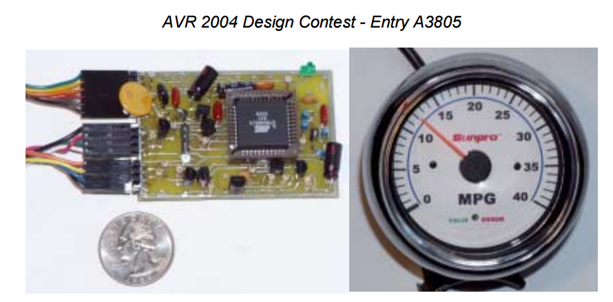
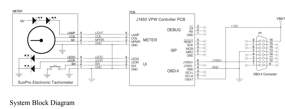
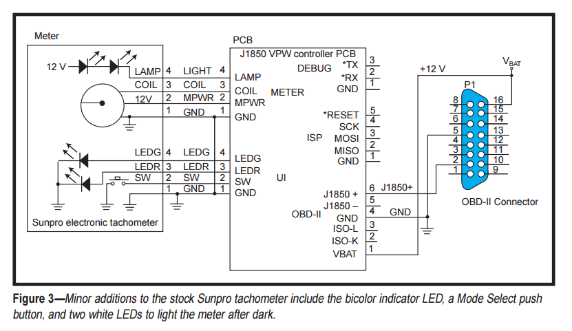
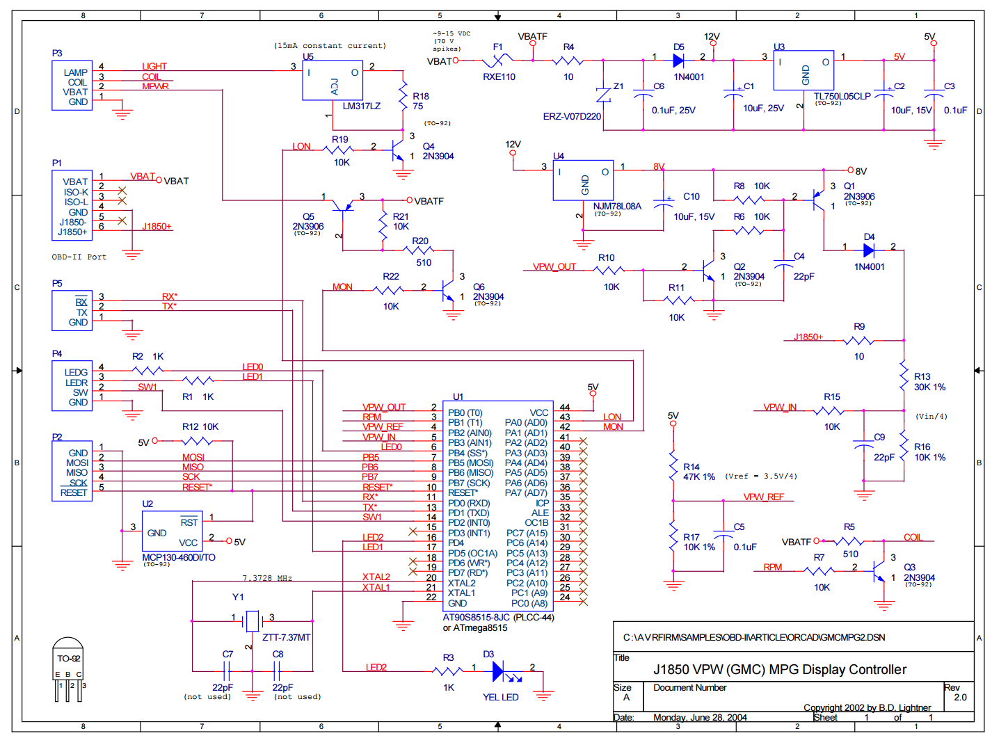
MCU INTERFACE
As you can see in Figure 4, I used an Atmel AVR AT90S8515 8-bit RISC microcontroller (U1) running at 7.3728 MHz.
Today, the ATmega8515 would be a better choice.
The ATmega8515 is 100% pin- and function-compatible with the older AT90S8515 part.
Both parts come with 8 KB of in-circuit programmable flash memory-based instruction memory,
512 bytes of SRAM, and 512 bytes of on-chip EEPROM.
The AVR RISC instruction set is well suited for programming in C and it’s extremely efficient.
In the automotive electronics design business, we sometimes refer to the automobile’s 12-V electrical bus as “the power supply from hell.”
You must pay careful attention to a number of unwritten rules when drawing power from the battery.
Ignore these rules, and your sensitive digital electronics will be doomed!
The nominally 12-V lead-acid battery in your car can vary from a low of less than 9 V
(when cold-cranking your engine with a weak battery) to more than 14 V when charging.
Sometimes that voltage even jumps up to a more or less steady 24-plus V
when the tow truck driver decides to jump-start your car with a dual 12-V battery system!
Also, be prepared for 70-plus-V noise spikes from various inductive loads attached to your vehicle’s electrical system.
Even more amazing is how bad things get if the 12-V battery is removed from the circuit.
The chemistry of the lead-acid battery itself normally quiets the nominally 12-V power bus in an automobile.
A loose battery wire or bad contact can take the battery, and its calming effects, in and out of the circuit.
Bad news indeed!
Given everything I’ve mentioned, I tend to favor the belt and suspenders approach to drawing power from an automobile’s battery.
As you can see in Figure 4, battery power (VBAT) is first fused with polysilicon fuse F1.
It’s then current limited with R4, overvoltage protected with the polysorb Z1, filtered with capacitors C6 and C1,
and reverse voltage protected with diode D5 before being used by other circuitry.
Regulated 5-V power comes from U3. The AT90S8515’s U1 is programmed in-circuit with programming connector P2.
Connector P5 provides access to the microcontroller’s UART transmit and receive pins for debugging.
External RS-232 level-shifting logic is needed in this case.
The six-pin connector P1 connects to the OBD-II bus signals, including battery power and ground.
The J1850 VPW signal is passed through currentlimiting resistor R9 before it’s divided by four using resistors R13 and R16 and filter capacitor C9.
Protection resistor R15 routes the divided input voltage to one of the microcontroller’s analog comparator pins (U1-5).
Resistors R14 and R17 and capacitor C5 provide a stable reference voltage for detecting the bit-serial input from the J1850 VPW bus
using the second analog comparator pin (U1-5).
The analog comparator’s state changes each time the J1850 VPW bus input passes through 3.5 V.
The circuit that provides active J1850 VPW pulses to the OBD-II bus starts with a regulated 8 V from U4.
This voltage is driven into the J1850 VPW bus through diode D4 and currentlimiting resistor R9 using NPN transistor Q1.
Transistor Q1 is normally biased off by pull-up resistor R8.
The NPN transistor Q2, which is biased normally off by pull-down resistor R11, level shifts the microcontroller’s 0- to 5-V digital output
to turn on Q1 whenever pin U1-2 is driven high.
The RC filter made up of R6 and C4 controls the slew rate of transistor Q1 via its base current.
When the AT90S8515 resets, transistor Q1 is off, leaving the J1850 VPW bus in a safe passive mode.
Simulated ignition coil 0- to 12-V pulses are provided by Q3, R7, and R5.
A high on the microcontroller RPM output pin U1-3 drives the COIL signal to ground,
simulating closed points in the vehicle’s distributor.
This digital output generates a pulse train at the interrupt level under the control of the AT90S8515’s 16-bit timer/counter using the CompareA and CompareB interrupts.
The microcontroller directly drives three LEDs using current-limiting 1-kΩ resistors R1, R2, and R3.
One LED is mounted on the PCB, and the other two are part of a bicolor LED assembly inside the meter housing connected via P4.
This connector also carries the signal from the momentary grounding push button switch in the meter.
Push button sensing pin U1-14 on the microcontroller is applied as an input, using an on-chip pull-up resistor.
The COIL signal and the fused raw battery voltage (VBATF) are supplied to the meter via connector P3.
The LIGHT signal is a switched, constantcurrent path to ground wired to two bright white LEDs in series with the VBATF.
Regulator U5 limits current to a constant 15 mA. The NPN transistor Q4 switches the LEDs on and off using digital output pin U1-43 (LON).
The 12 VDC power to the meter can be switched on and off using the microcontroller’s digital output MON(U1-42),
which controls the base of NPN transistor Q6.
When MON is high, Q1 pulls the base of NPN transistor Q5 low, sending battery power to the meter’s power pin P3-2.
FIRMWARE
I developed the firmware for this project in C using version 2.95.2 of the GNU C compiler GCC for AVR microcontrollers.
Development was performed in Windows using the WinAVR tool set,
which includes a complete set of the standard command-line UNIX utilities compiled for Windows,
as well as AVR-GCC, which is the AVR version of GCC, and all of its attendant programs and libraries.
The firmware for this project is relatively simple.
There are two basic functions that must be performed.
One is to repeatedly read the vehicle speed and the MAF rate from the engine computer and convert the readings into miles per gallon.
The other function involves generating a pulse train on the RPM output pin to drive per bit), delaying either 128 or 64 µs between each transition,
according to the J1850 VPW standard (see Figure 1).
After sending the trailing CRC byte, the bus is passive for 200 µs.
The vpw_recv() routine is slightly more complex because it must time out if no response from the engine computer is detected within 100 ms.
The routine begins by waiting for a 200-µs SOF pulse.
It then begins collecting bits, assembling them into bytes, and storing them in the RAM packet buffer.
The routine exits after vpw_recv() detects that the bus has remained passive for more than 200 µs.
The fuel system’s status is also read each read and display cycle, looking for open loop status.
If this state is detected, the meter setting is tweaked each read and display cycle.
This causes the miles per gallon needle to wiggle back and forth slightly around the true miles per gallon reading.
The needle wiggle provides a clear visual indication of Open Loop mode.
The bicolor LED on the meter face is controlled by the high-level AVRfirmware.
If the engine computer fails to respond to an OBD-II request, the red LED is lit.
Error-free reads light the meter’s green LED.
The third activity LED on the PCB is toggled on each time a request is made to the engine computer;
it turns off when the request is completed.
Besides displaying miles per gallon, the meter’s firmware can be configured to display many other real-time engine computer parameters
using the push button to select the data to display.
Unfortunately, the meter needs a more complex faceplate to make this information readable by anyone besides a gear head like me!
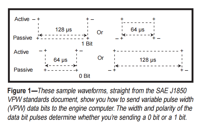
// returned status: 0 = error, 1 = OK
// buf : buffer to be sent via J1850 VPW
// n : number of bytes to sent from buf
unsigned char vpw_send( unsigned char *buf, unsigned char n )
{
  unsigned char bits, ch, timer0, period;

  wait_vpw_idle( ); // wait for idle J1850 bus

  timer0_start( T0_CK8 ); // this clears timer0 count

  vpw_active( ); // send SOF pulse
  timer0 = VPW_SOF_CNT8;
  while ( timer0_get( ) != timer0 )
    ;

  while ( n-- )                             // sent next byte in buffer
  {
    ch = *buf++;
    bits = 8;
    while ( bits-- )                        // send each bit in the byte
    {
      if ( bits & 1 )
      {
        vpw_passive( );
        period = ( ch & 0x80 ) ? VPW_LONG_CNT8 : VPW_SHORT_CNT8;
        timer0 += period / 2;               // set to delay 1/2 of period
        while ( timer0_get( ) != timer0 )
          // wait for switch
          ;
        timer0 += period - ( period / 2 );  // wait rest of period
        while ( timer0_get( ) != timer0 )
        {
          if ( is_vpw_active( ) )
            return 0;                       // collision!!
        }
      }
      else // ( bit & 1 == 0 )
      {
        vpw_active( );
        timer0 += ( ch & 0x80 ) ? VPW_SHORT_CNT8 : VPW_LONG_CNT8;
        while ( timer0_get( ) != timer0 )
          ;
      }
      ch <<= 1;
    }
  }

  vpw_passive( );                       // output EOD "symbol"
  timer0 += VPW_EOD_CNT8;
  while ( timer0_get( ) != timer0 )
    // wait for EOD complete
    ;
  return 1;
}

// returned no. bytes received
// buf : buffer to receive into buf
// max : max. bytes to receive
unsigned char vpw_recv( unsigned char *buf, unsigned char max )
{
  unsigned char n, bits, ch, delay, state;
  unsigned int num100usec;
  num100usec = 0;
  again: timer0_start( T0_CK8 );
  while ( !is_vpw_active( ) )
  {
    if ( timer0_get( ) == US2T0CNT8( 100 ) )
    {
      ++num100usec;
      timer0_start( T0_CK8 );
      if ( num100usec > 1000 )
      { // exit if >100 msec
        return 0;
      }
    }
  }
  // expect SOF
  timer0_start( T0_CK8 );
  while ( is_vpw_active( ) )
  {
    if ( timer0_get( ) == VPW_SOF_MAX_CNT8 )
      goto again;
  }

  delay = timer0_get( );
  timer0_start( T0_CK8 );
  state = is_vpw_active( );
  if ( delay < VPW_SOF_MIN_CNT8 )
    goto again;
  for ( n = 0; n < max; ++n )
  {
    bits = 8;
    ch = 0;
    while ( bits-- )
    {
      ch <<= 1;
      while ( is_vpw_active( ) == state )
      {
        if ( timer0_get( ) == VPW_SOF_MAX_CNT8 )
          return n;
      }
      delay = timer0_get( );
      timer0_start( T0_CK8 );
      state = is_vpw_active( );
      if ( delay <= VPW_BIT_MIN_CNT8 )
        goto finis;
      if ( delay > VPW_BIT_MAX_CNT8 )
        goto finis;
      ch |= ( delay > VPW_BIT_MID_CNT8 ) ? 1 : 0;
    }
    *buf++ = ch ^ 0x55;
  }
  return n;
}

// buffer with bytes to be checksumed, number of bytes
unsigned char crc8buf( unsigned char *buf, unsigned char len )
{
  unsigned char val, i, chksum;
  chksum = 0xff; // start with all one's
  while ( len-- )
  {
    i = 8;
    val = *buf++;
    while ( i-- )
    {
      if ( ( ( val ^ chksum ) & 0x80 ) != 0 )
      {
        chksum ^= 0x0e;
        chksum = ( chksum << 1 ) | 1;
      }
      else
      {
        chksum = chksum << 1;
      }
      val = val << 1;
    }
  }
  return ~chksum;
}
J1850 VPW Interface
AVR J1850 VPW interface to connect a Chrysler or GM car bus to a PC for On Board Diagnostic (OBD) monitoring.
My interface is build around Atmel AVR mega8 controller, my favourite “workhorse”.
The controller is available also in DIP package for all who not want to built with SMD components.
With 8k flash memory we have plenty of space for all kind of features.
The basic source code which supports all functions uses 3k code space.
Some features:
- SAE J1850 VPW to RS232 interface
- simple AT command control
- different Baud rates, from 9600 to 115200 Baud
- 4 different bus monitor functions
- support for 1 and 3 byte header messages
This interface was tested with firmware v1.06 and the following OBD software
- Scantool.net
- wOBD
- Scanmaster
- Digimoto
- Proscan
- OBDspy
- OBDII
Logger - Scantool
Mode 22
Use the firmware with 9600Baud and ELM322 tag for all mentioned tools.
/*************************************************************************
**  AVR J1850 VPW Interface
**  by Michael Wolf
**
**  Released under GNU GENERAL PUBLIC LICENSE
**
**  contact: webmaster@mictronics.de
**  homepage: www.mictronics.de
**
**  Revision History
**
**  when         what  who            why
**    31/12/04         v1.00 Michael    Initial release
**    21/01/05       v1.01 Michael    * changed us2cnt formula for better precision
**  05/05/05     v1.03 Michael  * changed integer types
**  08/05/05     v1.04 Michael  * changed to use Timer1
**
**************************************************************************/
#ifndef __J1850_H__
#define __J1850_H__

/*** CONFIG START ***/

#define J1850_PORT_OUT    PORTC    // J1850 output port
#define J1850_DIR_OUT     DDRC    // J1850 direction register
#define J1850_PIN_OUT        3            // J1850 output pin

#define J1850_PORT_IN        PINC    // J1850 input port
#define J1850_PULLUP_IN    PORTC    // J1850 pull-up register
#define J1850_DIR_IN         DDRC    // J1850 direction register
#define J1850_PIN_IN        0            // J1850 input pin

#define    J1850_PIN_OUT_NEG            // define output level inverted by hardware
#define    J1850_PIN_IN_NEG            // define input level inverted by hardware

/*** CONFIG END ***/

#ifdef J1850_PIN_OUT_NEG
    #define j1850_active() J1850_PORT_OUT &=~ _BV(J1850_PIN_OUT)
    #define j1850_passive() J1850_PORT_OUT |= _BV(J1850_PIN_OUT)
#else
    #define j1850_active() J1850_PORT_OUT |= _BV(J1850_PIN_OUT)
    #define j1850_passive() J1850_PORT_OUT &=~ _BV(J1850_PIN_OUT)
#endif

#ifdef J1850_PIN_IN_NEG
#define is_j1850_active() bit_is_clear(J1850_PORT_IN, J1850_PIN_IN)
#else
#define is_j1850_active() bit_is_set(J1850_PORT_IN, J1850_PIN_IN)
#endif

/* Define Timer1 Prescaler here */
#define c_start_pulse_timer    0x01  // Timer1 runs without Prescaler, 135ns tick @ 7,3728MHz
#define c_stop_pulse_timer    0x00


// define error return codes
#define J1850_RETURN_CODE_UNKNOWN    0
#define J1850_RETURN_CODE_OK         1
#define J1850_RETURN_CODE_BUS_BUSY   2
#define J1850_RETURN_CODE_BUS_ERROR  3
#define J1850_RETURN_CODE_DATA_ERROR 4
#define J1850_RETURN_CODE_NO_DATA    5
#define J1850_RETURN_CODE_DATA       6

// convert microseconds to counter values
#define us2cnt(us) ((unsigned int)((unsigned long)(us) / (1000000L / (float)((unsigned long)MCU_XTAL / 1L))))

#define WAIT_100us    us2cnt(100)        // 100us, used to count 100ms

// define J1850 VPW timing requirements in accordance with SAE J1850 standard
// all pulse width times in us
// transmitting pulse width
#define TX_SHORT    us2cnt(64)        // Short pulse nominal time
#define TX_LONG        us2cnt(128)        // Long pulse nominal time
#define TX_SOF        us2cnt(200)        // Start Of Frame nominal time
#define TX_EOD        us2cnt(200)        // End Of Data nominal time
#define TX_EOF        us2cnt(280)        // End Of Frame nominal time
#define TX_BRK        us2cnt(300)        // Break nominal time
#define TX_IFS        us2cnt(300)        // Inter Frame Separation nominal time

// see SAE J1850 chapter 6.6.2.5 for preferred use of In Frame Respond/Normalization pulse
#define TX_IFR_SHORT_CRC    us2cnt(64)    // short In Frame Respond, IFR contain CRC
#define TX_IFR_LONG_NOCRC us2cnt(128)    // long In Frame Respond, IFR contain no CRC

// receiving pulse width
#define RX_SHORT_MIN    us2cnt(34)    // minimum short pulse time
#define RX_SHORT_MAX    us2cnt(96)    // maximum short pulse time
#define RX_LONG_MIN        us2cnt(96)    // minimum long pulse time
#define RX_LONG_MAX        us2cnt(163)    // maximum long pulse time
#define RX_SOF_MIN        us2cnt(163)    // minimum start of frame time
#define RX_SOF_MAX        us2cnt(239)    // maximum start of frame time
#define RX_EOD_MIN        us2cnt(163)    // minimum end of data time
#define RX_EOD_MAX        us2cnt(239)    // maximum end of data time
#define RX_EOF_MIN        us2cnt(239)    // minimum end of frame time, ends at minimum IFS
#define RX_BRK_MIN        us2cnt(239)    // minimum break time
#define RX_IFS_MIN        us2cnt(280)    // minimum inter frame separation time, ends at next SOF

// see chapter 6.6.2.5 for preferred use of In Frame Respond/Normalization pulse
#define RX_IFR_SHORT_MIN    us2cnt(34)        // minimum short in frame respond pulse time
#define RX_IFR_SHORT_MAX    us2cnt(96)        // maximum short in frame respond pulse time
#define RX_IFR_LONG_MIN        us2cnt(96)        // minimum long in frame respond pulse time
#define RX_IFR_LONG_MAX        us2cnt(163)        // maximum long in frame respond pulse time

uint8_t timeout_multiplier;  // default 4ms timeout multiplier

extern void j1850_init(void);
extern uint8_t j1850_recv_msg(uint8_t *msg_buf );
extern uint8_t j1850_send_msg(uint8_t *msg_buf, int8_t nbytes);
extern uint8_t j1850_crc(uint8_t *msg_buf, int8_t nbytes);

static inline void timer1_ctrl(uint8_t val)
{
    TCCR1B = val;
}

static inline void timer1_start(void)
{
    TCCR1B = c_start_pulse_timer;
    TCNT1 = 0;
}

static inline void timer1_stop(void)
{
    TCCR1B = c_stop_pulse_timer;
}

static inline void timer1_set(uint16_t val)
{
    TCNT1 = val;
}

#endif // __J1850_H__
/*************************************************************************
 **  AVR J1850 VPW Interface
 **  by Michael Wolf
 **
 **  Released under GNU GENERAL PUBLIC LICENSE
 **
 **  contact: webmaster@mictronics.de
 **  homepage: www.mictronics.de
 **
 **  Revision History
 **
 **  when         what  who      why
 **  31/12/04     v1.00 Michael  Initial release
 **  07/01/05     v1.01 Michael  * changed timeout in j1850_recv_msg() to 4ms
 **                                use an external timeout loop to call the function
 **                                25 times maximum to get the requirment of 100ms
 **  05/05/05     v1.03 Michael  * changed integer types
 **  08/05/05     v1.04 Michael  * changed to use Timer1
 **  11/08/05     v1.05 Michael  * changed EOD to EOF after last databyte send
 **  10/10/06     v1.06 Michael  * changed timeout in j1850_recv_msg() back to 100us
 **  08/09/10     v1.07 Michael  * fix an possible issue with TCNT1 when code is ported
 **
 **  NOTE:
 **  This file is based on code from Bruce D. Lightner.
 **  (lightner AT lightner DOT net)
 **  This code is part of his project at
 **  http://www.circuitcellar.com/avr2004/first.html
 **  The code is modified and reworked to remove all "GOTO's" and
 **  deprecated macros to be compatible with the latest version of WinAVR.
 **************************************************************************/
#include <avr/io.h>
#include "j1850.h"
/*
 **---------------------------------------------------------------------------
 **
 ** Abstract: Init J1850 bus driver
 **
 ** Parameters: none
 **
 ** Returns: none
 **
 **---------------------------------------------------------------------------
 */
void j1850_init( void )
{
  j1850_passive( );  // set VPW pin in passive state
  J1850_DIR_OUT |= _BV( J1850_PIN_OUT );  // make VPW output pin an output

  J1850_PULLUP_IN |= _BV( J1850_PIN_IN ); // enable pull-up on VPW pin
  J1850_DIR_IN &= ~_BV( J1850_PIN_IN );  // make VPW input pin an input

}

/*
 **---------------------------------------------------------------------------
 **
 ** Abstract: Wait for J1850 bus idle
 **
 ** Parameters: none
 **
 ** Returns: none
 **
 **---------------------------------------------------------------------------
 */
static void j1850_wait_idle( void )
{
  timer1_start( );
  while ( TCNT1 < RX_IFS_MIN ) // wait for minimum IFS symbol
  {
    if ( is_j1850_active( ) )
      timer1_start( ); // restart timer1 when bus not idle
  }
}

/*
 **---------------------------------------------------------------------------
 **
 ** Abstract: Receive J1850 frame (max 12 bytes)
 **
 ** Parameters: Pointer to frame buffer
 **
 ** Returns: Number of received bytes OR in case of error, error code with
 **          bit 7 set as error indication
 **
 **---------------------------------------------------------------------------
 */
uint8_t j1850_recv_msg( uint8_t *msg_buf )
{
  uint8_t nbits;      // bit position counter within a byte
  uint8_t nbytes;   // number of received bytes
  uint8_t bit_state;   // used to compare bit state, active or passive
  /*
   wait for responds
   */

  timer1_start( );
  while ( !is_j1850_active( ) ) // run as long bus is passive (IDLE)
  {
    if ( TCNT1 >= WAIT_100us ) // check for 100us
    {
      timer1_stop( );
      return J1850_RETURN_CODE_NO_DATA | 0x80; // error, no responds within 100us
    }
  }

  // wait for SOF
  timer1_start( ); // restart timer1
  while ( is_j1850_active( ) ) // run as long bus is active (SOF is an active symbol)
  {
    if ( TCNT1 >= RX_SOF_MAX )
      return J1850_RETURN_CODE_BUS_ERROR | 0x80; // error on SOF timeout
  }

  timer1_stop( );
  if ( TCNT1 < RX_SOF_MIN )
    return J1850_RETURN_CODE_BUS_ERROR | 0x80; // error, symbole was not SOF

  bit_state = is_j1850_active( );  // store actual bus state
  timer1_start( );
  for ( nbytes = 0; nbytes < 12; ++nbytes )
  {
    nbits = 8;
    do
    {
      *msg_buf <<= 1;
      while ( is_j1850_active( ) == bit_state ) // compare last with actual bus state, wait for change
      {
        if ( TCNT1 >= RX_EOD_MIN ) // check for EOD symbol
        {
          timer1_stop( );
          return nbytes;  // return number of received bytes
        }
      }
      bit_state = is_j1850_active( );  // store actual bus state
      uint16_t tcnt1_buf = TCNT1;
      timer1_start( );
      if ( tcnt1_buf < RX_SHORT_MIN )
        return J1850_RETURN_CODE_BUS_ERROR | 0x80;  // error, pulse was to short

      // check for short active pulse = "1" bit
      if ( ( tcnt1_buf < RX_SHORT_MAX ) && !is_j1850_active( ) )
        *msg_buf |= 1;

      // check for long passive pulse = "1" bit
      if ( ( tcnt1_buf > RX_LONG_MIN ) && ( tcnt1_buf < RX_LONG_MAX )
        && is_j1850_active( ) )
        *msg_buf |= 1;

    }while ( --nbits );  // end 8 bit while loop

    ++msg_buf;  // store next byte

  } // end 12 byte for loop

  // return after a maximum of 12 bytes
  timer1_stop( );
  return nbytes;
}

/*
 **---------------------------------------------------------------------------
 **
 ** Abstract: Send J1850 frame (maximum 12 bytes)
 **
 ** Parameters: Pointer to frame buffer, frame length
 **
 ** Returns: 0 = error
 **          1 = OK
 **
 **---------------------------------------------------------------------------
 */
uint8_t j1850_send_msg( uint8_t *msg_buf, int8_t nbytes )
{
  if ( nbytes > 12 )
    return J1850_RETURN_CODE_DATA_ERROR; // error, message to long, see SAE J1850

  j1850_wait_idle( );  // wait for idle bus

  timer1_start( );
  j1850_active( ); // set bus active

  while ( TCNT1 < TX_SOF )
    ;  // transmit SOF symbol

  uint8_t temp_byte,  // temporary byte store
      nbits;    // bit position counter within a byte

  uint16_t delay;   // bit delay time

  do
  {
    temp_byte = *msg_buf; // store byte temporary
    nbits = 8;
    while ( nbits-- )   // send 8 bits
    {
      if ( nbits & 1 ) // start allways with passive symbol
      {
        j1850_passive( );  // set bus passive
        timer1_start( );
        delay = ( temp_byte & 0x80 ) ? TX_LONG : TX_SHORT; // send correct pulse lenght
        while ( TCNT1 <= delay )  // wait
        {
          if ( !J1850_PORT_IN & _BV( J1850_PIN_IN ) )  // check for bus error
          {
            timer1_stop( );
            return J1850_RETURN_CODE_BUS_ERROR; // error, bus collision!
          }
        }
      }
      else  // send active symbol
      {
        j1850_active( ); // set bus active
        timer1_start( );
        delay = ( temp_byte & 0x80 ) ? TX_SHORT : TX_LONG; // send correct pulse lenght
        while ( TCNT1 <= delay )
          ; // wait
        // no error check needed, ACTIVE dominates
      }
      temp_byte <<= 1;  // next bit
    }  // end nbits while loop
    ++msg_buf;  // next byte from buffer
  }while ( --nbytes );  // end nbytes do loop

  j1850_passive( );  // send EOF symbol
  timer1_start( );
  while ( TCNT1 <= TX_EOF )
    ; // wait for EOF complete
  timer1_stop( );
  return J1850_RETURN_CODE_OK;  // no error
}

/*
 **---------------------------------------------------------------------------
 **
 ** Abstract: Calculate J1850 CRC
 **
 ** Parameters: Pointer to frame buffer, frame length
 **
 ** Returns: CRC of frame
 **
 **---------------------------------------------------------------------------
 */
// calculate J1850 message CRC
uint8_t j1850_crc( uint8_t *msg_buf, int8_t nbytes )
{
  uint8_t crc_reg = 0xff, poly, byte_count, bit_count;
  uint8_t *byte_point;
  uint8_t bit_point;

  for ( byte_count = 0, byte_point = msg_buf; byte_count < nbytes;
      ++byte_count, ++byte_point )
  {
    for ( bit_count = 0, bit_point = 0x80; bit_count < 8;
        ++bit_count, bit_point >>= 1 )
    {
      if ( bit_point & *byte_point )  // case for new bit = 1
      {
        if ( crc_reg & 0x80 )
          poly = 1; // define the polynomial
        else
          poly = 0x1c;
        crc_reg = ( ( crc_reg << 1 ) | 1 ) ^ poly;
      }
      else    // case for new bit = 0
      {
        poly = 0;
        if ( crc_reg & 0x80 )
          poly = 0x1d;
        crc_reg = ( crc_reg << 1 ) ^ poly;
      }
    }
  }
  return ~crc_reg;  // Return CRC
}
/*************************************************************************
**  AVR J1850 VPW Interface
**  by Michael Wolf
**
**  Released under GNU GENERAL PUBLIC LICENSE
**
**  contact: webmaster@mictronics.de
**  homepage: www.mictronics.de
**
**  Revision History
**
**  when         what  who            why
**    31/12/04         v1.00 Michael    Initial release
**  05/05/05     v1.01 Michael  * changed integer types
**  19/08/05     v1.02 Michael  * changed status messages
**                              + added ELM322 ID tag
**
**************************************************************************/
#ifndef __MAIN_H__
#define __MAIN_H__

// Set default RS232 baud rate
#define BAUD_RATE    115200

// J1850 message (max 12 byte - 3 byte header - 1 CRC byte) x 2
// because of 2 ASCII chars/byte + 1 terminator
// or 10 bytes for AT command
#define SERIAL_MSG_BUF_SIZE    18

const char ident_txt[]    PROGMEM = "AVR-J1850 VPW v1.07\n\r" __DATE__" / "__TIME__"\n\r\n\r";
//const char ident_txt[]    PROGMEM = "ELM322 v2.0\r\n\r\n";

const char bus_busy_txt[]   PROGMEM = "BUSBUSY\r\n";
const char bus_error_txt[]  PROGMEM = "BUSERROR\r\n";
const char data_error_txt[] PROGMEM = "<DATAERROR\r\n";
const char no_data_txt[]    PROGMEM = "NO DATA\r\n";

// define bit macros
#define SETBIT(x,y) (x |= (y))         // Set bit y in byte x
#define CLEARBIT(x,y) (x &= (~y)) // Clear bit y in byte x
#define CHECKBIT(x,y) (x & (y))     // Check bit y in byte x

// define parameter bit mask constants
#define ECHO           0x0001 // bit 0 : Echo on/off
#define HEADER      0x0002 // bit 1 : Headers on/off
#define LINEFEED  0x0004 // bit 2 : Linefeeds on/off
#define RESPONSE  0x0008 // bit 3 : Responses on/off
#define PACKED    0x0010 // bit 4 : use packed data
#define AUTO_RECV 0x0020 // bit 5 : auto receive on/off
#define MON_TX        0x0040 // bit 6 : monitor transmitter
#define MON_RX        0x0080 // bit 7 : monitor receiver
#define MON_OBH   0x0100 // bit 8 : monitor one byte header
#define USE_OBH   0x0200 // bit 9 : use one byte header in Tx message

// use of bit-mask for parameters init to default values
volatile uint16_t parameter_bits = ECHO|LINEFEED|RESPONSE|AUTO_RECV;

uint8_t j1850_req_header[3] = {0x68, 0x6A, 0xF1};  // default request header
uint8_t auto_recv_addr = 0x6B;  // physical or functional address in receive mode
uint8_t mon_receiver;  // monitor receiver only addr
uint8_t mon_transmitter;  // monitor transmitter only addr

uint8_t serial_msg_buf[SERIAL_MSG_BUF_SIZE];     // serial Rx buffer
uint8_t *serial_msg_pntr;

int16_t serial_putc(int8_t data);    // send one databyte to USART
void serial_put_byte2ascii(uint8_t val);
void serial_puts_P(const char *s);
int8_t serial_processing(void);
void ident(void);
void print_prompt(void);

#define DEFAULT_BAUD   ((unsigned int)((unsigned long)MCU_XTAL/((unsigned long)BAUD_RATE*16)-1))    // calculate baud rate value for UBBR

#define BAUD_9600   ((unsigned int)((unsigned long)MCU_XTAL/((unsigned long)9600*16)-1))
#define BAUD_14400   ((unsigned int)((unsigned long)MCU_XTAL/((unsigned long)14400*16)-1))
#define BAUD_19200   ((unsigned int)((unsigned long)MCU_XTAL/((unsigned long)19200*16)-1))
#define BAUD_28800   ((unsigned int)((unsigned long)MCU_XTAL/((unsigned long)28800*16)-1))
#define BAUD_38400   ((unsigned int)((unsigned long)MCU_XTAL/((unsigned long)38400*16)-1))
#define BAUD_57600   ((unsigned int)((unsigned long)MCU_XTAL/((unsigned long)57600*16)-1))

#endif // __MAIN_H__
/************************************************************************* ** AVR J1850 VPW Interface ** by Michael Wolf ** ** Released under GNU GENERAL PUBLIC LICENSE ** ** contact: webmaster@mictronics.de ** homepage: www.mictronics.de ** ** Revision History ** ** when what who why ** 31/12/04 v1.00b Michael Initial release ** This is a beta version, some changes and ** improvments needs must be made for future ** versions. ** 07/01/05 v1.01 Michael + added correct no data timeout handling ** * watchdog will force a reset on AT Z ** 10/05/05 v1.04 Michael - fixed bug in received message error checking ** * changed integer types ** + added command AT MI to monitor frames with one ** byte header ** + added command AT Ox to enable/disable one ** byte header messages ** - fixed bug for AT M... messages ** + added command AT Bx to set Baud rates ** 04/06/05 v1.05 Michael - fixed bug in one/three byte header Tx selection ** 19/08/05 v1.06 Michael + added prompt output after data ** 10/10/06 v1.07 Michael * changed timeout handling for j1850_recv_msg() ** ** Used develompent tools (download @ www.avrfreaks.net): ** Programmers Notepad v2.0.5.32 ** WinAVR (GCC) 3.4.1 ** AvrStudio4 for simulating and debugging ** ** [ Legend: ] ** [ + Added feature ] ** [ * Improved/changed feature ] ** [ - Bug fixed (I hope) ] ** ** ToDo: ** - tweak source code ** - add transparent mode ** - add 4x mode ** - add block transmit mode ** **************************************************************************/ #include <stdint.h> #include <string.h> #include <avr/io.h> #include <avr/interrupt.h> #include <avr/pgmspace.h> #include <avr/wdt.h> #include <ctype.h> #include "main.h" #include "j1850.h" /* **--------------------------------------------------------------------------- ** ** Abstract: Main routine ** ** ** Parameters: none ** ** ** Returns: NULL ** ** **--------------------------------------------------------------------------- */ // main routine int16_t main( void ) { wdt_disable(); // make sure the watchdog is not running UBRRH = DEFAULT_BAUD>>8; // set baud rate UBRRL = DEFAULT_BAUD; UCSRB =((1<<RXCIE)|(1<<RXEN)|(1<<TXEN)); // enable Rx & Tx, enable Rx interrupt UCSRC =((1<<URSEL)|(1<<UCSZ1)|(1<<UCSZ0)); // config USART; 8N1 serial_msg_pntr = &serial_msg_buf[0]; // init serial msg pointer j1850_init(); // init J1850 bus ident(); // send identification to terminal serial_putc('>'); // send initial command prompt sei(); // enable global interrupts for(;;) { while( CHECKBIT(parameter_bits, MON_RX) || CHECKBIT(parameter_bits, MON_TX) || CHECKBIT(parameter_bits, MON_OBH) ) { uint8_t j1850_msg_buf[12]; // J1850 message buffer uint8_t *j1850_msg_pntr = &j1850_msg_buf[0]; // msg pointer int8_t recv_nbytes; // byte counter recv_nbytes = j1850_recv_msg(j1850_msg_buf); // get J1850 frame if( !(recv_nbytes & 0x80) ) // proceed only with no errors { j1850_msg_pntr = &j1850_msg_buf[0]; // check for respond from correct addr or monitor all mode if( (CHECKBIT(parameter_bits, MON_RX) && CHECKBIT(parameter_bits, MON_TX)) || ((mon_receiver == *(j1850_msg_pntr+1)) && CHECKBIT(parameter_bits, MON_RX) ) || ((mon_transmitter == *(j1850_msg_pntr+2)) && CHECKBIT(parameter_bits, MON_TX) ) || ((mon_transmitter == *(j1850_msg_pntr)) && CHECKBIT(parameter_bits, MON_OBH) ) ) { // surpess CRC and header bytes output if( !CHECKBIT(parameter_bits, HEADER) ) { if( CHECKBIT(parameter_bits, MON_OBH) || // check if one byte header frames are used CHECKBIT(parameter_bits, USE_OBH) ) { recv_nbytes -= 2; // discard 1st header byte and CRC j1850_msg_pntr += 1; // skip header byte } else { recv_nbytes -= 4; // discard 3 header bytes and CRC j1850_msg_pntr += 3; // skip 3 header bytes } } if(CHECKBIT(parameter_bits, PACKED)) { // check respond CRC if( *(j1850_msg_pntr+(recv_nbytes-1)) == j1850_crc(j1850_msg_buf, recv_nbytes-1) ) serial_putc(recv_nbytes); // length byte else serial_putc(recv_nbytes&0x80); // length byte with error indicator set } // output response data for(;recv_nbytes > 0; recv_nbytes--) { if(CHECKBIT(parameter_bits, PACKED)) serial_putc(*j1850_msg_pntr++); // data byte else { serial_put_byte2ascii(*j1850_msg_pntr++); serial_putc(' '); } } if(!CHECKBIT(parameter_bits, PACKED)) {// formated output with CR and optional LF serial_putc('\r'); if(CHECKBIT(parameter_bits, LINEFEED)) serial_putc('\n'); } } // end if valid monitoring addr } // end if message recv } // end while monitoring active } // endless loop return 0; } // end of main() /* **--------------------------------------------------------------------------- ** ** Abstract: Send program ident string to terminal ** ** ** Parameters: none ** ** ** Returns: none ** ** **--------------------------------------------------------------------------- */ void ident(void) { serial_puts_P(ident_txt); // show code description } /* **--------------------------------------------------------------------------- ** ** Abstract: Convert 2 byte ASCII hex to 1 byte decimal ** ** ** Parameters: Pointer to first ASCII char ** ** ** Returns: decimal value ** ** **--------------------------------------------------------------------------- */ static uint8_t ascii2byte(char *val) { uint8_t temp = *val; if(temp > 0x60) temp -= 39; // convert chars a-f temp -= 48; // convert chars 0-9 temp *= 16; temp += *(val+1); if(*(val+1) > 0x60) temp -= 39; // convert chars a-f temp -= 48; // convert chars 0-9 return temp; } /* **--------------------------------------------------------------------------- ** ** Abstract: Processing of received serial string ** ** Parameters: none ** ** Returns: 0 = unknown ** 1 = OK ** 2 = bus busy ** 3 = bus error ** 4 = data error ** 5 = no data ** 6 = data ( also to surpress any other output ) ** **--------------------------------------------------------------------------- */ int8_t serial_processing(void) { char *serial_msg_pntr = strlwr((char *)serial_msg_buf); // convert string to lower uint8_t serial_msg_len = strlen((char *)serial_msg_buf); // get string length uint8_t *var_pntr = 0; // point to different variables if( (*(serial_msg_pntr)=='a') && (*(serial_msg_pntr+1)=='t')) // check for "at" or hex { // is AT command // AT command found switch( *(serial_msg_pntr+2) ) // switch on "at" command { case 'a': // auto receive address on if(*(serial_msg_pntr+3) == 'r') SETBIT(parameter_bits, AUTO_RECV); if( j1850_req_header[0] & 0x04) // check for functional or physical addr auto_recv_addr = j1850_req_header[2]; // use physical recv addr else auto_recv_addr = j1850_req_header[1]+1; // use funct recv addr return J1850_RETURN_CODE_OK ; case 'b': // set Baud rate if( isdigit(*(serial_msg_pntr+3)) ) { switch(*(serial_msg_pntr+3)) { case '0': UBRRH = BAUD_9600>>8; // set 9600 Baud UBRRL = BAUD_9600; break; case '1': UBRRH = BAUD_14400>>8; // set 14.4k Baud UBRRL = BAUD_14400; break; case '2': UBRRH = BAUD_19200>>8; // set 19.2k Baud UBRRL = BAUD_19200; break; case '3': UBRRH = BAUD_28800>>8; // set 28.8k Baud UBRRL = BAUD_28800; break; case '4': UBRRH = BAUD_38400>>8; // set 38.4k Baud UBRRL = BAUD_38400; break; case '5': UBRRH = BAUD_57600>>8; // set 57.6k Baud UBRRL = BAUD_57600; break; default: UBRRH = DEFAULT_BAUD>>8; // set default baud rate UBRRL = DEFAULT_BAUD; } return J1850_RETURN_CODE_OK ; } return J1850_RETURN_CODE_UNKNOWN; case 'd': // set defaults parameter_bits = ECHO|LINEFEED|RESPONSE|AUTO_RECV; timeout_multiplier = 0x19; // set default timeout to 4ms * 25 = 100ms j1850_req_header[0] = 0x68; // Prio 3, Functional Adressing j1850_req_header[1] = 0x6A; // Target legislated diagnostic j1850_req_header[2] = 0xF1; // Frame source = Diagnostic Tool return J1850_RETURN_CODE_OK ; case 'e': // echo on/off if(*(serial_msg_pntr+3) == '0') CLEARBIT(parameter_bits, ECHO); else SETBIT(parameter_bits, ECHO); return J1850_RETURN_CODE_OK ; case 'i': // send ident string ident(); return J1850_RETURN_CODE_OK ; case 'l': // linefeed on/off (only for data strings) if(*(serial_msg_pntr+3) == '0') CLEARBIT(parameter_bits, LINEFEED); else SETBIT(parameter_bits, LINEFEED); return J1850_RETURN_CODE_OK ; case 'h': // show headers on/off if(*(serial_msg_pntr+3) == '0') CLEARBIT(parameter_bits, HEADER); else SETBIT(parameter_bits, HEADER); return J1850_RETURN_CODE_OK ; case 'r': // show response on/off if(*(serial_msg_pntr+3) == '0') CLEARBIT(parameter_bits, RESPONSE); else SETBIT(parameter_bits, RESPONSE); return J1850_RETURN_CODE_OK ; case 'f': // send formated if(*(serial_msg_pntr+3) == 'd') CLEARBIT(parameter_bits, PACKED); return J1850_RETURN_CODE_OK ; case 'o': // one byte header on/off if(*(serial_msg_pntr+3) == '0') CLEARBIT(parameter_bits, USE_OBH); else SETBIT(parameter_bits, USE_OBH); return J1850_RETURN_CODE_OK ; case 'p': // send packed data if(*(serial_msg_pntr+3) == 'd') SETBIT(parameter_bits, PACKED); return J1850_RETURN_CODE_OK ; case 'm': // switch into monitoring mode switch(*(serial_msg_pntr+3)) { case 'a': SETBIT(parameter_bits, MON_RX); // monitor all SETBIT(parameter_bits, MON_TX); return J1850_RETURN_CODE_DATA; // return, no following parameter case 'i': CLEARBIT(parameter_bits, MON_TX); CLEARBIT(parameter_bits, MON_RX); SETBIT(parameter_bits, MON_OBH); // monitor one byte header var_pntr = &mon_transmitter; break; // get folowing parameter case 'r': // monitor only receiver addr SETBIT(parameter_bits, MON_RX); // monitor receiver only CLEARBIT(parameter_bits, MON_TX); var_pntr = &mon_receiver; break; // get following parameter case 't': // monitor only transmitter addr CLEARBIT(parameter_bits, MON_RX); SETBIT(parameter_bits, MON_TX); // monitor transmitter only var_pntr = &mon_transmitter; break; // get following parameter default: return J1850_RETURN_CODE_UNKNOWN; } if( isxdigit(*(serial_msg_pntr+4)) && isxdigit(*(serial_msg_pntr+5)) && ( serial_msg_len == 6) ) // proceed when next two chars are hex { // make 1 byte hex from 2 chars ASCII and save *var_pntr = ascii2byte(serial_msg_pntr+4); return J1850_RETURN_CODE_DATA; } case 's': // commands SH,SR or ST if( isxdigit(*(serial_msg_pntr+4)) && isxdigit(*(serial_msg_pntr+5)) ) { // proceed when next two chars are hex switch(*(serial_msg_pntr+3)) { case 'h': // set header bytes if( isxdigit(*(serial_msg_pntr+6)) && isxdigit(*(serial_msg_pntr+7)) && isxdigit(*(serial_msg_pntr+8)) && isxdigit(*(serial_msg_pntr+9)) && ( serial_msg_len == 10) ) // proceed when next four chars are hex { // make 3 byte hex from 6 chars ASCII and save j1850_req_header[0]=ascii2byte(serial_msg_pntr+4); j1850_req_header[1]=ascii2byte(serial_msg_pntr+6); j1850_req_header[2]=ascii2byte(serial_msg_pntr+8); if( CHECKBIT(parameter_bits, AUTO_RECV) ) { if( j1850_req_header[0] & 0x04) // check for functional or physical addr auto_recv_addr = j1850_req_header[2]; // use physical recv addr else auto_recv_addr = j1850_req_header[1]+1; // use funct recv addr } return J1850_RETURN_CODE_OK ; } break; case 't': // set response timeout multipler var_pntr = &timeout_multiplier; break; case 'r': // set receive address and manual receive mode var_pntr = &auto_recv_addr; CLEARBIT(parameter_bits, AUTO_RECV); break; default: return J1850_RETURN_CODE_UNKNOWN; } // end switch char 3 if(serial_msg_len == 6) { *var_pntr =ascii2byte(serial_msg_pntr+4); if (timeout_multiplier < 8) timeout_multiplier = 8; // set multiplier for minimum of 32ms timout return J1850_RETURN_CODE_OK ; } } // end if char 4 and 5 isxdigit return J1850_RETURN_CODE_UNKNOWN; case 'z': // reset all and restart device wdt_enable(WDTO_15MS); // enable watdog timeout 15ms for(;;); // wait for watchdog reset default: // return error, unknown command return J1850_RETURN_CODE_UNKNOWN; } } else { // is OBD hex command // no AT found, must be HEX code if( (serial_msg_len & 1) || (serial_msg_len > 16) ) // check for "even" message lenght return J1850_RETURN_CODE_UNKNOWN; // and maximum of 8 data bytes serial_msg_len /= 2; // use half the string lenght for byte count while( *serial_msg_pntr ) // check all chars are valid hex chars { if(!isxdigit(*serial_msg_pntr)) return J1850_RETURN_CODE_UNKNOWN; ++serial_msg_pntr; } serial_msg_pntr = (char *)&serial_msg_buf[0]; // reset pointer uint8_t j1850_msg_buf[12]; // J1850 message to be send uint8_t *j1850_msg_pntr = &j1850_msg_buf[0]; // msg pointer uint8_t cnt; // byte counter // store header bytes 1, use at least one header byte *j1850_msg_pntr = j1850_req_header[0]; // store header 2-3 when three byte header is in use if( !CHECKBIT(parameter_bits, USE_OBH) ) { *(++j1850_msg_pntr) = j1850_req_header[1]; *(++j1850_msg_pntr) = j1850_req_header[2]; } // convert serial message from 2 byte ASCII to 1 byte binary and store for(cnt = 0; cnt < serial_msg_len; ++cnt) { *(++j1850_msg_pntr) = ascii2byte(serial_msg_pntr); serial_msg_pntr += 2; } // generate CRC for J1850 message and store, use 1 or 3 byte header if(CHECKBIT(parameter_bits, USE_OBH)) *(++j1850_msg_pntr) = j1850_crc( j1850_msg_buf,serial_msg_len+1 ); // use one header bytes else *(++j1850_msg_pntr) = j1850_crc( j1850_msg_buf,serial_msg_len+3 ); // use three header byte // send J1850 message and save return code, use 1 or 3 byte header uint8_t return_code; if(CHECKBIT(parameter_bits, USE_OBH)) return_code = j1850_send_msg(j1850_msg_buf, serial_msg_len+2); else return_code = j1850_send_msg(j1850_msg_buf, serial_msg_len+4); // skip receive in case of transmit error or RESPONSE disabled if( (return_code == J1850_RETURN_CODE_OK) && CHECKBIT(parameter_bits, RESPONSE) ) { uint16_t time_count = 0; do { /* Run this loop until we received a valid response frame, or response timed out, or the bus was idle for 100ms or an bus error occured. */ cnt = j1850_recv_msg(j1850_msg_buf); // receive J1850 respond /* the j1850_recv_msg() has a timeout of 100us so the loop will run 100ms by default before timeout 100ms is recommended by SAE J1850 spec */ ++time_count; if(time_count >= 1000) return J1850_RETURN_CODE_NO_DATA; /* Check for bus error. End the loop then. */ if( cnt == (J1850_RETURN_CODE_BUS_ERROR & 0x80) ) // check if we got an error code or just number of recv bytes { if(CHECKBIT(parameter_bits, PACKED)) { serial_putc(0x80); // lenght byte with error indicator set return J1850_RETURN_CODE_DATA; // surpress any other output } else return cnt & 0x7F; // return "receive message" error code } j1850_msg_pntr = &j1850_msg_buf[0]; } while( auto_recv_addr != *(j1850_msg_pntr+1) ); // check respond CRC if( *(j1850_msg_pntr+(cnt-1)) != j1850_crc(j1850_msg_buf, cnt-1) ) { if(CHECKBIT(parameter_bits, PACKED)) { serial_putc(0x80); // length byte with error indicator set return J1850_RETURN_CODE_DATA; // surpress any other output } else return J1850_RETURN_CODE_DATA_ERROR; } // check for respond from correct addr in auto or man recv mode if( auto_recv_addr != *(j1850_msg_pntr+1) ) { if(CHECKBIT(parameter_bits, PACKED)) { serial_putc(0x00); // length byte return J1850_RETURN_CODE_DATA; // surpress any other output } else return J1850_RETURN_CODE_NO_DATA; } if( !CHECKBIT(parameter_bits, HEADER) ) { if(CHECKBIT(parameter_bits, USE_OBH) ) // check if one byte header frames are used { cnt -= 2; // discard 1st header byte and CRC j1850_msg_pntr += 1; // skip header byte } else { cnt -= 4; // discard 3 header bytes and CRC j1850_msg_pntr += 3; // skip 3 header bytes } } if(CHECKBIT(parameter_bits, PACKED)) serial_putc(cnt); // length byte // output response data for(;cnt > 0; --cnt) { if(CHECKBIT(parameter_bits, PACKED)) serial_putc(*j1850_msg_pntr++); // length byte else { serial_put_byte2ascii(*j1850_msg_pntr++); serial_putc(' '); } } if(!CHECKBIT(parameter_bits, PACKED)) {// formated output with CR and optional LF serial_putc('\r'); if(CHECKBIT(parameter_bits, LINEFEED)) serial_putc('\n'); } return J1850_RETURN_CODE_DATA; // surpress any other output } // end if J1850 OK && RESPONSE else // transmit error or show RESPONSE OFF, return error code return return_code; } // end if !AT // we should never reach this return return J1850_RETURN_CODE_UNKNOWN; } // end serial_processing /* **--------------------------------------------------------------------------- ** ** Abstract: Send one byte via USART ** ** Parameters: data byte ** ** Returns: NULL ** **--------------------------------------------------------------------------- */ int16_t serial_putc(int8_t data) { // wait for USART to become available while ( (UCSRA & _BV(UDRE)) != _BV(UDRE)); UDR = data; // send character return 0; }; //end usart_putc /* **--------------------------------------------------------------------------- ** ** Abstract: Make 2 byte ASCII from one byte binary and send to terminal ** ** Parameters: input byte ** ** Returns: none ** **--------------------------------------------------------------------------- */ void serial_put_byte2ascii(uint8_t val) { uint8_t ascii1=val; serial_putc( ((ascii1>>4) < 10) ? (ascii1>>4) + 48 : (ascii1>>4) + 55 ); // upper nibble serial_putc( ((val&0x0f) < 10) ? (val&0x0f) + 48 : (val&0x0f) + 55 ); // lower nibble } /* **--------------------------------------------------------------------------- ** ** Abstract: Print string in program memory to terminal ** ** Parameters: Pointer to string ** ** Returns: none ** **--------------------------------------------------------------------------- */ void serial_puts_P(const char *s) { while( pgm_read_byte(&*s)) serial_putc( pgm_read_byte(&*s++));// send string char by char } /* **--------------------------------------------------------------------------- ** ** Abstract: USART Receive Interrupt ** ** Parameters: none ** ** Returns: none ** **--------------------------------------------------------------------------- */ SIGNAL(SIG_UART_RECV) { uint8_t *hlp_pntr = &serial_msg_buf[sizeof(serial_msg_buf)-1]; // get end of serial buffer // check for buffer end, prevent buffer overflow if ( serial_msg_pntr > hlp_pntr ) { serial_msg_pntr = &serial_msg_buf[sizeof(serial_msg_buf)-1]; } uint8_t in_char = UDR; // get received char // end monitor modes on any received char if( CHECKBIT(parameter_bits,MON_RX) || CHECKBIT(parameter_bits,MON_TX) || CHECKBIT(parameter_bits,MON_OBH) ) { CLEARBIT(parameter_bits,MON_RX); CLEARBIT(parameter_bits,MON_TX); CLEARBIT(parameter_bits,MON_OBH); print_prompt(); // command prompt to terminal } else // no active monitor mode { if( CHECKBIT(parameter_bits,ECHO) ) // return char when echo is on serial_putc(in_char); // check for terminating char if(in_char == 0x0D) { //if(CHECKBIT(parameter_bits, LINEFEED)) serial_putc('\n'); *(serial_msg_pntr) = 0x00; // terminate received message switch ( serial_processing() ) // process serial message { case J1850_RETURN_CODE_OK: // success serial_puts_P(PSTR("\n\rOK")); print_prompt(); // command prompt to terminal break; case J1850_RETURN_CODE_BUS_BUSY: // bus was busy serial_puts_P(bus_busy_txt); print_prompt(); // command prompt to terminal break; case J1850_RETURN_CODE_BUS_ERROR: // bus error detected serial_puts_P(bus_error_txt); print_prompt(); // command prompt to terminal break; case J1850_RETURN_CODE_DATA_ERROR: // data error detected serial_puts_P(data_error_txt); print_prompt(); // command prompt to terminal break; case J1850_RETURN_CODE_NO_DATA: // no data response (response timeout) serial_puts_P(no_data_txt); print_prompt(); // command prompt to terminal break; case J1850_RETURN_CODE_DATA: // data response print_prompt(); // command prompt to terminal break; default: // unknown error serial_puts_P(PSTR("\n\r?")); print_prompt(); // command prompt to terminal } serial_msg_pntr = &serial_msg_buf[0]; // start new message } // received char was no termination if(isalnum((int16_t)in_char)) { // check for valid alphanumeric char and save in buffer *serial_msg_pntr = in_char; ++serial_msg_pntr; } } };// end of UART receive interrupt /* **--------------------------------------------------------------------------- ** ** Abstract: Print command prompt to terminal ** ** ** Parameters: none ** ** ** Returns: none ** ** **--------------------------------------------------------------------------- */ void print_prompt(void) { serial_puts_P(PSTR("\r\n>")); // send new command prompt }
There are several existing code bases and projects, and here is where we will collect links.
NerdKits project:
http://www.nerdkits.com/videos/obdii/
Circuit cellar article:
J1850 VPW to control a fuel gauge.
http://www.lightner.net/lightner/bruce/Lightner-183.pdf
and link to firmware used in this article:
ftp://ftp.circuitcellar.com/pub/Circuit_Cellar/2005/183/Lightner-183.zip
Mictronics: Interface that converts J1850 VPW to USB
http://www.mictronics.de/projects/j1850-vpw-interface/
A project to connect AVR to J1850 VPW)
http://www.pcmhacking.net/forums/viewtopic.php?f=11&t=3456&start=40
Some code to decode and generate J1850 data:
---恢复内容结束---
-- File: VPWM.jal
-- Author:  Shawn Standfast
-- Version 1.00.2
-- 11/1/2005
-- Library for OBDII Variable Pulse Width Modulation on PIC16F877(A) @ 20MHz
--
-- *Note - This library utilizes the CCPX Module, Timer 1, Timer 2 W/ Interrupts
--         Also, be sure to be in Bank 0 before using any procedures in this
--         library.
--
--  This library is designed around the SAE J1850 VPWM standard.  It is assumed
--  that the bus is a CSMA/CR (Carrier Sense, Multiple Access, Collision Resolution)
--  type bus. Ultimate bus control is determined by bit-by-bit arbitration.
--  The general message format used is
--  SOF + 1 or 3 Header Bytes + 10 or 8 Data Bytes + 1 CRC Byte + EOD + EOF.
--- Max Frame Length = 12 Bytes
--
--  Nominal Pulse widths are as follows:
-- ---------------------------
-- | SYMBOL    |  Pulse Width |
-- ---------------------------
-- | Active 1  |  64uS        |
-- | Passive 0 |  64uS        |
-- |                          |
-- | Passive 1 |  128uS       |
-- | Active 0  |  128uS       |
-- |                          |
-- | SOF       |  200uS       |
-- | EOD       |  200uS       |
-- |                          |
-- | EOF       |  280-300uS   |
-- ---------------------------
-- Functions:  vpw_send(byte in data) return bit
-- Procedures: vpw_receive()
--             get_frame(byte in frame_num)
--
-- I/O Pin Definitions and Directions
-- pin_c2_direction = input --- vpwin
-- pin_c1_direction = output -- vpwout

-- Required Libraries:
include jpic

-- Set Bounds for Buffer Arrays
 const array_check_indices = true

 const array0_start = 0xA0      --  Output Array Start
 const array0_end   = 0xAC      --  Output Array End
 const array1_start = 0xAD      --  Input Buffer Array 1 Start
 const array1_end   = 0xB9      --  Input Buffer Array 1 End
 const array2_start = 0xBA      --  Input Buffer Array 2 Start
 const array2_end   = 0xC6      --  Input Buffer Array 2 End
 const array3_start = 0xC7      --  Input Buffer Array 3 Start
 const array3_end   = 0xD3      --  Input Buffer Array 3 End
 const array4_start = 0xD4      --  Processing Buffer Array Start
 const array4_end   = 0xE0      --  Processing Buffer Array End

 include bank_arrays

--  Other Constants
 const rising = 0x05 ----- configure for capture on rising edge
 const falling = 0x04  --- configure for capture on falling edge
 const per_short = 0x50 -- number of cycles for 64uS for tmr1
 const per_long = 0xA0  -- number of cycles for 128uS for tmr1
 const per_sof = 0xFA   -- number of cycles for 200uS for tmr1

 const per_eof = 0xAF ---- #cycles 280uS, must use 1:8 prescaler for EOF detection

 const comp_drive_low = 0x09 --- for ccp2con to drive CCP2 pin low on compare
 const comp_drive_high = 0x08 -- for ccp2con to drive CCP2 pin high on compare
 const comp_only = 0x0A -------- for ccp2con to flag only

-- I/O Pin Definitions and Directions
 pin_c2_direction = input
 pin_c1_direction = output
 var bit vpwin is pin_c2
 var bit vpwout is pin_c1
 vpwout = false

-- Some Variables
-- Byte Variables RESERVED FOR INTERRUPT ROUTINE
 var byte tmr1_low_old = 0x00, tmr1_high_old = 0x00 -- stores old tmr1 values
 var byte tmr1_low_new = 0x00, tmr1_high_new = 0x00 -- stores new tmr1 values
 var byte delta_low = 0x00, delta_high = 0x00 -- stores the difference between
                                              -- tmr1_old & tmr1_new
 var bit pulse_rec = off

-- Configure ccpXmodule ----------------------------------------------------------
f877_ccp1con = 0x00
f877_ccp2con = 0x00

f877_ccpr2l = 0x00
f877_ccpr2h = 0x00

f877_ccpr1l = 0x00
f877_ccpr1h = 0x00

pir1_ccp1if = false -- clear both CCP interrupt flags
pir2_ccp2if = false

-- Initialize Timer1------------------------------------------------------------
--
-- max frame width = SOF + 11*(8 Data Bits) + 1 CRC Byte + EOF
-- SOF = 200uS
-- EOD = 200Us
-- EOF = 300uS
-- Max Byte Width 1.024 ms = (longest byte = 0xAA = 0b_1010_1010) = 128uS*8
-- Max Data Width = 12* 1.024 mS = 12.288mS
-- max frame width = 12.988mS = 0.2 + 12.288 + 0.2 + 0.3 = SOF + DATA + EOD + EOF
-- tmr1 overflows w/ a 1:4 prescaler @ 52.4288mS ample room for an entire frame
--
-- -----------------------------------------------------------------------------

 f877_t1con = 0x00  -- 1:4 prescaler for timer1
 t1ckps1 = on
 tmr1if = false  --  clear interupt flag
 f877_tmr1h = 0x00
 f877_tmr1l = 0x00

-- Initialize Timer 2 ----------------------------------------------------------

 f877_t2con = 0x02  -- 1:16 prescaler 1:1 postscaler for timer2
 f877_tmr2 = 0x00

 pir1_tmr2if = false

-- Initialize Periphial Interrupts ---------------------------------------------

 asm BSF STATUS, 5 -- bank 1
 tmr1ie = off -- disable tmr1 interupt flag
 pie1_ccp1ie = on -- enable ccp1 interrupt flag
 pie2_ccp2ie = off  -- disable ccp2 interrupt flag
 pie1_tmr2ie = off -- disable timer2 interrupts
 f877_pr2 = 0x58
 asm BCF STATUS, 5  -- bank 0

-- disable interrupts -----------------------------------------------------------

 intcon_gie = off
 intcon_peie = off

--  vpw_idle_chk is for internal use to check for inactivity on the Com. Bus
 procedure vpw_idle_chk is
   tmr1on = false
   vpwout = false -- make sure only transmitting a low signal
   pir2_ccp2if = false
   t1ckps1 = on
   t1ckps0 = on -- set 1:8 prescaler for timer1

   f877_tmr1l = 0x00  -- reset timer one high and low bytes
   f877_tmr1h = 0x00

   f877_ccpr2l = per_eof  -- set period for compare to be ~280uS
   f877_ccpr2h = 0x00

   f877_ccp2con = comp_only -- set CCP2 module to only flag when timer times out

   while vpwin loop
   end loop  -- loop until bus transisitions low

   tmr1on = on     -- start timer

   while ! pir2_ccp2if loop  -- wait while bus is low
     if vpwin then      -- if activity detected on bus restart timer
       f877_tmr1l = 0x00 -- no need to reset high byte
     end if
   end loop

   pir2_ccp2if = false -- clear interrupt flag

   tmr1on = false   -- stop timer 1

   f877_tmr1l = 0x00 -- reset timer 1
   f877_tmr1h = 0x00

   t1ckps0 = false  -- 1:4 prescaler for timer1
 end procedure

 procedure crc_calc(byte in data, byte in out crc ) is -- calculates the CRC byte
 var byte bit_point = 0x80  -- that is appended to the end of the OBD message Frame
 var byte poly              -- NOTE* Procedure is to be called continuously for each
 for 8 loop                 -- byte that is transmitted.  However, once final byte is
   if (bit_point & data) != 0 then -- passed through the CRC routine the final result in crc_reg
     if (crc & 0x80) != 0 then  -- must be complimented before appending to the message.
       poly = 0x01          -- For all messages, paramater CRC should be initialized to
     else                   -- 0xFF for the first itteration.
       poly = 0x1C
     end if
     crc = ((crc << 1) | 1) ^ poly -- original C Code for CRC posted on http://obddiagnostics.com by B. Roadman
   else                            -- adapted to JAL by Shawn Standfast
     poly = 0x00
     if (crc & 0x80) != 0 then
       poly = 0x1D
     end if
     crc = (crc << 1) ^ poly
   end if
   bit_point = bit_point >> 1
 end loop
end procedure


 --  Function vpw_send(byte in data) shifts out "data" one bit at a time MSB first.
 --  Arbritration is taken care of during transmission.
 -- If the transmission is successful then the function returns true else it returns false.
 -- Call procedure repeatedly to send multiple bytes.
 -- just be sure to only send one start of frame symbol per message frame.

 --  Example Usage: *success is a var of type bit
 --  Send Single byte of data:  success = vpw_send(data,true)
 --                             tmr1on = false
 --  Send Multiple bytes in the same frame:  success = vpw_send(data1,true)
 --                                          if success then
 --                                            success = vpw_send(data2,false)
 --                                          end if
 --                                          tmr1on = false
 --  Send "Array" of data:
 --                        var bit send_sof = true
 --                        var byte count = 0x00
 --                        while ((success) & (count < arrayX_put_index)) loop
 --                          temp = arrayX
 --                          success = vpw_send(temp,send_sof)
 --                          send_sof = false
 --                          count = count + 1
 --                        end loop
 --                        tmr1on = false

 function vpw_send (byte in data, bit in send_sof) return bit is
   asm bcf intcon_gie -- disables interrupts while sending. otherwise we can get
   asm bcf intcon_peie -- into all sorts of trouble. :)
   f877_ccp1con = 0x00
   var bit error_flag = false
   var volatile bit bit_out at data : 7 -- select bit to be transmitted
   var bit dom_pass = false  -- keep track of active or passive symbol
   var byte timer_low_byte, timer_high_byte, prtc_buf
   var volatile byte next_bit = 0x00 -- sets next pulse width

   for 8 loop  -- shift data out one bit at a time; MSB first

     if bit_out then  -- if bit to be sent is a One
       if dom_pass then  -- send "Active" One
         next_bit = per_short
       else  -- send "Passive" One
         next_bit = per_long
       end if
     else  -- Bit to be sent is a Zero
       if dom_pass then  -- send active zero
         next_bit = per_long
       else  -- send "Passive" zero
         next_bit = per_short
       end if
     end if

-- start of frame takes care of period adjustment for first bit.  If current
-- itteration is not sending a SOF, must adjust new period by adding pulse width
-- to current ccp2H:ccp2L registers.

     if send_sof then  -- need to send a start of frame first, send start of frame plus first bit --------------------------
       vpw_idle_chk -- verify bus is idle before beginning transmission

       f877_ccp2con = comp_drive_low
       -- bus will be high for SOF Active.  Drive bus low when pulse width is achieved.
       -- should also drive output pin high beginning transmission -- first Bit : Passive

       tmr1on = on     -- begin timing bus position

       f877_ccpr2l = per_sof  -- set period for compare to be ~200uS
       f877_ccpr2h = 0x00

       pir2_ccp2if = false

       error_flag = false   -- assume success unless failure occurs

       while ! pir2_ccp2if loop end loop
       -- wait until timer2 times out.  Once this loop is exited our SOF symbol will have finished and our outputpin will be low.
       -- If the bus is still active then that means another node is still transmitting.
       -- The only other allowed active symbol that lasts for this duration is a BREAK symbol.
       -- So we poll the bus for the shortest allowed BREAK time.
       -- If this is passed then we will cease our attempt to transmit.

       while vpwin loop  -- allows for nodes with slower clocks to finish their SOF's
         assembler
           local shorter

           movf f877_tmr1h,w  -- The new starting point for the compare register
           movwf f877_ccpr2h  -- is updated while the other nodes finish.
           movf f877_tmr1l,w
           movwf f877_ccpr2l
           movf f877_tmr1h,w  -- ensures proper loading of CCP2 with the current timer value
           movwf f877_ccpr2h

           bcf status_Z
           movlw 0x01
           subwf f877_ccpr2h,w -- magnitude comparison of the current high byte
           BTFSS status_Z      -- if the current timer value is greater than
             GOTO shorter      -- 0x128 then the maximum allowed transmission

           movlw 0x28          -- length for a SOF has been reached.  If it isnt
           bsf status_C
           subwf f877_ccpr2l,w -- then we need to poll the bus again and repeat.
           BTFSS status_C
             GOTO shorter

           bsf error_flag
   shorter:
         end assembler

         if error_flag then
           vpwout = false
           tmr1on = false
           f877_tmr1l = 0x00
           f877_tmr1h = 0x00
           f877_ccp2con = 0x00
           return false
          end if
        end loop

   -- SOF is always followed by data bytes.  Prep for first bit to be sent
       assembler  -- add next period to compare reference, 8-bit + 16-bit
        bank MOVF   next_bit,W
        bank ADDWF  f877_ccpr2l,f
             BTFSC  status_C
        bank INCF  f877_ccpr2h,f
       end assembler

       asm clrf f877_ccp2con      -- first bit to be transmitted is always low
       f877_ccp2con = comp_drive_high -- set ccp2 to drive output high on match

       pir2_ccp2if = false -- reset interrupt flag
       send_sof = false -- no more start of frame symbols to transmit

     else -- just send the remaining bits ---------------------------------------------------------------

       assembler  -- add next period to compare reference.  8-bit + 16-bit
       bank MOVF   next_bit,W
       bank ADDWF  f877_ccpr2l,f
            BTFSC  status_C
       bank INCF  f877_ccpr2h,f
       end assembler

     end if

     while ! pir2_ccp2if loop   -- wait until end of period, when loop is exited bus transition should be done.
        prtc_buf = port_c       -- Check for arbitration.  If output does not match input then arbitration may be lost.
        prtc_buf = prtc_buf & 0x06
        if ((prtc_buf == 0x04) & (! pir2_ccp2if)) then
        assembler
          bcf tmr1on           -- Comparison between the bus transition time and the time remaining before bus expected
                               -- transition is used to compensate for clock mismatch.  Therefore false "lost arbritration"
                               -- is avoided. This portion only checks for nodesthat transition early.
                               -- Nodes that transition later are dealt with after this portion.
          bsf status_C
          bcf status_Z

          local EXITE, EXIT
          MOVF   f877_tmr1l,W   -- determine delta between expected transition and actual transition time
          SUBWF  f877_ccpr2l,w
          movwf  timer_low_byte -- timer_X_byte = ccpr2X - f877_tmr1X
          MOVF   f877_tmr1h,W
          BTFSS  status_C
            INCF   f877_tmr1h,W
          SUBWF  f877_ccpr2h,w
          movwf  timer_high_byte
          btfss  status, status_z -- the difference between high bytes must be zero
          goto   EXITE

          movlw  0x14    -- to be within tolerance the difference must be less
          bsf status_C   -- than 20 instructions.  Setting the Carry/Borrow bit
          subwf  timer_low_byte,w -- makes it available to borrow.
          BTFSS  status_C  -- If the low byte is >= 20 then a borrow
            goto EXIT -- will not have occured and status_c will still be set.
          BTFSC status_Z -- If the result is 0 then transition occured right on
            goto EXIT    -- the boundary and is still valid.
      EXITE: -- check somewhere has not passed.
          bsf error_flag
      EXIT:
      end assembler

          if (error_flag) then -- bus dominance lost.
            vpwout = false                      -- "Shut up and try again later"
            tmr1on = false
            f877_tmr1l = 0x00
            f877_tmr1h = 0x00
            f877_ccp2con = 0x00
            return false
          else -- early transitioning node transitioned within specs.  Change output and move on.
            f877_tmr1l = f877_ccpr2l
            f877_tmr1h = f877_ccpr2h
            tmr1on = on
          end if

       end if

       if ((prtc_buf == 0x02) & (! pir2_ccp2if)) then -- bus fault has been detected. Try again later.
         vpwout = false
         tmr1on = false
         f877_tmr1l = 0x00
         f877_tmr1h = 0x00
         f877_ccp2con = 0x00
         return false
       end if

     end loop

     pir2_ccp2if = false -- reset ccp2 interrupt flag

     if dom_pass then -- switch transition directions
       -- first must allow for nodes that are transmitting their active signals
       -- for just a little bit longer than we are.
       -- For the short pulse, the maximum allowed overshoot in time is 32uS and for the long pulse the maximum allowed overshoot in time is 34uS.
       -- Splitting the difference we will check for 33uS. However, I believe this to be incorrect and used 16uS.
       if vpwin then -- bus is still active
         assembler
           local loop1, done, exita
           movlw comp_only
           movwf f877_ccp2con
            MOVlW 0x14
       bank ADDWF  f877_ccpr2l,f
            BTFSC  status_C
       bank INCF  f877_ccpr2h,f
        loop1:
            BTFSS vpwin   -- loops until either the input pin changes
              goto done   -- or our "added" time expires.
            BTFSS pir2_ccp2if
              goto loop1
            bcf tmr1on  -- if the program gets here then that means the input
            bcf vpwout  -- is still set and our timer period has expired.  If
            clrf f877_tmr1l -- we were sending a short pulse then it means arbitration
            clrf f877_tmr1h -- has been lost.  If it is a long pulse then it could
            clrf f877_ccp2con -- mean a break symbol is being transmitted.  Either way
            bsf error_flag -- we need to stop transmitting and exit.
            bcf pir2_ccp2if
            goto exita
       done:
            clrf f877_ccp2con   -- updates the compare registers with new
            movf f877_tmr1h,w   -- starting values
            movwf f877_ccpr2h
            movf f877_tmr1l,w
            movwf f877_ccpr2l
            movf f877_tmr1h,w
            movwf f877_ccpr2h
            bcf pir2_ccp2if
        exita:
         end assembler
            if error_flag then
              return false
            end if
       end if

       f877_ccp2con = comp_drive_high -- if previously sending an active signal
       dom_pass = false               -- next symbol will be passive. Ergo need
     else                             -- to drive bus high on next compare.
       f877_ccp2con = comp_drive_low  -- Same logic here just opposite results
       dom_pass = on                  -- No need to check for devices with "longer"
     end if                           -- periods here because we have driven the
                                      -- bus high already.

     data = data << 1   -- shift in next bit to be sent
   end loop
   return true
 end function

 -- procedure vpw_receive configures the ccp1 module to capture timer 1 and timer2 to time inactivity.
 -- First ccp1 is configured to interrupt on the rising edge.  < SOF >
 -- On the first rising edge, timer1 is started and the ccp1 module is reset for falling edge int. < First Bit >
 -- On the following edge interrupts, the two different captured timer1 values are subtracted from each other to determine the pulse witdh.
 -- Then based upon which direction of the interrupting edge, the symbol with pulse width is decoded. < SOF >, < Bit >
 --
 -- Once a SOF character has been decoded timer2 is enabled to start counting out 280uS to determine if IFS has been satisfied.
 -- Timer2 is reset on each valid pulse received.  Therefore, timer2 clocks 280uS from the last bit received.
 --
 --  Once a bit is received, it is placed in a bit buffer that is shifted left after each bit.  < MSB first >
 -- When 8 bits have been received, that byte is placed into the first available frame buffer array.

 -- ***NOTE*** In-Frame Response has NOT been implimented yet!! If you are using
 -- this library for a VPW system that requires IFR then you will need to add it.
 -- I will get around to adding it sometime in the near future but right now I do
 -- not need it (GM doesn't use IFR).
 -- ----------------------------------------------------------------------------

 function vpw_receive return bit is

   var byte delta_low_old = 0x00, delta_high_old = 0x00 -- buffers delta bytes
   var volatile byte rec_buff = 0x00  -- buffers the current received byte before
                                      -- loading into the buffer array
   var byte bit_count = 0x00 -- counts number of bits received
   var volatile bit bit_rec = false -- holds current received bit
   var volatile bit data_rec = false -- determines whether data has been received
   var volatile bit bit_buff at rec_buff : 0 -- stores current received bit
   var volatile bit long_short = false -- flag indicating long or short pulse
   var volatile bit brk_rec = false -- flag indicating a BRK symbol has been received
   var volatile byte ccpconfig = 0x00 -- stores current ccp1 configuration
   var volatile bit sof_rec = false

   f877_tmr1l = 0x00 -- reset timer 1
   f877_tmr1h = 0x00
   tmr1_low_old = 0x00 -- reset tmr1 storage variables
   tmr1_high_old = 0x00
   array4_put_index = 0x00 -- reset processing buffer index to 0
   pulse_rec = false
   f877_ccp2con = 0x00

   intcon_gie = on -- enable interrupts
   intcon_peie = on

   pir1_tmr2if = false

   vpw_idle_chk -- wait until beginning of next frame before starting to receive

   asm clrf f877_ccp1con
   f877_ccp1con = rising

   while ! pir1_tmr2if loop
     while ! pulse_rec loop end loop
     pulse_rec = false
     delta_low_old = delta_low  -- buffer the delta values incase interrupt occurs
     delta_high_old = delta_high -- before we finish working with this pulse
     ccpconfig = f877_ccp1con    -- buffer ccp1 configuration incase interrupt
                                 -- occurs before we finish working with this pulse

      if ((delta_high_old == 0x00) ) then
        if delta_low_old >= 0xCC then
          sof_rec = on
          tmr2on = on
          bit_count = 0x00
          f877_tmr2 = 0x00
          array4_put_index = 0x00
        elsif ((delta_low_old <= 0xCB) & (delta_low_old >= 0x78)) then
          long_short = on
          data_rec = on
          f877_tmr2 = 0x00
        elsif ((delta_low_old <= 0x77) & (delta_low_old >= 0x2A)) then
          long_short = off
          data_rec = on
          f877_tmr2 = 0x00
        else
          data_rec = false
        end if
      elsif ((delta_high_old == 0x01) ) then
        if ((delta_low_old >= 0x2B) & (! pir1_tmr2if)) then
          brk_rec = on
          sof_rec = false
          data_rec = false
          long_short = false
          tmr1on = false
          tmr2on = false
          f877_tmr1l = 0x00
          f877_tmr1h = 0x00
          f877_tmr2 = 0x00
          array4_put_index = 0x00
          tmr1_low_old = 0x00
          tmr1_high_old = 0x00
          delta_low_old = 0x00
          delta_high_old = 0x00
          asm clrf f877_ccp1con
          f877_ccp1con = rising
        elsif delta_low_old < 0x2B then
          sof_rec = on
          tmr2on = on
          pir1_tmr2if = false
          bit_count = 0x00
          f877_tmr2 = 0x00
          array4_put_index = 0x00
        end if
      end if
      if data_rec & sof_rec then
        if ccpconfig == rising then -- if the next interrupt edge will be rising
          if long_short then        -- then that means the previous pulse was active.
            bit_rec = off           -- that means a long pulse = 0 and a short pulse = 1
          else
            bit_rec = on
          end if
        else                -- next interrupt edge will be falling, indicating the
          if long_short then -- previous pulse was passive.  long_pulse = 1 & short_pulse = 0
            bit_rec = on
          else
            bit_rec = off
          end if
        end if
        rec_buff = rec_buff << 1
        bit_buff = bit_rec
        data_rec = false
        bit_count = bit_count + 1
      end if
      if bit_count == 0x08 then
        array4 = rec_buff
        bit_count = 0x00
      end if
   end loop
   tmr1on = false
   tmr2on = false
   f877_ccp1con = 0x00
   f877_tmr1l = 0x00
   f877_tmr1h = 0x00
   f877_tmr2 = 0x00
   pir1_tmr2if = false
   pir1_ccp1if = false

   intcon_gie = false
   intcon_peie = false
   return brk_rec
 end function


 -- Table for determining pulse widths from delta values:
 --            |long pulse| short pulse|    SOF     |   break   |
 --            | max | min | max  | min | max | min | max | min |
 -- delta_high |0x00 | 0x00| 0x00 | 0x00| 0x01| 0x00| 0x01| 0x01|
 -- delta_low  |0xCC | 0x78| 0x78 | 0x2A| 0x2B| 0xCC| 0x2B| 0x2B|
 --
 -- Logic Flow:  If delta_high > 0 then either SOF or BREAK
 --              if delta_low - 0x2B > 0 & delta_high > 0 then it is a break
 --              if delta_low - 0x2B <= 0 & delta_high > 0 then it is a SOF
 --      cases for delta_high == 0
 --      IF delta_low - 0xCC > 0 then it is a SOF
 --      If delta_low - 0x78 >= 0 & delta_low - 0xCC < 0 then it is a long pulse
 --      if delta_low - 0x2A >= 0 & delta_low - 0x78 < 0 then it is a short pulse
 --      if delta_low - 0x2A < 0 then it is too short

 procedure interrupt_handler is  -- edge has been detected on ccp1
 pragma interrupt
      tmr1_low_new = f877_ccpr1l
      tmr1_high_new = f877_ccpr1h
--     tmr1_new - tmr1_old = delta
      assembler -- 16-bit subtraction of old values from the new
      btfss tmr1on
        bsf tmr1on
      bank   MOVF   tmr1_low_old,W
      bank   SUBWF  tmr1_low_new,W
      bank   MOVWF  delta_low
      bank   MOVF   tmr1_high_old,W
             BTFSS  status_C
             INCFSZ tmr1_high_old,W
      bank   SUBWF  tmr1_high_new,W
      bank   MOVWF  delta_high
      end assembler

      tmr1_low_old = tmr1_low_new  -- replace old values with new ones
      tmr1_high_old = tmr1_high_new

    if ccp1m0 then  -- rising edge interrupt has been detected on ccp1
      assembler
      clrf f877_ccp1con  -- configure for falling edge
      movlw falling
      movwf f877_ccp1con
      end assembler
    else--    falling edge detected
      assembler
        clrf f877_ccp1con
        movlw rising
        movwf f877_ccp1con
      end assembler
    end if

    pir1_ccp1if = false
    pulse_rec = on
 end procedure
A Fuel-Consumption Gauge for Your GM Car Real-time Data from Your Engine Computer
MCU INTERFACE
As you can see in Figure 4, I used an Atmel AVR AT90S8515 8-bit RISC microcontroller (U1) running at 7.3728 MHz.
Today, the ATmega8515 would be a better choice.
The ATmega8515 is 100% pin- and function-compatible with the older AT90S8515 part.
Both parts come with 8 KB of in-circuit programmable flash memory-based instruction memory,
512 bytes of SRAM, and 512 bytes of on-chip EEPROM.
The AVR RISC instruction set is well suited for programming in C and it’s extremely efficient.
In the automotive electronics design business, we sometimes refer to the automobile’s 12-V electrical bus as “the power supply from hell.”
You must pay careful attention to a number of unwritten rules when drawing power from the battery.
Ignore these rules, and your sensitive digital electronics will be doomed!
The nominally 12-V lead-acid battery in your car can vary from a low of less than 9 V
(when cold-cranking your engine with a weak battery) to more than 14 V when charging.
Sometimes that voltage even jumps up to a more or less steady 24-plus V
when the tow truck driver decides to jump-start your car with a dual 12-V battery system!
Also, be prepared for 70-plus-V noise spikes from various inductive loads attached to your vehicle’s electrical system.
Even more amazing is how bad things get if the 12-V battery is removed from the circuit.
The chemistry of the lead-acid battery itself normally quiets the nominally 12-V power bus in an automobile.
A loose battery wire or bad contact can take the battery, and its calming effects, in and out of the circuit.
Bad news indeed!
Given everything I’ve mentioned, I tend to favor the belt and suspenders approach to drawing power from an automobile’s battery.
As you can see in Figure 4, battery power (VBAT) is first fused with polysilicon fuse F1.
It’s then current limited with R4, overvoltage protected with the polysorb Z1, filtered with capacitors C6 and C1,
and reverse voltage protected with diode D5 before being used by other circuitry.
Regulated 5-V power comes from U3. The AT90S8515’s U1 is programmed in-circuit with programming connector P2.
Connector P5 provides access to the microcontroller’s UART transmit and receive pins for debugging.
External RS-232 level-shifting logic is needed in this case.
The six-pin connector P1 connects to the OBD-II bus signals, including battery power and ground.
The J1850 VPW signal is passed through currentlimiting resistor R9 before it’s divided by four using resistors R13 and R16 and filter capacitor C9.
Protection resistor R15 routes the divided input voltage to one of the microcontroller’s analog comparator pins (U1-5).
Resistors R14 and R17 and capacitor C5 provide a stable reference voltage for detecting the bit-serial input from the J1850 VPW bus
using the second analog comparator pin (U1-5).
The analog comparator’s state changes each time the J1850 VPW bus input passes through 3.5 V.
The circuit that provides active J1850 VPW pulses to the OBD-II bus starts with a regulated 8 V from U4.
This voltage is driven into the J1850 VPW bus through diode D4 and currentlimiting resistor R9 using NPN transistor Q1.
Transistor Q1 is normally biased off by pull-up resistor R8.
The NPN transistor Q2, which is biased normally off by pull-down resistor R11, level shifts the microcontroller’s 0- to 5-V digital output
to turn on Q1 whenever pin U1-2 is driven high.
The RC filter made up of R6 and C4 controls the slew rate of transistor Q1 via its base current.
When the AT90S8515 resets, transistor Q1 is off, leaving the J1850 VPW bus in a safe passive mode.
Simulated ignition coil 0- to 12-V pulses are provided by Q3, R7, and R5.
A high on the microcontroller RPM output pin U1-3 drives the COIL signal to ground,
simulating closed points in the vehicle’s distributor.
This digital output generates a pulse train at the interrupt level under the control of the AT90S8515’s 16-bit timer/counter using the CompareA and CompareB interrupts.
The microcontroller directly drives three LEDs using current-limiting 1-kΩ resistors R1, R2, and R3.
One LED is mounted on the PCB, and the other two are part of a bicolor LED assembly inside the meter housing connected via P4.
This connector also carries the signal from the momentary grounding push button switch in the meter.
Push button sensing pin U1-14 on the microcontroller is applied as an input, using an on-chip pull-up resistor.
The COIL signal and the fused raw battery voltage (VBATF) are supplied to the meter via connector P3.
The LIGHT signal is a switched, constantcurrent path to ground wired to two bright white LEDs in series with the VBATF.
Regulator U5 limits current to a constant 15 mA. The NPN transistor Q4 switches the LEDs on and off using digital output pin U1-43 (LON).
The 12 VDC power to the meter can be switched on and off using the microcontroller’s digital output MON(U1-42),
which controls the base of NPN transistor Q6.
When MON is high, Q1 pulls the base of NPN transistor Q5 low, sending battery power to the meter’s power pin P3-2.
FIRMWARE
I developed the firmware for this project in C using version 2.95.2 of the GNU C compiler GCC for AVR microcontrollers.
Development was performed in Windows using the WinAVR tool set,
which includes a complete set of the standard command-line UNIX utilities compiled for Windows,
as well as AVR-GCC, which is the AVR version of GCC, and all of its attendant programs and libraries.
The firmware for this project is relatively simple.
There are two basic functions that must be performed.
One is to repeatedly read the vehicle speed and the MAF rate from the engine computer and convert the readings into miles per gallon.
The other function involves generating a pulse train on the RPM output pin to drive per bit), delaying either 128 or 64 µs between each transition,
according to the J1850 VPW standard (see Figure 1).
After sending the trailing CRC byte, the bus is passive for 200 µs.
The vpw_recv() routine is slightly more complex because it must time out if no response from the engine computer is detected within 100 ms.
The routine begins by waiting for a 200-µs SOF pulse.
It then begins collecting bits, assembling them into bytes, and storing them in the RAM packet buffer.
The routine exits after vpw_recv() detects that the bus has remained passive for more than 200 µs.
The fuel system’s status is also read each read and display cycle, looking for open loop status.
If this state is detected, the meter setting is tweaked each read and display cycle.
This causes the miles per gallon needle to wiggle back and forth slightly around the true miles per gallon reading.
The needle wiggle provides a clear visual indication of Open Loop mode.
The bicolor LED on the meter face is controlled by the high-level AVRfirmware.
If the engine computer fails to respond to an OBD-II request, the red LED is lit.
Error-free reads light the meter’s green LED.
The third activity LED on the PCB is toggled on each time a request is made to the engine computer;
it turns off when the request is completed.
Besides displaying miles per gallon, the meter’s firmware can be configured to display many other real-time engine computer parameters
using the push button to select the data to display.
Unfortunately, the meter needs a more complex faceplate to make this information readable by anyone besides a gear head like me!
// returned status: 0 = error, 1 = OK
// buf : buffer to be sent via J1850 VPW
// n : number of bytes to sent from buf
unsigned char vpw_send( unsigned char *buf, unsigned char n )
{
  unsigned char bits, ch, timer0, period;

  wait_vpw_idle( ); // wait for idle J1850 bus

  timer0_start( T0_CK8 ); // this clears timer0 count

  vpw_active( ); // send SOF pulse
  timer0 = VPW_SOF_CNT8;
  while ( timer0_get( ) != timer0 )
    ;

  while ( n-- )                             // sent next byte in buffer
  {
    ch = *buf++;
    bits = 8;
    while ( bits-- )                        // send each bit in the byte
    {
      if ( bits & 1 )
      {
        vpw_passive( );
        period = ( ch & 0x80 ) ? VPW_LONG_CNT8 : VPW_SHORT_CNT8;
        timer0 += period / 2;               // set to delay 1/2 of period
        while ( timer0_get( ) != timer0 )
          // wait for switch
          ;
        timer0 += period - ( period / 2 );  // wait rest of period
        while ( timer0_get( ) != timer0 )
        {
          if ( is_vpw_active( ) )
            return 0;                       // collision!!
        }
      }
      else // ( bit & 1 == 0 )
      {
        vpw_active( );
        timer0 += ( ch & 0x80 ) ? VPW_SHORT_CNT8 : VPW_LONG_CNT8;
        while ( timer0_get( ) != timer0 )
          ;
      }
      ch <<= 1;
    }
  }

  vpw_passive( );                       // output EOD "symbol"
  timer0 += VPW_EOD_CNT8;
  while ( timer0_get( ) != timer0 )
    // wait for EOD complete
    ;
  return 1;
}

// returned no. bytes received
// buf : buffer to receive into buf
// max : max. bytes to receive
unsigned char vpw_recv( unsigned char *buf, unsigned char max )
{
  unsigned char n, bits, ch, delay, state;
  unsigned int num100usec;
  num100usec = 0;
  again: timer0_start( T0_CK8 );
  while ( !is_vpw_active( ) )
  {
    if ( timer0_get( ) == US2T0CNT8( 100 ) )
    {
      ++num100usec;
      timer0_start( T0_CK8 );
      if ( num100usec > 1000 )
      { // exit if >100 msec
        return 0;
      }
    }
  }
  // expect SOF
  timer0_start( T0_CK8 );
  while ( is_vpw_active( ) )
  {
    if ( timer0_get( ) == VPW_SOF_MAX_CNT8 )
      goto again;
  }

  delay = timer0_get( );
  timer0_start( T0_CK8 );
  state = is_vpw_active( );
  if ( delay < VPW_SOF_MIN_CNT8 )
    goto again;
  for ( n = 0; n < max; ++n )
  {
    bits = 8;
    ch = 0;
    while ( bits-- )
    {
      ch <<= 1;
      while ( is_vpw_active( ) == state )
      {
        if ( timer0_get( ) == VPW_SOF_MAX_CNT8 )
          return n;
      }
      delay = timer0_get( );
      timer0_start( T0_CK8 );
      state = is_vpw_active( );
      if ( delay <= VPW_BIT_MIN_CNT8 )
        goto finis;
      if ( delay > VPW_BIT_MAX_CNT8 )
        goto finis;
      ch |= ( delay > VPW_BIT_MID_CNT8 ) ? 1 : 0;
    }
    *buf++ = ch ^ 0x55;
  }
  return n;
}

// buffer with bytes to be checksumed, number of bytes
unsigned char crc8buf( unsigned char *buf, unsigned char len )
{
  unsigned char val, i, chksum;
  chksum = 0xff; // start with all one's
  while ( len-- )
  {
    i = 8;
    val = *buf++;
    while ( i-- )
    {
      if ( ( ( val ^ chksum ) & 0x80 ) != 0 )
      {
        chksum ^= 0x0e;
        chksum = ( chksum << 1 ) | 1;
      }
      else
      {
        chksum = chksum << 1;
      }
      val = val << 1;
    }
  }
  return ~chksum;
}
J1850 VPW Interface
AVR J1850 VPW interface to connect a Chrysler or GM car bus to a PC for On Board Diagnostic (OBD) monitoring.
My interface is build around Atmel AVR mega8 controller, my favourite “workhorse”.
The controller is available also in DIP package for all who not want to built with SMD components.
With 8k flash memory we have plenty of space for all kind of features.
The basic source code which supports all functions uses 3k code space.
Some features:
- SAE J1850 VPW to RS232 interface
- simple AT command control
- different Baud rates, from 9600 to 115200 Baud
- 4 different bus monitor functions
- support for 1 and 3 byte header messages
This interface was tested with firmware v1.06 and the following OBD software
- Scantool.net
- wOBD
- Scanmaster
- Digimoto
- Proscan
- OBDspy
- OBDII
Logger - Scantool
Mode 22
Use the firmware with 9600Baud and ELM322 tag for all mentioned tools.
/*************************************************************************
**  AVR J1850 VPW Interface
**  by Michael Wolf
**
**  Released under GNU GENERAL PUBLIC LICENSE
**
**  contact: webmaster@mictronics.de
**  homepage: www.mictronics.de
**
**  Revision History
**
**  when         what  who            why
**    31/12/04         v1.00 Michael    Initial release
**    21/01/05       v1.01 Michael    * changed us2cnt formula for better precision
**  05/05/05     v1.03 Michael  * changed integer types
**  08/05/05     v1.04 Michael  * changed to use Timer1
**
**************************************************************************/
#ifndef __J1850_H__
#define __J1850_H__

/*** CONFIG START ***/

#define J1850_PORT_OUT    PORTC    // J1850 output port
#define J1850_DIR_OUT     DDRC    // J1850 direction register
#define J1850_PIN_OUT        3            // J1850 output pin

#define J1850_PORT_IN        PINC    // J1850 input port
#define J1850_PULLUP_IN    PORTC    // J1850 pull-up register
#define J1850_DIR_IN         DDRC    // J1850 direction register
#define J1850_PIN_IN        0            // J1850 input pin

#define    J1850_PIN_OUT_NEG            // define output level inverted by hardware
#define    J1850_PIN_IN_NEG            // define input level inverted by hardware

/*** CONFIG END ***/

#ifdef J1850_PIN_OUT_NEG
    #define j1850_active() J1850_PORT_OUT &=~ _BV(J1850_PIN_OUT)
    #define j1850_passive() J1850_PORT_OUT |= _BV(J1850_PIN_OUT)
#else
    #define j1850_active() J1850_PORT_OUT |= _BV(J1850_PIN_OUT)
    #define j1850_passive() J1850_PORT_OUT &=~ _BV(J1850_PIN_OUT)
#endif

#ifdef J1850_PIN_IN_NEG
#define is_j1850_active() bit_is_clear(J1850_PORT_IN, J1850_PIN_IN)
#else
#define is_j1850_active() bit_is_set(J1850_PORT_IN, J1850_PIN_IN)
#endif

/* Define Timer1 Prescaler here */
#define c_start_pulse_timer    0x01  // Timer1 runs without Prescaler, 135ns tick @ 7,3728MHz
#define c_stop_pulse_timer    0x00


// define error return codes
#define J1850_RETURN_CODE_UNKNOWN    0
#define J1850_RETURN_CODE_OK         1
#define J1850_RETURN_CODE_BUS_BUSY   2
#define J1850_RETURN_CODE_BUS_ERROR  3
#define J1850_RETURN_CODE_DATA_ERROR 4
#define J1850_RETURN_CODE_NO_DATA    5
#define J1850_RETURN_CODE_DATA       6

// convert microseconds to counter values
#define us2cnt(us) ((unsigned int)((unsigned long)(us) / (1000000L / (float)((unsigned long)MCU_XTAL / 1L))))

#define WAIT_100us    us2cnt(100)        // 100us, used to count 100ms

// define J1850 VPW timing requirements in accordance with SAE J1850 standard
// all pulse width times in us
// transmitting pulse width
#define TX_SHORT    us2cnt(64)        // Short pulse nominal time
#define TX_LONG        us2cnt(128)        // Long pulse nominal time
#define TX_SOF        us2cnt(200)        // Start Of Frame nominal time
#define TX_EOD        us2cnt(200)        // End Of Data nominal time
#define TX_EOF        us2cnt(280)        // End Of Frame nominal time
#define TX_BRK        us2cnt(300)        // Break nominal time
#define TX_IFS        us2cnt(300)        // Inter Frame Separation nominal time

// see SAE J1850 chapter 6.6.2.5 for preferred use of In Frame Respond/Normalization pulse
#define TX_IFR_SHORT_CRC    us2cnt(64)    // short In Frame Respond, IFR contain CRC
#define TX_IFR_LONG_NOCRC us2cnt(128)    // long In Frame Respond, IFR contain no CRC

// receiving pulse width
#define RX_SHORT_MIN    us2cnt(34)    // minimum short pulse time
#define RX_SHORT_MAX    us2cnt(96)    // maximum short pulse time
#define RX_LONG_MIN        us2cnt(96)    // minimum long pulse time
#define RX_LONG_MAX        us2cnt(163)    // maximum long pulse time
#define RX_SOF_MIN        us2cnt(163)    // minimum start of frame time
#define RX_SOF_MAX        us2cnt(239)    // maximum start of frame time
#define RX_EOD_MIN        us2cnt(163)    // minimum end of data time
#define RX_EOD_MAX        us2cnt(239)    // maximum end of data time
#define RX_EOF_MIN        us2cnt(239)    // minimum end of frame time, ends at minimum IFS
#define RX_BRK_MIN        us2cnt(239)    // minimum break time
#define RX_IFS_MIN        us2cnt(280)    // minimum inter frame separation time, ends at next SOF

// see chapter 6.6.2.5 for preferred use of In Frame Respond/Normalization pulse
#define RX_IFR_SHORT_MIN    us2cnt(34)        // minimum short in frame respond pulse time
#define RX_IFR_SHORT_MAX    us2cnt(96)        // maximum short in frame respond pulse time
#define RX_IFR_LONG_MIN        us2cnt(96)        // minimum long in frame respond pulse time
#define RX_IFR_LONG_MAX        us2cnt(163)        // maximum long in frame respond pulse time

uint8_t timeout_multiplier;  // default 4ms timeout multiplier

extern void j1850_init(void);
extern uint8_t j1850_recv_msg(uint8_t *msg_buf );
extern uint8_t j1850_send_msg(uint8_t *msg_buf, int8_t nbytes);
extern uint8_t j1850_crc(uint8_t *msg_buf, int8_t nbytes);

static inline void timer1_ctrl(uint8_t val)
{
    TCCR1B = val;
}

static inline void timer1_start(void)
{
    TCCR1B = c_start_pulse_timer;
    TCNT1 = 0;
}

static inline void timer1_stop(void)
{
    TCCR1B = c_stop_pulse_timer;
}

static inline void timer1_set(uint16_t val)
{
    TCNT1 = val;
}

#endif // __J1850_H__
/*************************************************************************
 **  AVR J1850 VPW Interface
 **  by Michael Wolf
 **
 **  Released under GNU GENERAL PUBLIC LICENSE
 **
 **  contact: webmaster@mictronics.de
 **  homepage: www.mictronics.de
 **
 **  Revision History
 **
 **  when         what  who      why
 **  31/12/04     v1.00 Michael  Initial release
 **  07/01/05     v1.01 Michael  * changed timeout in j1850_recv_msg() to 4ms
 **                                use an external timeout loop to call the function
 **                                25 times maximum to get the requirment of 100ms
 **  05/05/05     v1.03 Michael  * changed integer types
 **  08/05/05     v1.04 Michael  * changed to use Timer1
 **  11/08/05     v1.05 Michael  * changed EOD to EOF after last databyte send
 **  10/10/06     v1.06 Michael  * changed timeout in j1850_recv_msg() back to 100us
 **  08/09/10     v1.07 Michael  * fix an possible issue with TCNT1 when code is ported
 **
 **  NOTE:
 **  This file is based on code from Bruce D. Lightner.
 **  (lightner AT lightner DOT net)
 **  This code is part of his project at
 **  http://www.circuitcellar.com/avr2004/first.html
 **  The code is modified and reworked to remove all "GOTO's" and
 **  deprecated macros to be compatible with the latest version of WinAVR.
 **************************************************************************/
#include <avr/io.h>
#include "j1850.h"
/*
 **---------------------------------------------------------------------------
 **
 ** Abstract: Init J1850 bus driver
 **
 ** Parameters: none
 **
 ** Returns: none
 **
 **---------------------------------------------------------------------------
 */
void j1850_init( void )
{
  j1850_passive( );  // set VPW pin in passive state
  J1850_DIR_OUT |= _BV( J1850_PIN_OUT );  // make VPW output pin an output

  J1850_PULLUP_IN |= _BV( J1850_PIN_IN ); // enable pull-up on VPW pin
  J1850_DIR_IN &= ~_BV( J1850_PIN_IN );  // make VPW input pin an input

}

/*
 **---------------------------------------------------------------------------
 **
 ** Abstract: Wait for J1850 bus idle
 **
 ** Parameters: none
 **
 ** Returns: none
 **
 **---------------------------------------------------------------------------
 */
static void j1850_wait_idle( void )
{
  timer1_start( );
  while ( TCNT1 < RX_IFS_MIN ) // wait for minimum IFS symbol
  {
    if ( is_j1850_active( ) )
      timer1_start( ); // restart timer1 when bus not idle
  }
}

/*
 **---------------------------------------------------------------------------
 **
 ** Abstract: Receive J1850 frame (max 12 bytes)
 **
 ** Parameters: Pointer to frame buffer
 **
 ** Returns: Number of received bytes OR in case of error, error code with
 **          bit 7 set as error indication
 **
 **---------------------------------------------------------------------------
 */
uint8_t j1850_recv_msg( uint8_t *msg_buf )
{
  uint8_t nbits;      // bit position counter within a byte
  uint8_t nbytes;   // number of received bytes
  uint8_t bit_state;   // used to compare bit state, active or passive
  /*
   wait for responds
   */

  timer1_start( );
  while ( !is_j1850_active( ) ) // run as long bus is passive (IDLE)
  {
    if ( TCNT1 >= WAIT_100us ) // check for 100us
    {
      timer1_stop( );
      return J1850_RETURN_CODE_NO_DATA | 0x80; // error, no responds within 100us
    }
  }

  // wait for SOF
  timer1_start( ); // restart timer1
  while ( is_j1850_active( ) ) // run as long bus is active (SOF is an active symbol)
  {
    if ( TCNT1 >= RX_SOF_MAX )
      return J1850_RETURN_CODE_BUS_ERROR | 0x80; // error on SOF timeout
  }

  timer1_stop( );
  if ( TCNT1 < RX_SOF_MIN )
    return J1850_RETURN_CODE_BUS_ERROR | 0x80; // error, symbole was not SOF

  bit_state = is_j1850_active( );  // store actual bus state
  timer1_start( );
  for ( nbytes = 0; nbytes < 12; ++nbytes )
  {
    nbits = 8;
    do
    {
      *msg_buf <<= 1;
      while ( is_j1850_active( ) == bit_state ) // compare last with actual bus state, wait for change
      {
        if ( TCNT1 >= RX_EOD_MIN ) // check for EOD symbol
        {
          timer1_stop( );
          return nbytes;  // return number of received bytes
        }
      }
      bit_state = is_j1850_active( );  // store actual bus state
      uint16_t tcnt1_buf = TCNT1;
      timer1_start( );
      if ( tcnt1_buf < RX_SHORT_MIN )
        return J1850_RETURN_CODE_BUS_ERROR | 0x80;  // error, pulse was to short

      // check for short active pulse = "1" bit
      if ( ( tcnt1_buf < RX_SHORT_MAX ) && !is_j1850_active( ) )
        *msg_buf |= 1;

      // check for long passive pulse = "1" bit
      if ( ( tcnt1_buf > RX_LONG_MIN ) && ( tcnt1_buf < RX_LONG_MAX )
        && is_j1850_active( ) )
        *msg_buf |= 1;

    }while ( --nbits );  // end 8 bit while loop

    ++msg_buf;  // store next byte

  } // end 12 byte for loop

  // return after a maximum of 12 bytes
  timer1_stop( );
  return nbytes;
}

/*
 **---------------------------------------------------------------------------
 **
 ** Abstract: Send J1850 frame (maximum 12 bytes)
 **
 ** Parameters: Pointer to frame buffer, frame length
 **
 ** Returns: 0 = error
 **          1 = OK
 **
 **---------------------------------------------------------------------------
 */
uint8_t j1850_send_msg( uint8_t *msg_buf, int8_t nbytes )
{
  if ( nbytes > 12 )
    return J1850_RETURN_CODE_DATA_ERROR; // error, message to long, see SAE J1850

  j1850_wait_idle( );  // wait for idle bus

  timer1_start( );
  j1850_active( ); // set bus active

  while ( TCNT1 < TX_SOF )
    ;  // transmit SOF symbol

  uint8_t temp_byte,  // temporary byte store
      nbits;    // bit position counter within a byte

  uint16_t delay;   // bit delay time

  do
  {
    temp_byte = *msg_buf; // store byte temporary
    nbits = 8;
    while ( nbits-- )   // send 8 bits
    {
      if ( nbits & 1 ) // start allways with passive symbol
      {
        j1850_passive( );  // set bus passive
        timer1_start( );
        delay = ( temp_byte & 0x80 ) ? TX_LONG : TX_SHORT; // send correct pulse lenght
        while ( TCNT1 <= delay )  // wait
        {
          if ( !J1850_PORT_IN & _BV( J1850_PIN_IN ) )  // check for bus error
          {
            timer1_stop( );
            return J1850_RETURN_CODE_BUS_ERROR; // error, bus collision!
          }
        }
      }
      else  // send active symbol
      {
        j1850_active( ); // set bus active
        timer1_start( );
        delay = ( temp_byte & 0x80 ) ? TX_SHORT : TX_LONG; // send correct pulse lenght
        while ( TCNT1 <= delay )
          ; // wait
        // no error check needed, ACTIVE dominates
      }
      temp_byte <<= 1;  // next bit
    }  // end nbits while loop
    ++msg_buf;  // next byte from buffer
  }while ( --nbytes );  // end nbytes do loop

  j1850_passive( );  // send EOF symbol
  timer1_start( );
  while ( TCNT1 <= TX_EOF )
    ; // wait for EOF complete
  timer1_stop( );
  return J1850_RETURN_CODE_OK;  // no error
}

/*
 **---------------------------------------------------------------------------
 **
 ** Abstract: Calculate J1850 CRC
 **
 ** Parameters: Pointer to frame buffer, frame length
 **
 ** Returns: CRC of frame
 **
 **---------------------------------------------------------------------------
 */
// calculate J1850 message CRC
uint8_t j1850_crc( uint8_t *msg_buf, int8_t nbytes )
{
  uint8_t crc_reg = 0xff, poly, byte_count, bit_count;
  uint8_t *byte_point;
  uint8_t bit_point;

  for ( byte_count = 0, byte_point = msg_buf; byte_count < nbytes;
      ++byte_count, ++byte_point )
  {
    for ( bit_count = 0, bit_point = 0x80; bit_count < 8;
        ++bit_count, bit_point >>= 1 )
    {
      if ( bit_point & *byte_point )  // case for new bit = 1
      {
        if ( crc_reg & 0x80 )
          poly = 1; // define the polynomial
        else
          poly = 0x1c;
        crc_reg = ( ( crc_reg << 1 ) | 1 ) ^ poly;
      }
      else    // case for new bit = 0
      {
        poly = 0;
        if ( crc_reg & 0x80 )
          poly = 0x1d;
        crc_reg = ( crc_reg << 1 ) ^ poly;
      }
    }
  }
  return ~crc_reg;  // Return CRC
}
/*************************************************************************
**  AVR J1850 VPW Interface
**  by Michael Wolf
**
**  Released under GNU GENERAL PUBLIC LICENSE
**
**  contact: webmaster@mictronics.de
**  homepage: www.mictronics.de
**
**  Revision History
**
**  when         what  who            why
**    31/12/04         v1.00 Michael    Initial release
**  05/05/05     v1.01 Michael  * changed integer types
**  19/08/05     v1.02 Michael  * changed status messages
**                              + added ELM322 ID tag
**
**************************************************************************/
#ifndef __MAIN_H__
#define __MAIN_H__

// Set default RS232 baud rate
#define BAUD_RATE    115200

// J1850 message (max 12 byte - 3 byte header - 1 CRC byte) x 2
// because of 2 ASCII chars/byte + 1 terminator
// or 10 bytes for AT command
#define SERIAL_MSG_BUF_SIZE    18

const char ident_txt[]    PROGMEM = "AVR-J1850 VPW v1.07\n\r" __DATE__" / "__TIME__"\n\r\n\r";
//const char ident_txt[]    PROGMEM = "ELM322 v2.0\r\n\r\n";

const char bus_busy_txt[]   PROGMEM = "BUSBUSY\r\n";
const char bus_error_txt[]  PROGMEM = "BUSERROR\r\n";
const char data_error_txt[] PROGMEM = "<DATAERROR\r\n";
const char no_data_txt[]    PROGMEM = "NO DATA\r\n";

// define bit macros
#define SETBIT(x,y) (x |= (y))         // Set bit y in byte x
#define CLEARBIT(x,y) (x &= (~y)) // Clear bit y in byte x
#define CHECKBIT(x,y) (x & (y))     // Check bit y in byte x

// define parameter bit mask constants
#define ECHO           0x0001 // bit 0 : Echo on/off
#define HEADER      0x0002 // bit 1 : Headers on/off
#define LINEFEED  0x0004 // bit 2 : Linefeeds on/off
#define RESPONSE  0x0008 // bit 3 : Responses on/off
#define PACKED    0x0010 // bit 4 : use packed data
#define AUTO_RECV 0x0020 // bit 5 : auto receive on/off
#define MON_TX        0x0040 // bit 6 : monitor transmitter
#define MON_RX        0x0080 // bit 7 : monitor receiver
#define MON_OBH   0x0100 // bit 8 : monitor one byte header
#define USE_OBH   0x0200 // bit 9 : use one byte header in Tx message

// use of bit-mask for parameters init to default values
volatile uint16_t parameter_bits = ECHO|LINEFEED|RESPONSE|AUTO_RECV;

uint8_t j1850_req_header[3] = {0x68, 0x6A, 0xF1};  // default request header
uint8_t auto_recv_addr = 0x6B;  // physical or functional address in receive mode
uint8_t mon_receiver;  // monitor receiver only addr
uint8_t mon_transmitter;  // monitor transmitter only addr

uint8_t serial_msg_buf[SERIAL_MSG_BUF_SIZE];     // serial Rx buffer
uint8_t *serial_msg_pntr;

int16_t serial_putc(int8_t data);    // send one databyte to USART
void serial_put_byte2ascii(uint8_t val);
void serial_puts_P(const char *s);
int8_t serial_processing(void);
void ident(void);
void print_prompt(void);

#define DEFAULT_BAUD   ((unsigned int)((unsigned long)MCU_XTAL/((unsigned long)BAUD_RATE*16)-1))    // calculate baud rate value for UBBR

#define BAUD_9600   ((unsigned int)((unsigned long)MCU_XTAL/((unsigned long)9600*16)-1))
#define BAUD_14400   ((unsigned int)((unsigned long)MCU_XTAL/((unsigned long)14400*16)-1))
#define BAUD_19200   ((unsigned int)((unsigned long)MCU_XTAL/((unsigned long)19200*16)-1))
#define BAUD_28800   ((unsigned int)((unsigned long)MCU_XTAL/((unsigned long)28800*16)-1))
#define BAUD_38400   ((unsigned int)((unsigned long)MCU_XTAL/((unsigned long)38400*16)-1))
#define BAUD_57600   ((unsigned int)((unsigned long)MCU_XTAL/((unsigned long)57600*16)-1))

#endif // __MAIN_H__
/************************************************************************* ** AVR J1850 VPW Interface ** by Michael Wolf ** ** Released under GNU GENERAL PUBLIC LICENSE ** ** contact: webmaster@mictronics.de ** homepage: www.mictronics.de ** ** Revision History ** ** when what who why ** 31/12/04 v1.00b Michael Initial release ** This is a beta version, some changes and ** improvments needs must be made for future ** versions. ** 07/01/05 v1.01 Michael + added correct no data timeout handling ** * watchdog will force a reset on AT Z ** 10/05/05 v1.04 Michael - fixed bug in received message error checking ** * changed integer types ** + added command AT MI to monitor frames with one ** byte header ** + added command AT Ox to enable/disable one ** byte header messages ** - fixed bug for AT M... messages ** + added command AT Bx to set Baud rates ** 04/06/05 v1.05 Michael - fixed bug in one/three byte header Tx selection ** 19/08/05 v1.06 Michael + added prompt output after data ** 10/10/06 v1.07 Michael * changed timeout handling for j1850_recv_msg() ** ** Used develompent tools (download @ www.avrfreaks.net): ** Programmers Notepad v2.0.5.32 ** WinAVR (GCC) 3.4.1 ** AvrStudio4 for simulating and debugging ** ** [ Legend: ] ** [ + Added feature ] ** [ * Improved/changed feature ] ** [ - Bug fixed (I hope) ] ** ** ToDo: ** - tweak source code ** - add transparent mode ** - add 4x mode ** - add block transmit mode ** **************************************************************************/ #include <stdint.h> #include <string.h> #include <avr/io.h> #include <avr/interrupt.h> #include <avr/pgmspace.h> #include <avr/wdt.h> #include <ctype.h> #include "main.h" #include "j1850.h" /* **--------------------------------------------------------------------------- ** ** Abstract: Main routine ** ** ** Parameters: none ** ** ** Returns: NULL ** ** **--------------------------------------------------------------------------- */ // main routine int16_t main( void ) { wdt_disable(); // make sure the watchdog is not running UBRRH = DEFAULT_BAUD>>8; // set baud rate UBRRL = DEFAULT_BAUD; UCSRB =((1<<RXCIE)|(1<<RXEN)|(1<<TXEN)); // enable Rx & Tx, enable Rx interrupt UCSRC =((1<<URSEL)|(1<<UCSZ1)|(1<<UCSZ0)); // config USART; 8N1 serial_msg_pntr = &serial_msg_buf[0]; // init serial msg pointer j1850_init(); // init J1850 bus ident(); // send identification to terminal serial_putc('>'); // send initial command prompt sei(); // enable global interrupts for(;;) { while( CHECKBIT(parameter_bits, MON_RX) || CHECKBIT(parameter_bits, MON_TX) || CHECKBIT(parameter_bits, MON_OBH) ) { uint8_t j1850_msg_buf[12]; // J1850 message buffer uint8_t *j1850_msg_pntr = &j1850_msg_buf[0]; // msg pointer int8_t recv_nbytes; // byte counter recv_nbytes = j1850_recv_msg(j1850_msg_buf); // get J1850 frame if( !(recv_nbytes & 0x80) ) // proceed only with no errors { j1850_msg_pntr = &j1850_msg_buf[0]; // check for respond from correct addr or monitor all mode if( (CHECKBIT(parameter_bits, MON_RX) && CHECKBIT(parameter_bits, MON_TX)) || ((mon_receiver == *(j1850_msg_pntr+1)) && CHECKBIT(parameter_bits, MON_RX) ) || ((mon_transmitter == *(j1850_msg_pntr+2)) && CHECKBIT(parameter_bits, MON_TX) ) || ((mon_transmitter == *(j1850_msg_pntr)) && CHECKBIT(parameter_bits, MON_OBH) ) ) { // surpess CRC and header bytes output if( !CHECKBIT(parameter_bits, HEADER) ) { if( CHECKBIT(parameter_bits, MON_OBH) || // check if one byte header frames are used CHECKBIT(parameter_bits, USE_OBH) ) { recv_nbytes -= 2; // discard 1st header byte and CRC j1850_msg_pntr += 1; // skip header byte } else { recv_nbytes -= 4; // discard 3 header bytes and CRC j1850_msg_pntr += 3; // skip 3 header bytes } } if(CHECKBIT(parameter_bits, PACKED)) { // check respond CRC if( *(j1850_msg_pntr+(recv_nbytes-1)) == j1850_crc(j1850_msg_buf, recv_nbytes-1) ) serial_putc(recv_nbytes); // length byte else serial_putc(recv_nbytes&0x80); // length byte with error indicator set } // output response data for(;recv_nbytes > 0; recv_nbytes--) { if(CHECKBIT(parameter_bits, PACKED)) serial_putc(*j1850_msg_pntr++); // data byte else { serial_put_byte2ascii(*j1850_msg_pntr++); serial_putc(' '); } } if(!CHECKBIT(parameter_bits, PACKED)) {// formated output with CR and optional LF serial_putc('\r'); if(CHECKBIT(parameter_bits, LINEFEED)) serial_putc('\n'); } } // end if valid monitoring addr } // end if message recv } // end while monitoring active } // endless loop return 0; } // end of main() /* **--------------------------------------------------------------------------- ** ** Abstract: Send program ident string to terminal ** ** ** Parameters: none ** ** ** Returns: none ** ** **--------------------------------------------------------------------------- */ void ident(void) { serial_puts_P(ident_txt); // show code description } /* **--------------------------------------------------------------------------- ** ** Abstract: Convert 2 byte ASCII hex to 1 byte decimal ** ** ** Parameters: Pointer to first ASCII char ** ** ** Returns: decimal value ** ** **--------------------------------------------------------------------------- */ static uint8_t ascii2byte(char *val) { uint8_t temp = *val; if(temp > 0x60) temp -= 39; // convert chars a-f temp -= 48; // convert chars 0-9 temp *= 16; temp += *(val+1); if(*(val+1) > 0x60) temp -= 39; // convert chars a-f temp -= 48; // convert chars 0-9 return temp; } /* **--------------------------------------------------------------------------- ** ** Abstract: Processing of received serial string ** ** Parameters: none ** ** Returns: 0 = unknown ** 1 = OK ** 2 = bus busy ** 3 = bus error ** 4 = data error ** 5 = no data ** 6 = data ( also to surpress any other output ) ** **--------------------------------------------------------------------------- */ int8_t serial_processing(void) { char *serial_msg_pntr = strlwr((char *)serial_msg_buf); // convert string to lower uint8_t serial_msg_len = strlen((char *)serial_msg_buf); // get string length uint8_t *var_pntr = 0; // point to different variables if( (*(serial_msg_pntr)=='a') && (*(serial_msg_pntr+1)=='t')) // check for "at" or hex { // is AT command // AT command found switch( *(serial_msg_pntr+2) ) // switch on "at" command { case 'a': // auto receive address on if(*(serial_msg_pntr+3) == 'r') SETBIT(parameter_bits, AUTO_RECV); if( j1850_req_header[0] & 0x04) // check for functional or physical addr auto_recv_addr = j1850_req_header[2]; // use physical recv addr else auto_recv_addr = j1850_req_header[1]+1; // use funct recv addr return J1850_RETURN_CODE_OK ; case 'b': // set Baud rate if( isdigit(*(serial_msg_pntr+3)) ) { switch(*(serial_msg_pntr+3)) { case '0': UBRRH = BAUD_9600>>8; // set 9600 Baud UBRRL = BAUD_9600; break; case '1': UBRRH = BAUD_14400>>8; // set 14.4k Baud UBRRL = BAUD_14400; break; case '2': UBRRH = BAUD_19200>>8; // set 19.2k Baud UBRRL = BAUD_19200; break; case '3': UBRRH = BAUD_28800>>8; // set 28.8k Baud UBRRL = BAUD_28800; break; case '4': UBRRH = BAUD_38400>>8; // set 38.4k Baud UBRRL = BAUD_38400; break; case '5': UBRRH = BAUD_57600>>8; // set 57.6k Baud UBRRL = BAUD_57600; break; default: UBRRH = DEFAULT_BAUD>>8; // set default baud rate UBRRL = DEFAULT_BAUD; } return J1850_RETURN_CODE_OK ; } return J1850_RETURN_CODE_UNKNOWN; case 'd': // set defaults parameter_bits = ECHO|LINEFEED|RESPONSE|AUTO_RECV; timeout_multiplier = 0x19; // set default timeout to 4ms * 25 = 100ms j1850_req_header[0] = 0x68; // Prio 3, Functional Adressing j1850_req_header[1] = 0x6A; // Target legislated diagnostic j1850_req_header[2] = 0xF1; // Frame source = Diagnostic Tool return J1850_RETURN_CODE_OK ; case 'e': // echo on/off if(*(serial_msg_pntr+3) == '0') CLEARBIT(parameter_bits, ECHO); else SETBIT(parameter_bits, ECHO); return J1850_RETURN_CODE_OK ; case 'i': // send ident string ident(); return J1850_RETURN_CODE_OK ; case 'l': // linefeed on/off (only for data strings) if(*(serial_msg_pntr+3) == '0') CLEARBIT(parameter_bits, LINEFEED); else SETBIT(parameter_bits, LINEFEED); return J1850_RETURN_CODE_OK ; case 'h': // show headers on/off if(*(serial_msg_pntr+3) == '0') CLEARBIT(parameter_bits, HEADER); else SETBIT(parameter_bits, HEADER); return J1850_RETURN_CODE_OK ; case 'r': // show response on/off if(*(serial_msg_pntr+3) == '0') CLEARBIT(parameter_bits, RESPONSE); else SETBIT(parameter_bits, RESPONSE); return J1850_RETURN_CODE_OK ; case 'f': // send formated if(*(serial_msg_pntr+3) == 'd') CLEARBIT(parameter_bits, PACKED); return J1850_RETURN_CODE_OK ; case 'o': // one byte header on/off if(*(serial_msg_pntr+3) == '0') CLEARBIT(parameter_bits, USE_OBH); else SETBIT(parameter_bits, USE_OBH); return J1850_RETURN_CODE_OK ; case 'p': // send packed data if(*(serial_msg_pntr+3) == 'd') SETBIT(parameter_bits, PACKED); return J1850_RETURN_CODE_OK ; case 'm': // switch into monitoring mode switch(*(serial_msg_pntr+3)) { case 'a': SETBIT(parameter_bits, MON_RX); // monitor all SETBIT(parameter_bits, MON_TX); return J1850_RETURN_CODE_DATA; // return, no following parameter case 'i': CLEARBIT(parameter_bits, MON_TX); CLEARBIT(parameter_bits, MON_RX); SETBIT(parameter_bits, MON_OBH); // monitor one byte header var_pntr = &mon_transmitter; break; // get folowing parameter case 'r': // monitor only receiver addr SETBIT(parameter_bits, MON_RX); // monitor receiver only CLEARBIT(parameter_bits, MON_TX); var_pntr = &mon_receiver; break; // get following parameter case 't': // monitor only transmitter addr CLEARBIT(parameter_bits, MON_RX); SETBIT(parameter_bits, MON_TX); // monitor transmitter only var_pntr = &mon_transmitter; break; // get following parameter default: return J1850_RETURN_CODE_UNKNOWN; } if( isxdigit(*(serial_msg_pntr+4)) && isxdigit(*(serial_msg_pntr+5)) && ( serial_msg_len == 6) ) // proceed when next two chars are hex { // make 1 byte hex from 2 chars ASCII and save *var_pntr = ascii2byte(serial_msg_pntr+4); return J1850_RETURN_CODE_DATA; } case 's': // commands SH,SR or ST if( isxdigit(*(serial_msg_pntr+4)) && isxdigit(*(serial_msg_pntr+5)) ) { // proceed when next two chars are hex switch(*(serial_msg_pntr+3)) { case 'h': // set header bytes if( isxdigit(*(serial_msg_pntr+6)) && isxdigit(*(serial_msg_pntr+7)) && isxdigit(*(serial_msg_pntr+8)) && isxdigit(*(serial_msg_pntr+9)) && ( serial_msg_len == 10) ) // proceed when next four chars are hex { // make 3 byte hex from 6 chars ASCII and save j1850_req_header[0]=ascii2byte(serial_msg_pntr+4); j1850_req_header[1]=ascii2byte(serial_msg_pntr+6); j1850_req_header[2]=ascii2byte(serial_msg_pntr+8); if( CHECKBIT(parameter_bits, AUTO_RECV) ) { if( j1850_req_header[0] & 0x04) // check for functional or physical addr auto_recv_addr = j1850_req_header[2]; // use physical recv addr else auto_recv_addr = j1850_req_header[1]+1; // use funct recv addr } return J1850_RETURN_CODE_OK ; } break; case 't': // set response timeout multipler var_pntr = &timeout_multiplier; break; case 'r': // set receive address and manual receive mode var_pntr = &auto_recv_addr; CLEARBIT(parameter_bits, AUTO_RECV); break; default: return J1850_RETURN_CODE_UNKNOWN; } // end switch char 3 if(serial_msg_len == 6) { *var_pntr =ascii2byte(serial_msg_pntr+4); if (timeout_multiplier < 8) timeout_multiplier = 8; // set multiplier for minimum of 32ms timout return J1850_RETURN_CODE_OK ; } } // end if char 4 and 5 isxdigit return J1850_RETURN_CODE_UNKNOWN; case 'z': // reset all and restart device wdt_enable(WDTO_15MS); // enable watdog timeout 15ms for(;;); // wait for watchdog reset default: // return error, unknown command return J1850_RETURN_CODE_UNKNOWN; } } else { // is OBD hex command // no AT found, must be HEX code if( (serial_msg_len & 1) || (serial_msg_len > 16) ) // check for "even" message lenght return J1850_RETURN_CODE_UNKNOWN; // and maximum of 8 data bytes serial_msg_len /= 2; // use half the string lenght for byte count while( *serial_msg_pntr ) // check all chars are valid hex chars { if(!isxdigit(*serial_msg_pntr)) return J1850_RETURN_CODE_UNKNOWN; ++serial_msg_pntr; } serial_msg_pntr = (char *)&serial_msg_buf[0]; // reset pointer uint8_t j1850_msg_buf[12]; // J1850 message to be send uint8_t *j1850_msg_pntr = &j1850_msg_buf[0]; // msg pointer uint8_t cnt; // byte counter // store header bytes 1, use at least one header byte *j1850_msg_pntr = j1850_req_header[0]; // store header 2-3 when three byte header is in use if( !CHECKBIT(parameter_bits, USE_OBH) ) { *(++j1850_msg_pntr) = j1850_req_header[1]; *(++j1850_msg_pntr) = j1850_req_header[2]; } // convert serial message from 2 byte ASCII to 1 byte binary and store for(cnt = 0; cnt < serial_msg_len; ++cnt) { *(++j1850_msg_pntr) = ascii2byte(serial_msg_pntr); serial_msg_pntr += 2; } // generate CRC for J1850 message and store, use 1 or 3 byte header if(CHECKBIT(parameter_bits, USE_OBH)) *(++j1850_msg_pntr) = j1850_crc( j1850_msg_buf,serial_msg_len+1 ); // use one header bytes else *(++j1850_msg_pntr) = j1850_crc( j1850_msg_buf,serial_msg_len+3 ); // use three header byte // send J1850 message and save return code, use 1 or 3 byte header uint8_t return_code; if(CHECKBIT(parameter_bits, USE_OBH)) return_code = j1850_send_msg(j1850_msg_buf, serial_msg_len+2); else return_code = j1850_send_msg(j1850_msg_buf, serial_msg_len+4); // skip receive in case of transmit error or RESPONSE disabled if( (return_code == J1850_RETURN_CODE_OK) && CHECKBIT(parameter_bits, RESPONSE) ) { uint16_t time_count = 0; do { /* Run this loop until we received a valid response frame, or response timed out, or the bus was idle for 100ms or an bus error occured. */ cnt = j1850_recv_msg(j1850_msg_buf); // receive J1850 respond /* the j1850_recv_msg() has a timeout of 100us so the loop will run 100ms by default before timeout 100ms is recommended by SAE J1850 spec */ ++time_count; if(time_count >= 1000) return J1850_RETURN_CODE_NO_DATA; /* Check for bus error. End the loop then. */ if( cnt == (J1850_RETURN_CODE_BUS_ERROR & 0x80) ) // check if we got an error code or just number of recv bytes { if(CHECKBIT(parameter_bits, PACKED)) { serial_putc(0x80); // lenght byte with error indicator set return J1850_RETURN_CODE_DATA; // surpress any other output } else return cnt & 0x7F; // return "receive message" error code } j1850_msg_pntr = &j1850_msg_buf[0]; } while( auto_recv_addr != *(j1850_msg_pntr+1) ); // check respond CRC if( *(j1850_msg_pntr+(cnt-1)) != j1850_crc(j1850_msg_buf, cnt-1) ) { if(CHECKBIT(parameter_bits, PACKED)) { serial_putc(0x80); // length byte with error indicator set return J1850_RETURN_CODE_DATA; // surpress any other output } else return J1850_RETURN_CODE_DATA_ERROR; } // check for respond from correct addr in auto or man recv mode if( auto_recv_addr != *(j1850_msg_pntr+1) ) { if(CHECKBIT(parameter_bits, PACKED)) { serial_putc(0x00); // length byte return J1850_RETURN_CODE_DATA; // surpress any other output } else return J1850_RETURN_CODE_NO_DATA; } if( !CHECKBIT(parameter_bits, HEADER) ) { if(CHECKBIT(parameter_bits, USE_OBH) ) // check if one byte header frames are used { cnt -= 2; // discard 1st header byte and CRC j1850_msg_pntr += 1; // skip header byte } else { cnt -= 4; // discard 3 header bytes and CRC j1850_msg_pntr += 3; // skip 3 header bytes } } if(CHECKBIT(parameter_bits, PACKED)) serial_putc(cnt); // length byte // output response data for(;cnt > 0; --cnt) { if(CHECKBIT(parameter_bits, PACKED)) serial_putc(*j1850_msg_pntr++); // length byte else { serial_put_byte2ascii(*j1850_msg_pntr++); serial_putc(' '); } } if(!CHECKBIT(parameter_bits, PACKED)) {// formated output with CR and optional LF serial_putc('\r'); if(CHECKBIT(parameter_bits, LINEFEED)) serial_putc('\n'); } return J1850_RETURN_CODE_DATA; // surpress any other output } // end if J1850 OK && RESPONSE else // transmit error or show RESPONSE OFF, return error code return return_code; } // end if !AT // we should never reach this return return J1850_RETURN_CODE_UNKNOWN; } // end serial_processing /* **--------------------------------------------------------------------------- ** ** Abstract: Send one byte via USART ** ** Parameters: data byte ** ** Returns: NULL ** **--------------------------------------------------------------------------- */ int16_t serial_putc(int8_t data) { // wait for USART to become available while ( (UCSRA & _BV(UDRE)) != _BV(UDRE)); UDR = data; // send character return 0; }; //end usart_putc /* **--------------------------------------------------------------------------- ** ** Abstract: Make 2 byte ASCII from one byte binary and send to terminal ** ** Parameters: input byte ** ** Returns: none ** **--------------------------------------------------------------------------- */ void serial_put_byte2ascii(uint8_t val) { uint8_t ascii1=val; serial_putc( ((ascii1>>4) < 10) ? (ascii1>>4) + 48 : (ascii1>>4) + 55 ); // upper nibble serial_putc( ((val&0x0f) < 10) ? (val&0x0f) + 48 : (val&0x0f) + 55 ); // lower nibble } /* **--------------------------------------------------------------------------- ** ** Abstract: Print string in program memory to terminal ** ** Parameters: Pointer to string ** ** Returns: none ** **--------------------------------------------------------------------------- */ void serial_puts_P(const char *s) { while( pgm_read_byte(&*s)) serial_putc( pgm_read_byte(&*s++));// send string char by char } /* **--------------------------------------------------------------------------- ** ** Abstract: USART Receive Interrupt ** ** Parameters: none ** ** Returns: none ** **--------------------------------------------------------------------------- */ SIGNAL(SIG_UART_RECV) { uint8_t *hlp_pntr = &serial_msg_buf[sizeof(serial_msg_buf)-1]; // get end of serial buffer // check for buffer end, prevent buffer overflow if ( serial_msg_pntr > hlp_pntr ) { serial_msg_pntr = &serial_msg_buf[sizeof(serial_msg_buf)-1]; } uint8_t in_char = UDR; // get received char // end monitor modes on any received char if( CHECKBIT(parameter_bits,MON_RX) || CHECKBIT(parameter_bits,MON_TX) || CHECKBIT(parameter_bits,MON_OBH) ) { CLEARBIT(parameter_bits,MON_RX); CLEARBIT(parameter_bits,MON_TX); CLEARBIT(parameter_bits,MON_OBH); print_prompt(); // command prompt to terminal } else // no active monitor mode { if( CHECKBIT(parameter_bits,ECHO) ) // return char when echo is on serial_putc(in_char); // check for terminating char if(in_char == 0x0D) { //if(CHECKBIT(parameter_bits, LINEFEED)) serial_putc('\n'); *(serial_msg_pntr) = 0x00; // terminate received message switch ( serial_processing() ) // process serial message { case J1850_RETURN_CODE_OK: // success serial_puts_P(PSTR("\n\rOK")); print_prompt(); // command prompt to terminal break; case J1850_RETURN_CODE_BUS_BUSY: // bus was busy serial_puts_P(bus_busy_txt); print_prompt(); // command prompt to terminal break; case J1850_RETURN_CODE_BUS_ERROR: // bus error detected serial_puts_P(bus_error_txt); print_prompt(); // command prompt to terminal break; case J1850_RETURN_CODE_DATA_ERROR: // data error detected serial_puts_P(data_error_txt); print_prompt(); // command prompt to terminal break; case J1850_RETURN_CODE_NO_DATA: // no data response (response timeout) serial_puts_P(no_data_txt); print_prompt(); // command prompt to terminal break; case J1850_RETURN_CODE_DATA: // data response print_prompt(); // command prompt to terminal break; default: // unknown error serial_puts_P(PSTR("\n\r?")); print_prompt(); // command prompt to terminal } serial_msg_pntr = &serial_msg_buf[0]; // start new message } // received char was no termination if(isalnum((int16_t)in_char)) { // check for valid alphanumeric char and save in buffer *serial_msg_pntr = in_char; ++serial_msg_pntr; } } };// end of UART receive interrupt /* **--------------------------------------------------------------------------- ** ** Abstract: Print command prompt to terminal ** ** ** Parameters: none ** ** ** Returns: none ** ** **--------------------------------------------------------------------------- */ void print_prompt(void) { serial_puts_P(PSTR("\r\n>")); // send new command prompt }
There are several existing code bases and projects, and here is where we will collect links.
NerdKits project:
http://www.nerdkits.com/videos/obdii/
Circuit cellar article:
J1850 VPW to control a fuel gauge.
http://www.lightner.net/lightner/bruce/Lightner-183.pdf
and link to firmware used in this article:
ftp://ftp.circuitcellar.com/pub/Circuit_Cellar/2005/183/Lightner-183.zip
Mictronics: Interface that converts J1850 VPW to USB
http://www.mictronics.de/projects/j1850-vpw-interface/
A project to connect AVR to J1850 VPW)
http://www.pcmhacking.net/forums/viewtopic.php?f=11&t=3456&start=40
Some code to decode and generate J1850 data:

 浙公网安备 33010602011771号