STM32F4 Timer simplified block diagram

Timers TIM1 and TIM8 use 16-bit counters and are the most complex timers of all timers included in the microcontroller.
Timers TIM2 and TIM5 are 32-bit versions of TIM1/TIM8, but have less hardware included and therefore less options.
Timers TIM3 and TIM4 are 16-bit versions of TIM2/TIM5.
Timers TIM9, TIM10 and on are stripped-down versions of timer TIM4, and so on.
A simplified block diagram for timer TIM2 is given in Fig. 9.2 (reference manual RM0090, Figure 134, page 577).
The content of the counter CNT (yellow) is available in register TIM2_CNT.
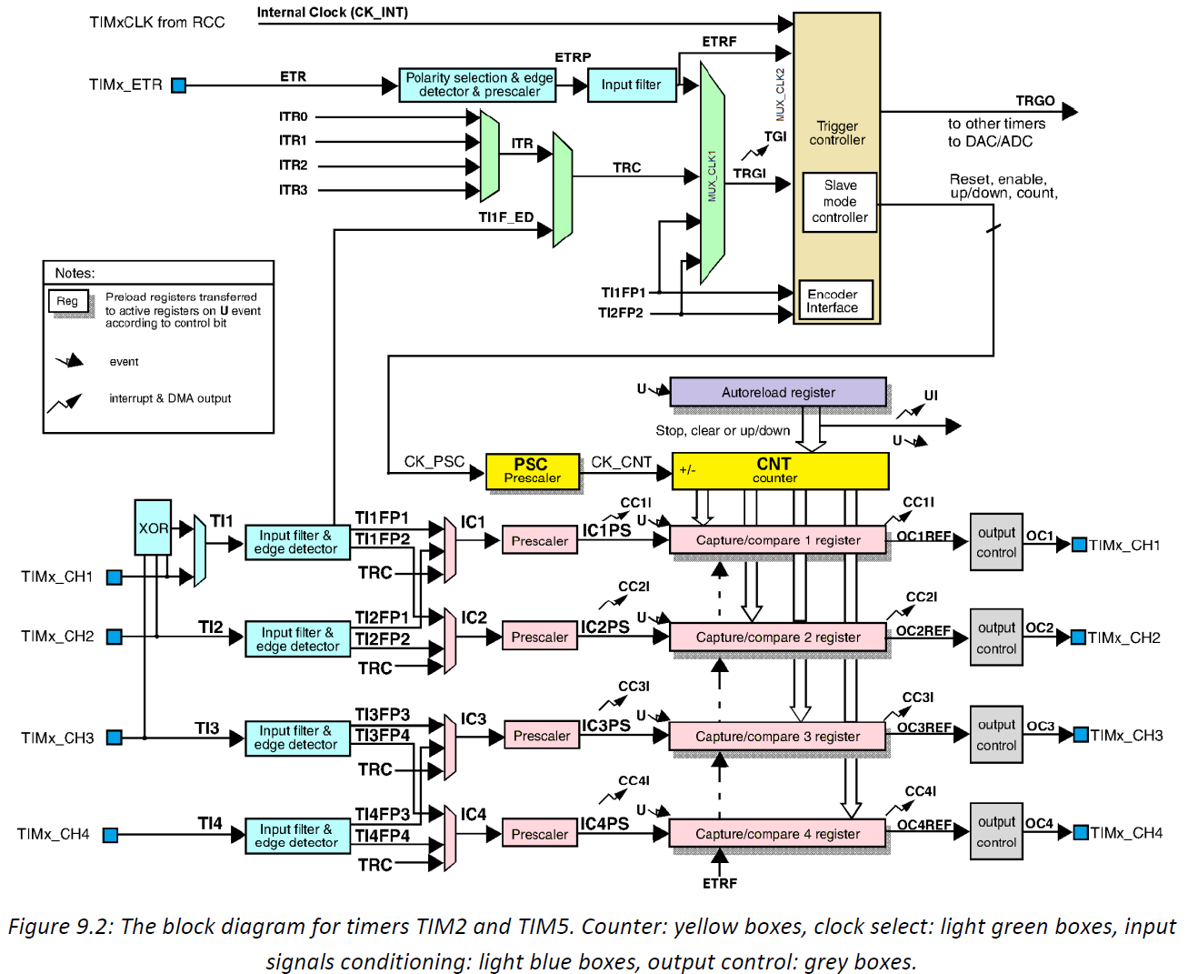
The counter advances on transitions of the clock signal CK_PSC.
This clock signal comes through a set of modules (light blue boxes and light green multiplexors) at the top of Fig. 9.2.
Several signals are offered to become the source of the clock signal, and multiplexors select one of them as the ‘CK_PSC’.
The user can configure multiplexors to pass signals connected to pins marked TIMx_CH1 to TIMx_CH4 or TIMx_ETR.
Alternatively, multiplexors can be configured to pass internally generated signals ITR0 to ITR3
or even internal clock signal CK_INT as a clock CK_PSC.
The counter can also be fed by some internally derived signals like TI1FP1, TI2FP2, and then some.
Details are given in reference manual RM0090, chapter 18.
Due to the availability of pins at the STM32F4-Discovery board and the limitations imposed by the BaseBoard
we will use pin 15, port A, and designate it as a source of signal TIM2_ETR,
which will in turn be routed through multiplexors to become the clock signal CK_PSC.
This pin is available at the connector K406 at the edge of the BaseBoard.
The timer block houses additional sub-blocks, which will not be used in this experiment on counting.
These blocks include prescaler modules, capture and compare modules, output modules and reload logic;
this will be used in subsequent experiments.

 浙公网安备 33010602011771号