SWD and JTAG selection mechanism
SWD and JTAG selection mechanism
SWJ-DP enables either an SWD or JTAG protocol to be used on the debug port.
To do this, it implements a watcher circuit that detects a specific 16-bit selection sequence on the SWDIOTMS pin:
-
A 16-bit sequence is used to switch from JTAG to SWD operation
-
Another 16-bit sequence is used to switch from SWD to JTAG.
The switcher defaults to JTAG operation on power-on reset,
therefore the JTAG protocol can be used from reset without sending a selection sequence.
Switching from one protocol to the other can only occur when the selected interface is in its reset state.
JTAG must be in its Test-Logic-Reset (TLR) state and SWD must be in line-reset.
The SWJ-DP contains a mode status output, JTAGNSW,
that is HIGH when the SWJ-DP is in JTAG mode and LOW when in SWD mode. This signal can be used to:
-
disable other TAP controllers when the SWJ-DP is in SWD mode, for example by disabling TCK or forcing TMS HIGH
-
multiplex the Serial Wire output, TRACESWO, on to another pin such as TDO when in SWD mode.
Another status output, JTAGTOP, indicates the state of the JTAG-DP TAP controller. These states are:
-
Test-Logic-Reset
-
Run-Test/Idle
-
Select-DR-Scan
-
Select-IR-Scan.
This signal can be used with JTAGNSW to control multiplexers so that,
for example, TDO and TDI can be reused as General Purpose Input/Output (GPIO) signals when the device is in SWD mode.
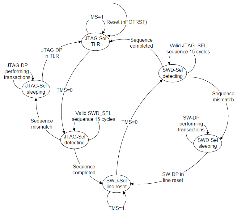
The watcher block puts itself to sleep when it has finished tracking a specific sequence and only wakes up again
when it detects the next reset condition.
Figure 2.3 is a simplified state diagram that shows how the watcher transitions between sleeping, detecting, and selection states.
Figure 2.3. SWD and JTAG select state diagram
SWJ-DP switching sequences
The SWJ-DP switching sequences are described in:
-
JTAG to SWD switching
-
SWD to JTAG switching.
JTAG to SWD switching
To switch SWJ-DP from JTAG to SWD operation:
-
Send more than 50 SWCLKTCK cycles with SWDIOTMS=1.
This ensures that both SWD and JTAG are in their reset states -
Send the 16-bit JTAG-to-SWD select sequence on SWDIOTMS
-
Send more than 50 SWCLKTCK cycles with SWDIOTMS=1.
This ensures that if SWJ-DP was already in SWD mode,
before sending the select sequence, the SWD goes to line reset. -
Perform a READID to validate that SWJ-DP has switched to SWD operation.
The 16-bit JTAG-to-SWD select sequence is defined to be 0b0111100111100111, MSB first.
This can be represented as 16'h79E7 if transmitted MSB first or 16'hE79E if transmitted LSB first.
This sequence has been chosen to ensure that the SWJ-DP switches to using SWD
whether it was previously expecting JTAG or SWD.
As long as the 50SWDIOTMS=1 sequence is sent first,
the JTAG-to-SWD select sequence is benign to SW-DP,
and is also benign to SWD and JTAG protocols used in the SWJ-DP,
and any other TAP controllers that might be connected to SWDIOTMS.
SWD to JTAG switching
To switch SWJ-DP from SWD to JTAG operation:
-
Send more than 50 SWCLKTCK cycles with SWDIOTMS=1.
This ensures that both SWD and JTAG are in their reset states. -
Send the 16-bit SWD-to-JTAG select sequence on SWDIOTMS.
-
Send at least five SWCLKTCK cycles with SWDIOTMS=1.
This ensures that if SWJ-DP was already in JTAG mode
before sending the select sequence, it goes into the TLR state. -
Set the JTAG-DP IR to READID and shift out the DR to read the ID.
The 16-bit JTAG-to-SWD select sequence is defined to be 0b0011110011100111, MSB first.
This can be represented as 16'h3CE7 if transmitted MSB first or 16'hE73C if transmitted LSB first.
This sequence has been chosen to ensure that the SWJ-DP switches to using JTAG
whether it was previously expecting JTAG or SWD.
If theSWDIOTMS=1 sequence is sent first, the SWD-to-JTAG select sequence is benign to SW-DP,
and is also benign to SWD and JTAG protocols used in the SWJ-DP,
and any other TAP controllers that might be connected to SWDIOTMS.
Restriction on switching
It is recommended that when a system is powered up, a debug connection is made, and the mode is selected,
either SWD or JTAG, that the system remains in this mode throughout the debug session.
Switching between modes must not be attempted while any component of the DAP is active.
If you attempt to switch between modes while any component of the DAP is active,
there can be unpredictable results.
A power-on reset cycle might be required to reset the DAP before switching can be retried.

 浙公网安备 33010602011771号