A CANBus Tiny Network without Transceiver ICs : STM32F4 Discovery
Sometimes you have a CAN equipped processor on a low cost board but it has no CAN transceiver chips.
Here is a method that can be used to create a small experimental network with such a board.
There will be no noise immunity and you might have to lower the speed….
but many experimenters have made this work satisfactorily.
Use a signal diode similar to 1N914 or 1N4148.
Power supply diodes usually do not have a fast enough recovery time for CAN to function.
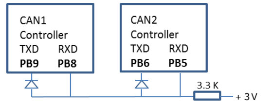
Modifying the STM32F4 Discovery:
In order to connect the two CAN controllers together, you must add two signal diodes (1N914, 1N4148 or similar)
and one 3.3 KΩ resistor as shown on this schematic.
The connections are easily accessible.
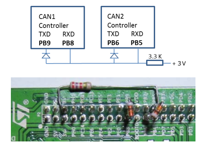
1. Add the three parts as shown on the schematic and in the photo.
2. Connect the resistor to the 3 volt supply as shown.
3. Add a jumper wire (not shown) from PB5 to PB8.
4. Note: I used a 2.7KΩ resistor and it seems to work well.
5. I soldered the components to the board.
6. Note: you will need to open the resistor for a step later.
You cannot connect this to a real CAN network as the voltages are wrong and it is not differential.
It is suitable for small experiments.
TIP: To view CAN frames on an oscilloscope: connect to the low side of the resistor. This will give a clean waveform.

 浙公网安备 33010602011771号