PWM DAC Low Pass Filtering
【TI博客大赛】【原创】LM3S811之基于PWM的DAC
http://bbs.ednchina.com/BLOG_ARTICLE_3005301.HTM
http://www.fpga4fun.com/PWM_DAC_3.html
One-bit DAC
Take one pin of an FPGA, connect a speaker and listen to an MP3? Easy.
Here, we'll use a PC to decode an MP3, and then send the decoded data to an FPGA that is configured as a one-bit DAC.

- 1. A speaker is connected directly to the FPGA. Since the speaker is mostly inductive, we control the current inside the speaker. That works, but is only recommended with high-impedance input speakers (or earphones).
- 2. An RC filter is used, then comes a speaker or amplified-speaker. That works only if the speaker has a high-enough input impedance so that it doesn't disturb the RC filter.
- 3. An RC filter is followed by an op-amp. That's the way to use to get the best music quality.
That's it! Listen to your favorite MP3 through an FPGA.
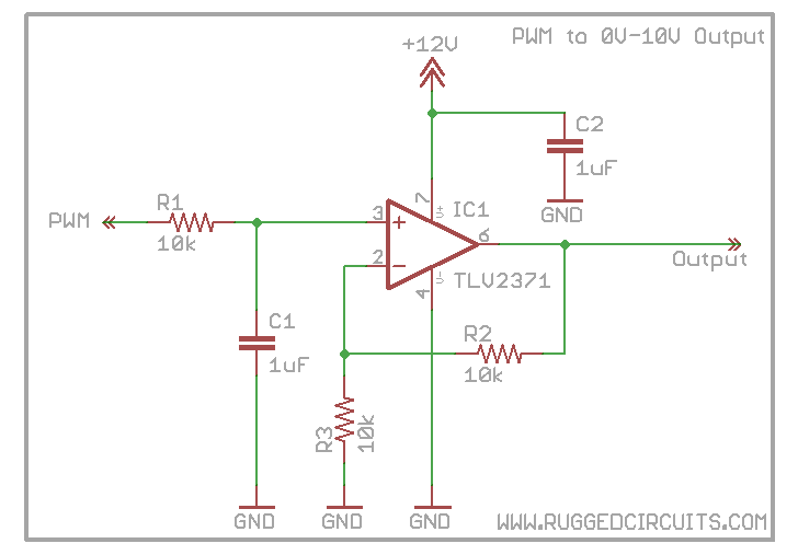
T5 dimming using 0-10V
http://forum.arduino.cc/index.php?topic=21889.0
An op-amp is capable of sourcing and sinking so it will work as a "buffer" as you require. I think you want something like this:
how to generate an analog output from a in-built pwm of Atmega 32AVR microcontrloller?
Please help me at how to generate a variable analog signal(0-5V) from a in-built AVR microcontroller's PWM(0-5V). I am doing a project on I-V data logger.I am using a MOSFET as variable load & want to drive the gate voltage(Vgs) of MOSFET by a variable voltage which comes from pwm of microcontroller. I would be very happy if somebody come up with answer. Thanks in advance.
Nagu Bhanoth
you need a resistor, a capacitor and an opamp.
opamp is not really necessary when you are driving a mosfet, but will make life a bit easier.
just be aware, that this dac will be quite noisy or/and slow. The bigger cap/resistor values, quiter and slower the output.
another thing to be aware is that you better use 16bit pwm, as 8 bit pwm will give you only 256 discrete values - that could be enough or too coarse, depends on your application, of course.
just google "PWM DAC" for more info and calculations.
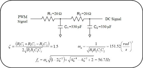
one more thing - you could put several resistor/capacitor stages in series to improve on the noise side:
Create a Low-Pass RC filter that will filter out the frequency of your PWM. The cutoff frequency should be at least 10 times lower than the frequency of your PWM. A lower cutoff frequency will reduce the voltage ripple in the output signal.
Cutoff frequency is determined by:
f = 1/(2πRC)
Further reading:
http://provideyourown.com/2011/analogwrite-convert-pwm-to-voltage/
Arduino’s AnalogWrite – Converting PWM to a Voltage
http://provideyourown.com/2011/analogwrite-convert-pwm-to-voltage/

PWM Primer
Pulse width modulation (or PWM as it is most commonly known), is a way of encoding a voltage onto a fixed frequency carrier wave. Commonly used for radio controlled devices, it is similar to FM (frequency modulation) or AM (amplitude modulation) in what it accomplishes. Each type of modulation scheme has its own advantages and disadvantages. AM modulation was the first type of modulation used for radio transmissions. It is the most simple modulation scheme to implement, requiring only a single transistor or vacuum tube amplifier as was done in the early days of radio. However, it suffers from excessive noise and therefore, FM modulation was invented. In this modulation technique, the voltage signal is no longer related to the strength of the signal. That is why FM radio has superior noise and fidelity qualities over AM radio, though it is not as simple to implement in circuitry.
With the need for digital communication, a new modulation technique was invented – PWM. This technique shares the same noise immunity as FM, to which it is very similar. The biggest difference is the simplicity and digital nature of the modulation. Instead of varying the modulation frequency with voltage, an output is merely switched on and off at a fixed frequency. The percentage of the on-time is in proportion to the signal voltage. To see better what this means, let’s examine what a PWM signal looks like for various levels. In the following image, the duty cycle is the output value from the PWM pin of an Arduino divided by 255:

For the Arduino, you write a value from 0 to 255 on a PWM pin, and the Arduino library will cause the pin to output a PWM signal whose on time is in proportion to the value written.
When it comes time for us to actually write an output voltage, the 0-255 value lacks meaning. What we want is many cases is a voltage. For our purposes, we will assume the Arduino is running at Vcc = 5 volts. In that case, a value of 255 will also be 5 volts. We can then easily convert the desired voltage to the digital value needed using simple division. We first divide the voltage we want by the 5 volts maximum. That gives us the percentage of our PWM signal. We then multiply this percentage by 255 to give us our pin value. Here is the formula:
Pin Value (0-255) = 255 * (AnalogVolts / 5);
Low Pass Filtering
Now that you understand how PWM works and can even change the frequency, it is time to take a look at how to implement a simple low pass filter. This simple piece of circuitry will convert your PWM output into a voltage corresponding to the percentage of the PWM waveform. You will then have a complete D-A converter for your Arduino or other microcontroller.

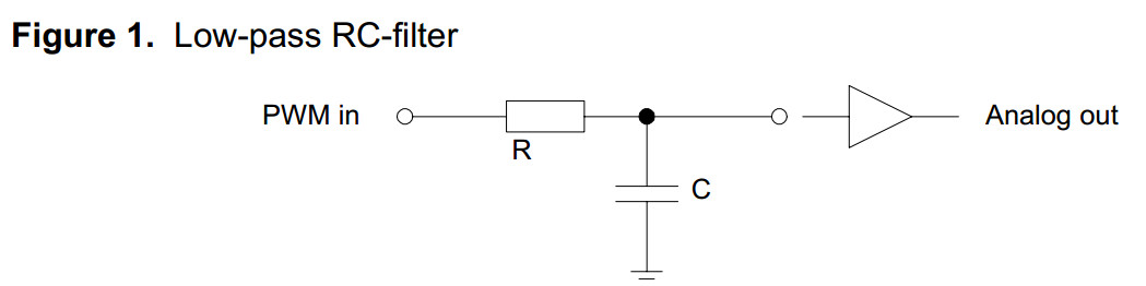
RC Low Pass Filter
If we examine the circuit on the left, when a voltage is applied to the input of R, the capacitor C will begin to charge. When it is charged, it will cease to conduct current and the voltage at the output of this circuit will match the input (assuming a high impedance load). If you remember that capacitors block DC currents, but pass AC currents, you can see that any DC voltage input will also be output, but high frequency AC voltages will be shorted to ground. For anything in between, i.e. lower frequency AC voltages, they will be filtered according to the R/C time constant formed by the resistor-capacitor network.
While this circuit is very simple, choosing the appropriate values for R & C encompass some design decisions – namely, how much ripple can we tolerate and how fast does the filter need to respond? These two parameters are mutually exclusive. In most filters, we would like to have the perfect filter – one that passes all frequencies below the cutoff frequency, with no voltage ripple. While no such ideal filter exists, we can achieve close to it by using a multiple pole filter. Such a filter would incorporate many components in a ladder configuration. While such a filter has wonderful performance characteristics, its complexity and cost is unnecessary for simple D-A conversion.
In such cases, we only need a simple single pole filter as shown above. We can achieve a reasonable voltage ripple for a single price – a low cutoff frequency. A low cutoff frequency has two ramifications. First, it limits the speed by which we can vary our output voltage. Second, there is a response delay when changing the voltage until the steady-state voltage is reached. For many of the more common applications, this trade-off is perfectly acceptable. Let’s now look at an example.
First, let’s choose our maximum ripple voltage. When we filter this high frequency PWM signal, a small component of it will always make it through the filter. That happens because our capacitor is too small to filter it out entirely. We could choose a very large capacitor /resistor combination that would get a very high proportion of it, but then it would take a long time to reach the proper output voltage as the capacitor charges. That would greatly limit how fast our signal can change and be seen at the output. Therefore, we need to choose a reasonable value for the ripple voltage. A popular application would be to change the voltage of a MOSFET. Since MOSFETs are voltage controlled devices, we can easily drive them with our microcontroller with PWM and a low-pass filter. Any ripple voltage present at the input would also be present at the output. For this example, assume the MOSFET will be driving a non-critical load such as a high power LED. In this instance, we merely need to stay within reasonable limits so the peak current in the LED will not be exceeded. In this case a 0.1 volt ripple would be more than adequate.
Next we choose a capacitor value. While it would seem the next step would be choosing a cutoff frequency (and it normally would be), there are additional considerations such as output load and capacitor cost. If we were only driving the gate of a MOSFET, there would be no output load to speak of. In such case, we could choose a cheap ceramic cap such as 0.1uF and then choose the resistor we need to achieve the cutoff frequency desired. If, on the other hand, we need some current from our output, then we will need a smaller resistor and a correspondingly larger capacitor. For a recent circuit, I found I needed a 2.2uF capacitor to prevent my modest load from altering the output voltage too significantly. Designing this circuit for non-trivial loads is beyond the scope of this article. If you find yourself in such a need, the best approach would be to start with at least a 1uF capacitor and then test how your output voltage changes with load. Increase your capacitor until the load has a low enough effect to be acceptable. Another way to look at this circuit would be to think of it as a poorly regulated power supply. It only meant to convert digital signals to an output voltage; not to drive a load as well. Buffer the output with an op-amp or a FET first. Then drive your load.
For our example, let’s choose a capacitor value of 1.0uF. For driving a MOSFET, you can use something even smaller, but this size will let us have a small load. Next, we need to choose a cutoff frequency or response time. These two parameters are related but not the same. For simple things like driving LEDs, we are more concerned with a response time. Our response time can be pretty generous. Let’s choose a settling time (to reach 90% of the final value) of 0.1 seconds, which would require a resistor of 15K ohms.
You may be wondering how to calculate these values, or others of your own. Rather than delve into a lot of equations, I have found something better. This excellent online calculator does all the hard math for you, calculating cutoff frequency, response times, voltage ripple and other values. It even draws a transient analysis graph for you – displaying your ripple and how the voltage ramps up over time. Here is the output graph for this example:

RC Low Pass Filter Time Response http://sim.okawa-denshi.jp/en/PWMtool.php
http://sim.okawa-denshi.jp/en/CRtool.php
AVR131: Using the AVR’s High-speed PWM
http://www.atmel.com/Images/doc2542.pdf
Theory of Operation
PWM combined with an analog filter can be used to generate analog output signals, i.e. a digital to analog converter (DAC).
A digital pulse train with a constant period (fixed base frequency) is used as a basis.
To generate different analog levels, the duty cycle and thereby the pulse width of the digital signal is changed.
If a high analog level is needed, the pulse width is increased and vice versa.
Averaging the digital signal over one period (using an analog low-pass filter) generates the analog signal.
A duty cycle of 50% gives an analog signal with half the supply voltage, while 75% duty cycle gives an analog signal with 75% supply voltage.
Examples on filtered output signals are shown at the end of this document.
The analog low-pass filter could be a simple passive RC-filter for instance.
The filter removes the high PWM base frequency and lets through the analog signal.
The filter crossover frequency must be chosen high enough to not alter the analog signal of interest.
At the same time it must be as low as possible to minimize the ripple from the PWM base frequency.
If the analog signal is fed to a low-impedance input, a buffer amplifier should be connected between the filter output and the load.
This will prevent the load from discharging the capacitor and creating ripple voltages.

The following scope pictures are examples of sine wave signals generated by the ATtiny26 PWM.
The scope snap-shots show the output on the OC1A pin, which is the digital pulse modulated signal, and the filtered/shaped PWM signal.
A simple RC filter is used to shape the PWM signal to a sine wave – an analog signal where the amplitude is given by the duty cycle of the PWM output.
The RC filter used has an R = 10 kΩ and a C = 100 nF, resulting in a filter crossover frequency of 1 kHz,
which will let the low frequency sine wave pass while filtering out the high frequency PWM base.


http://www.allaboutcircuits.com/worksheets/dac.html
Digital-to-Analog conversion
Question 1:
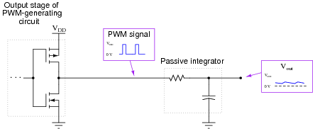
If a pulse-width modulated (PWM) signal is sent to a passive integrator circuit from a circuit capable of both sourcing and sinking current (as is the case with the dual-MOSFET output stage), the output will be a DC voltage (with some ripple):
Follow-up question #1: why is it important that the circuit generating the PWM signal for the integrator be able to both source and sink current?
Follow-up question #2: what would have to be done to reduce the ripple voltage at the integrator's output?
Although it should not be difficult for students to discern the relationship between duty cycle and DC output voltage, the application of this relationship to data communication might be difficult for some students to grasp, especially on their own. Further elaboration on your part may be necessary.
An excellent example of this principle applied is the generation of an analog voltage by a 1-bit digital circuit. This technique is useful in microcontroller systems where output ports may be scarce, provided that ripple voltage (or slow response) is not a problem.

 浙公网安备 33010602011771号