
【自学嵌入式:stm32单片机】按键控制LED
按键控制LED
接线图
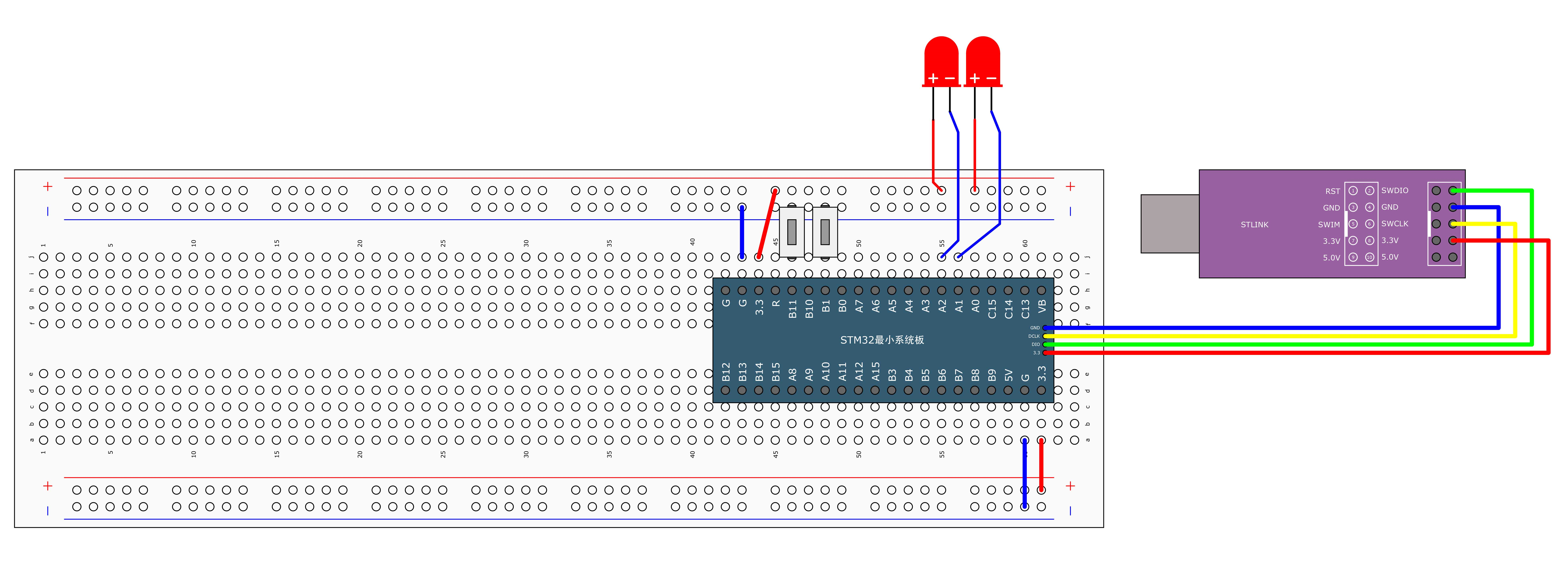
按键连着吃力,可以考虑杜邦线连接(虽然看着不好看就是了)
面板正负极标志和视频里是反向的,要注意接线
使用标准库实现
已开源到仓库:https://gitee.com/qin-ruiqian/jiangkeda-stm32
Key.h
#ifndef __KEY_H
#define __KEY_H

void Key_Init(void); //初始化按键
uint8_t Key_GetNum(void); //读取按键值

#endif
Key.c
#include "stm32f10x.h"                  // Device header
#include "Delay.h"

//初始化按键
void Key_Init(void)
{
	//打开APB2总线GPIOB外设端口,并开启时钟
	RCC_APB2PeriphClockCmd(RCC_APB2Periph_GPIOB, ENABLE);
	GPIO_InitTypeDef GPIO_InitStructure;
	GPIO_InitStructure.GPIO_Mode = GPIO_Mode_IPU; //读取按键,选择上拉输入
	GPIO_InitStructure.GPIO_Pin = GPIO_Pin_1 | GPIO_Pin_11; //选的是PB1和PB11
	GPIO_InitStructure.GPIO_Speed = GPIO_Speed_50MHz;
	GPIO_Init(GPIOB, &GPIO_InitStructure);
}

//读取按键值
uint8_t Key_GetNum(void)
{
	uint8_t KeyNum = 0;
	if(GPIO_ReadInputDataBit(GPIOB, GPIO_Pin_1) == 0) //读取PB1口的电平
	{
		Delay_ms(20); //消抖
		while(GPIO_ReadInputDataBit(GPIOB, GPIO_Pin_1) == 0); //直到按键松手
		Delay_ms(20); //消抖
		KeyNum = 1;
	}
	if(GPIO_ReadInputDataBit(GPIOB, GPIO_Pin_11) == 0) //读取PB11口的电平
	{
		Delay_ms(20); //消抖
		while(GPIO_ReadInputDataBit(GPIOB, GPIO_Pin_11) == 0); //直到按键松手
		Delay_ms(20); //消抖
		KeyNum = 2;
	}
	return KeyNum;
}
LED.h
#ifndef __LED_H
#define __LED_H

void LED_Init(void); //初始化LED灯的IO口
void LED1_ON(void); //打开LED1
void LED1_OFF(void); //关闭LED1
void LED2_ON(void); //打开LED2
void LED2_OFF(void); //关闭LED2
void LED1_Turn(void); //LED1电平翻转
void LED2_Turn(void); //LED2电平翻转

#endif
LED.c
#include "stm32f10x.h"                  // Device header

//初始化LED
void LED_Init(void)
{
	//打开APB2总线的GPIOA外设并开启时钟
	RCC_APB2PeriphClockCmd(RCC_APB2Periph_GPIOA, ENABLE);
	GPIO_InitTypeDef GPIO_InitStructure;
	GPIO_InitStructure.GPIO_Mode = GPIO_Mode_Out_PP; //推挽输出
	GPIO_InitStructure.GPIO_Pin = GPIO_Pin_1 | GPIO_Pin_2; //A1口,A2口打开
	GPIO_InitStructure.GPIO_Speed = GPIO_Speed_50MHz;
	GPIO_Init(GPIOA, &GPIO_InitStructure);
	//让GPIO默认高电平,让LED一开始是熄灭状态
	GPIO_SetBits(GPIOA, GPIO_Pin_1 | GPIO_Pin_2);
}

//点亮LED1
void LED1_ON(void)
{
	GPIO_ResetBits(GPIOA, GPIO_Pin_1); //PA1口设低电平,点亮LED
}

//熄灭LED1
void LED1_OFF(void)
{
	GPIO_SetBits(GPIOA, GPIO_Pin_1); //PA1口设置高电平,LED熄灭,其余同理
}

//取反LED1的状态,端口电平翻转
void LED1_Turn(void)
{
	//PA1置1
	if(GPIO_ReadInputDataBit(GPIOA, GPIO_Pin_1) == 0)
	{
		GPIO_SetBits(GPIOA, GPIO_Pin_1);
	}
	else //PA1置0
	{
		GPIO_ResetBits(GPIOA, GPIO_Pin_1);
	}
}

//取反LED2的状态,端口电平翻转
void LED2_Turn(void)
{
	//PA1置1
	if(GPIO_ReadInputDataBit(GPIOA, GPIO_Pin_2) == 0)
	{
		GPIO_SetBits(GPIOA, GPIO_Pin_2);
	}
	else //PA1置0
	{
		GPIO_ResetBits(GPIOA, GPIO_Pin_2);
	}
}

//点亮LED2
void LED2_ON(void)
{
	GPIO_ResetBits(GPIOA, GPIO_Pin_2); //PA1口设低电平,点亮LED
}

//熄灭LED2
void LED2_OFF(void)
{
	GPIO_SetBits(GPIOA, GPIO_Pin_2); //PA1口设置高电平,LED熄灭,其余同理
}
main.c
#include "stm32f10x.h"                  // Device header
#include "Delay.h"
#include "LED.h"
#include "Key.h"

uint8_t KeyNum; //键码值

int main(void)
{
	LED_Init(); //初始化LED的IO口
	Key_Init(); //初始化按键
	while(1)
	{
		KeyNum = Key_GetNum();
		switch(KeyNum)
		{
			case 1:
				LED1_Turn();
				break;
			case 2:
				LED2_Turn();
				break;
		}
	}
}
使用HAL库实现
代码太多了,HAL库实现代码存到了这个开源仓库中:https://gitee.com/qin-ruiqian/jiangkeda-stm32-hal
IDE设置
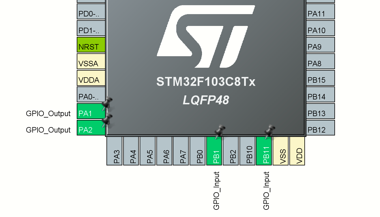
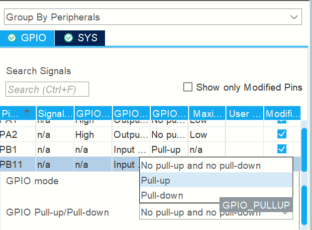
先把PB1和PB11设置为GPIO_INPUT,然后设置上拉模式
设置PA1和PA2为GPIO_OUTPUT,然后设置推挽输出
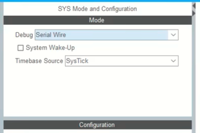
别忘了把调试接口写上去
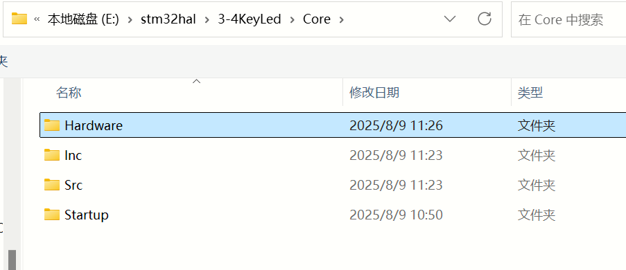
建立Hardware文件夹,把要实现的LED和按键代码写在独立的头文件和源文件中,由于自动生成的代码已经初始化了GPIO,所以Hardware下的源文件直接实现相关逻辑就行
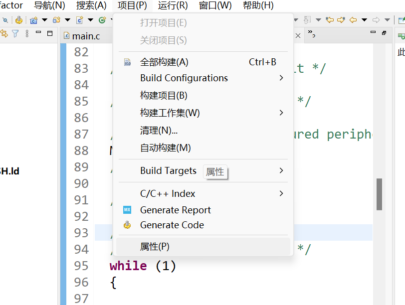
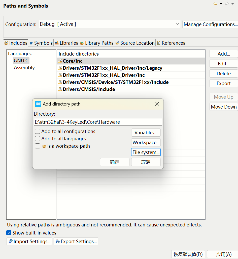
在项目属性里面把刚才添加的Hardware文件夹添加include路径中,让编译器明白我的LED和按键的头文件和源文件都在哪
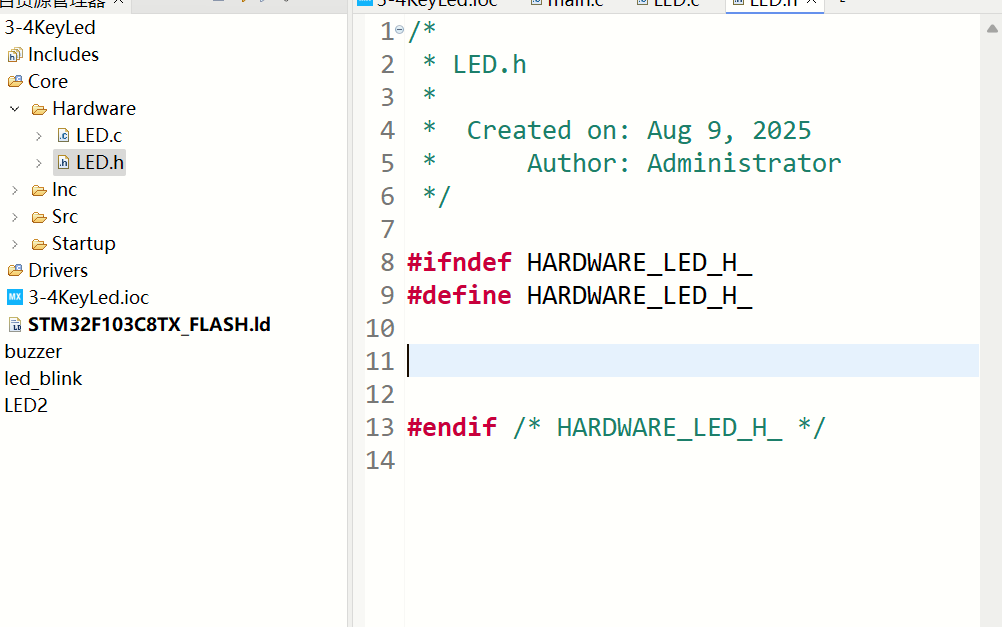
然后建立相应的头文件和源文件
Key.h
/*
 * Key.h
 *
 *  Created on: Aug 9, 2025
 *      Author: Administrator
 */

#ifndef HARDWARE_KEY_H_
#define HARDWARE_KEY_H_

uint8_t Key_GetNum(void); //读按键值

#endif /* HARDWARE_KEY_H_ */
Key.c
/*
 * Key.c
 *
 *  Created on: Aug 9, 2025
 *      Author: Administrator
 */
#include "stm32f1xx_hal.h"

//读取按键值
uint8_t Key_GetNum(void)
{
	uint8_t KeyNum = 0;
	if(HAL_GPIO_ReadPin(GPIOB, GPIO_PIN_1) == 0)
	{
		HAL_Delay(20); //消抖
		while(HAL_GPIO_ReadPin(GPIOB, GPIO_PIN_1) == 0); //直到按键松手
		HAL_Delay(20); //消抖
		KeyNum = 1;
	}
	if(HAL_GPIO_ReadPin(GPIOB, GPIO_PIN_11) == 0)
	{
		HAL_Delay(20); //消抖
		while(HAL_GPIO_ReadPin(GPIOB, GPIO_PIN_11) == 0); //直到按键松手
		HAL_Delay(20); //消抖
		KeyNum = 2;
	}
	return KeyNum;
}
LED.h
/*
 * LED.h
 *
 *  Created on: Aug 9, 2025
 *      Author: Administrator
 */

#ifndef HARDWARE_LED_H_
#define HARDWARE_LED_H_

void LED1_Turn(void); //切换LED1状态
void LED2_Turn(void); //切换LED2状态

#endif /* HARDWARE_LED_H_ */
LED.c
/*
 * LED.c
 *
 *  Created on: Aug 9, 2025
 *      Author: Administrator
 */

#include "stm32f1xx_hal.h"

//PA1口LED灯开关取反,低电平亮
void LED1_Turn(void)
{
	//如果是低电平,就切换高电平
	//如果是高电平,就切换低电平
	if(HAL_GPIO_ReadPin(GPIOA, GPIO_PIN_1) == 0)
	{
		HAL_GPIO_WritePin(GPIOA, GPIO_PIN_1, GPIO_PIN_SET);
	}
	else
	{
		HAL_GPIO_WritePin(GPIOA, GPIO_PIN_1, GPIO_PIN_RESET);
	}
}

//LED2同理
void LED2_Turn(void)
{
	//如果是低电平,就切换高电平
	//如果是高电平,就切换低电平
	if(HAL_GPIO_ReadPin(GPIOA, GPIO_PIN_2) == 0)
	{
		HAL_GPIO_WritePin(GPIOA, GPIO_PIN_2, GPIO_PIN_SET);
	}
	else
	{
		HAL_GPIO_WritePin(GPIOA, GPIO_PIN_2, GPIO_PIN_RESET);
	}
}
main.c
根据自动生成的注释,将代码写在对应位置,要不然编译器不识别
/* USER CODE BEGIN Header */
/**
  ******************************************************************************
  * @file           : main.c
  * @brief          : Main program body
  ******************************************************************************
  * @attention
  *
  * Copyright (c) 2025 STMicroelectronics.
  * All rights reserved.
  *
  * This software is licensed under terms that can be found in the LICENSE file
  * in the root directory of this software component.
  * If no LICENSE file comes with this software, it is provided AS-IS.
  *
  ******************************************************************************
  */
/* USER CODE END Header */
/* Includes ------------------------------------------------------------------*/
#include "main.h"

/* Private includes ----------------------------------------------------------*/
/* USER CODE BEGIN Includes */
#include "Key.h"
#include "LED.h"
/* USER CODE END Includes */

/* Private typedef -----------------------------------------------------------*/
/* USER CODE BEGIN PTD */

/* USER CODE END PTD */

/* Private define ------------------------------------------------------------*/
/* USER CODE BEGIN PD */

/* USER CODE END PD */

/* Private macro -------------------------------------------------------------*/
/* USER CODE BEGIN PM */

/* USER CODE END PM */

/* Private variables ---------------------------------------------------------*/

/* USER CODE BEGIN PV */
uint8_t KeyNum; //键码值
/* USER CODE END PV */

/* Private function prototypes -----------------------------------------------*/
void SystemClock_Config(void);
static void MX_GPIO_Init(void);
/* USER CODE BEGIN PFP */

/* USER CODE END PFP */

/* Private user code ---------------------------------------------------------*/
/* USER CODE BEGIN 0 */

/* USER CODE END 0 */

/**
  * @brief  The application entry point.
  * @retval int
  */
int main(void)
{

  /* USER CODE BEGIN 1 */

  /* USER CODE END 1 */

  /* MCU Configuration--------------------------------------------------------*/

  /* Reset of all peripherals, Initializes the Flash interface and the Systick. */
  HAL_Init();

  /* USER CODE BEGIN Init */

  /* USER CODE END Init */

  /* Configure the system clock */
  SystemClock_Config();

  /* USER CODE BEGIN SysInit */

  /* USER CODE END SysInit */

  /* Initialize all configured peripherals */
  MX_GPIO_Init();
  /* USER CODE BEGIN 2 */

  /* USER CODE END 2 */

  /* Infinite loop */
  /* USER CODE BEGIN WHILE */
  while (1)
  {
	  KeyNum = Key_GetNum();
	  switch(KeyNum)
	  {
	  	  case 1:
	  		  LED1_Turn();
	  		  break;
	  	  case 2:
	  		  LED2_Turn();
	  		  break;
	  }
    /* USER CODE END WHILE */

    /* USER CODE BEGIN 3 */
  }
  /* USER CODE END 3 */
}

/**
  * @brief System Clock Configuration
  * @retval None
  */
void SystemClock_Config(void)
{
  RCC_OscInitTypeDef RCC_OscInitStruct = {0};
  RCC_ClkInitTypeDef RCC_ClkInitStruct = {0};

  /** Initializes the RCC Oscillators according to the specified parameters
  * in the RCC_OscInitTypeDef structure.
  */
  RCC_OscInitStruct.OscillatorType = RCC_OSCILLATORTYPE_HSI;
  RCC_OscInitStruct.HSIState = RCC_HSI_ON;
  RCC_OscInitStruct.HSICalibrationValue = RCC_HSICALIBRATION_DEFAULT;
  RCC_OscInitStruct.PLL.PLLState = RCC_PLL_NONE;
  if (HAL_RCC_OscConfig(&RCC_OscInitStruct) != HAL_OK)
  {
    Error_Handler();
  }

  /** Initializes the CPU, AHB and APB buses clocks
  */
  RCC_ClkInitStruct.ClockType = RCC_CLOCKTYPE_HCLK|RCC_CLOCKTYPE_SYSCLK
                              |RCC_CLOCKTYPE_PCLK1|RCC_CLOCKTYPE_PCLK2;
  RCC_ClkInitStruct.SYSCLKSource = RCC_SYSCLKSOURCE_HSI;
  RCC_ClkInitStruct.AHBCLKDivider = RCC_SYSCLK_DIV1;
  RCC_ClkInitStruct.APB1CLKDivider = RCC_HCLK_DIV1;
  RCC_ClkInitStruct.APB2CLKDivider = RCC_HCLK_DIV1;

  if (HAL_RCC_ClockConfig(&RCC_ClkInitStruct, FLASH_LATENCY_0) != HAL_OK)
  {
    Error_Handler();
  }
}

/**
  * @brief GPIO Initialization Function
  * @param None
  * @retval None
  */
static void MX_GPIO_Init(void)
{
  GPIO_InitTypeDef GPIO_InitStruct = {0};
  /* USER CODE BEGIN MX_GPIO_Init_1 */

  /* USER CODE END MX_GPIO_Init_1 */

  /* GPIO Ports Clock Enable */
  __HAL_RCC_GPIOA_CLK_ENABLE();
  __HAL_RCC_GPIOB_CLK_ENABLE();

  /*Configure GPIO pin Output Level */
  HAL_GPIO_WritePin(GPIOA, GPIO_PIN_1|GPIO_PIN_2, GPIO_PIN_SET);

  /*Configure GPIO pins : PA1 PA2 */
  GPIO_InitStruct.Pin = GPIO_PIN_1|GPIO_PIN_2;
  GPIO_InitStruct.Mode = GPIO_MODE_OUTPUT_PP;
  GPIO_InitStruct.Pull = GPIO_NOPULL;
  GPIO_InitStruct.Speed = GPIO_SPEED_FREQ_LOW;
  HAL_GPIO_Init(GPIOA, &GPIO_InitStruct);

  /*Configure GPIO pins : PB1 PB11 */
  GPIO_InitStruct.Pin = GPIO_PIN_1|GPIO_PIN_11;
  GPIO_InitStruct.Mode = GPIO_MODE_INPUT;
  GPIO_InitStruct.Pull = GPIO_PULLUP;
  HAL_GPIO_Init(GPIOB, &GPIO_InitStruct);

  /* USER CODE BEGIN MX_GPIO_Init_2 */

  /* USER CODE END MX_GPIO_Init_2 */
}

/* USER CODE BEGIN 4 */

/* USER CODE END 4 */

/**
  * @brief  This function is executed in case of error occurrence.
  * @retval None
  */
void Error_Handler(void)
{
  /* USER CODE BEGIN Error_Handler_Debug */
  /* User can add his own implementation to report the HAL error return state */
  __disable_irq();
  while (1)
  {
  }
  /* USER CODE END Error_Handler_Debug */
}

#ifdef  USE_FULL_ASSERT
/**
  * @brief  Reports the name of the source file and the source line number
  *         where the assert_param error has occurred.
  * @param  file: pointer to the source file name
  * @param  line: assert_param error line source number
  * @retval None
  */
void assert_failed(uint8_t *file, uint32_t line)
{
  /* USER CODE BEGIN 6 */
  /* User can add his own implementation to report the file name and line number,
     ex: printf("Wrong parameters value: file %s on line %d\r\n", file, line) */
  /* USER CODE END 6 */
}
#endif /* USE_FULL_ASSERT */

 浙公网安备 33010602011771号