
【自学嵌入式:STM32单片机】LED闪烁与LED流水灯
点亮LED
用标准库实现
接线如下
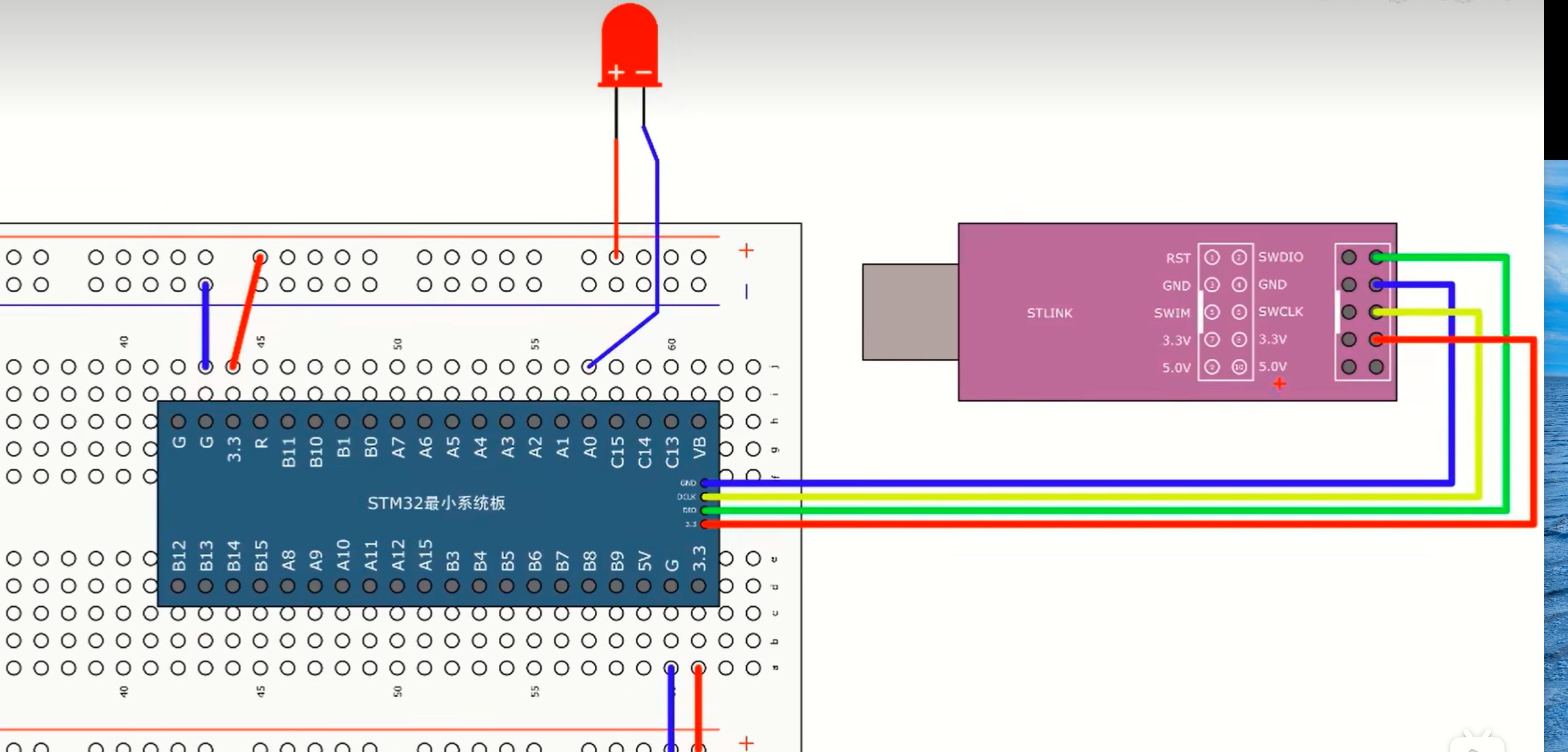
GPIO PA0口低电平点亮
#include "stm32f10x.h"                  // Device header

int main(void)
{
	//点亮PA0口的LED,需要RCC APB2外设 GIOPA
	//打开了APB2总线时钟
	RCC_APB2PeriphClockCmd(RCC_APB2Periph_GPIOA, ENABLE); //注意是RCC_APB2PeriphClockCmd,而不是RCC_APB2PeriphResetCmd
	GPIO_InitTypeDef GPIO_InitStruct; //GPIO外设参数结构体
	GPIO_InitStruct.GPIO_Mode = GPIO_Mode_Out_PP; //设置推挽输出
	GPIO_InitStruct.GPIO_Pin = GPIO_Pin_0; //0号引脚
	GPIO_InitStruct.GPIO_Speed = GPIO_Speed_50MHz; //端口配置50Mhz
	GPIO_Init(GPIOA, &GPIO_InitStruct); //初始化GPIO_Init
	GPIO_ResetBits(GPIOA, GPIO_Pin_0); //给GPIOA的0号引脚设置为低电平
	while(1)
	{

	}
}
此时LED灯亮,下面将GPIO口PA0口设置低电平,灯灭
#include "stm32f10x.h"                  // Device header

int main(void)
{
	//点亮PA0口的LED,需要RCC APB2外设 GIOPA
	//打开了APB2总线时钟
	RCC_APB2PeriphClockCmd(RCC_APB2Periph_GPIOA, ENABLE);
	GPIO_InitTypeDef GPIO_InitStruct; //GPIO外设参数结构体
	GPIO_InitStruct.GPIO_Mode = GPIO_Mode_Out_PP; //设置推挽输出
	GPIO_InitStruct.GPIO_Pin = GPIO_Pin_0; //0号引脚
	GPIO_InitStruct.GPIO_Speed = GPIO_Speed_50MHz; //端口配置50Mhz
	GPIO_Init(GPIOA, &GPIO_InitStruct); //初始化GPIO_Init
	GPIO_SetBits(GPIOA, GPIO_Pin_0); //给GPIOA的0号引脚设置为高电平
	while(1)
	{

	}
}
用GPIO_WriteBit来点灯
#include "stm32f10x.h"                  // Device header

int main(void)
{
	//点亮PA0口的LED,需要RCC APB2外设 GIOPA
	//打开了APB2总线时钟
	RCC_APB2PeriphClockCmd(RCC_APB2Periph_GPIOA, ENABLE);
	GPIO_InitTypeDef GPIO_InitStruct; //GPIO外设参数结构体
	GPIO_InitStruct.GPIO_Mode = GPIO_Mode_Out_PP; //设置推挽输出
	GPIO_InitStruct.GPIO_Pin = GPIO_Pin_0; //0号引脚
	GPIO_InitStruct.GPIO_Speed = GPIO_Speed_50MHz; //端口配置50Mhz
	GPIO_Init(GPIOA, &GPIO_InitStruct); //初始化GPIO_Init
	//GPIO_SetBits(GPIOA, GPIO_Pin_0); //给GPIOA的0号引脚设置为高电平
	GPIO_WriteBit(GPIOA, GPIO_Pin_0, Bit_RESET); //用WriteBit,最后一个参数Bit_SET置高电平,Bit_RESET置低电平
	while(1)
	{

	}
}
LED闪烁
用标准库实现
用江科大给的延时函数(用SysTick定时器来实现的延时)
500ms闪烁一次
#include "stm32f10x.h"                  // Device header
#include "Delay.h"

int main(void)
{
	//点亮PA0口的LED,需要RCC APB2外设 GIOPA
	//打开了APB2总线时钟
	RCC_APB2PeriphClockCmd(RCC_APB2Periph_GPIOA, ENABLE);
	GPIO_InitTypeDef GPIO_InitStruct; //GPIO外设参数结构体
	GPIO_InitStruct.GPIO_Mode = GPIO_Mode_Out_PP; //设置推挽输出
	GPIO_InitStruct.GPIO_Pin = GPIO_Pin_0; //0号引脚
	GPIO_InitStruct.GPIO_Speed = GPIO_Speed_50MHz; //端口配置50Mhz
	GPIO_Init(GPIOA, &GPIO_InitStruct); //初始化GPIO_Init
	while(1)
	{
		GPIO_WriteBit(GPIOA, GPIO_Pin_0, Bit_RESET); //点亮LED
		Delay_ms(500);
		GPIO_WriteBit(GPIOA, GPIO_Pin_0, Bit_SET); //熄灭LED
		Delay_ms(500);
	}
}
也可以用SetBits和ResetBits实现,如果想在WriteBit的第三个参数写1和0,需要强制类型转换为BitAction
此时是推挽输出,把LED短针接在负极,长针接在PA0,也能正常闪烁
现在把端口模式换成Out_OD开漏输出
#include "stm32f10x.h"                  // Device header
#include "Delay.h"

int main(void)
{
	//点亮PA0口的LED,需要RCC APB2外设 GIOPA
	//打开了APB2总线时钟
	RCC_APB2PeriphClockCmd(RCC_APB2Periph_GPIOA, ENABLE);
	GPIO_InitTypeDef GPIO_InitStruct; //GPIO外设参数结构体
	GPIO_InitStruct.GPIO_Mode = GPIO_Mode_Out_OD; //设置开漏输出
	GPIO_InitStruct.GPIO_Pin = GPIO_Pin_0; //0号引脚
	GPIO_InitStruct.GPIO_Speed = GPIO_Speed_50MHz; //端口配置50Mhz
	GPIO_Init(GPIOA, &GPIO_InitStruct); //初始化GPIO_Init
	while(1)
	{
		GPIO_WriteBit(GPIOA, GPIO_Pin_0, Bit_RESET); //点亮LED
		Delay_ms(500);
		GPIO_WriteBit(GPIOA, GPIO_Pin_0, Bit_SET); //熄灭LED
		Delay_ms(500);
	}
}
此时LED就不亮了,LED不亮,说明开漏输出的模式高电平是没有驱动能力的,再把线改回低电平驱动(长针接正极,短针接P0),此时LED正常闪烁,说明开漏模式的低电平是有驱动能力的
开漏输出高电平相当于高阻态,没有驱动能力,低电平有驱动能力
所以还改回推挽输出,一般用推挽模式就行了
#include "stm32f10x.h"                  // Device header
#include "Delay.h"

int main(void)
{
	//点亮PA0口的LED,需要RCC APB2外设 GIOPA
	//打开了APB2总线时钟
	RCC_APB2PeriphClockCmd(RCC_APB2Periph_GPIOA, ENABLE);
	GPIO_InitTypeDef GPIO_InitStruct; //GPIO外设参数结构体
	GPIO_InitStruct.GPIO_Mode = GPIO_Mode_Out_PP; //设置推挽输出
	GPIO_InitStruct.GPIO_Pin = GPIO_Pin_0; //0号引脚
	GPIO_InitStruct.GPIO_Speed = GPIO_Speed_50MHz; //端口配置50Mhz
	GPIO_Init(GPIOA, &GPIO_InitStruct); //初始化GPIO_Init
	while(1)
	{
		GPIO_WriteBit(GPIOA, GPIO_Pin_0, Bit_RESET); //点亮LED
		Delay_ms(500);
		GPIO_WriteBit(GPIOA, GPIO_Pin_0, Bit_SET); //熄灭LED
		Delay_ms(500);
	}
}
用HAL库实现
此处参考网上其他教程,江科大没讲HAL库,我自学
打开STM32CubeIDE,按下图设置PA0为推挽输出

此时按ctrl+s自动生成代码
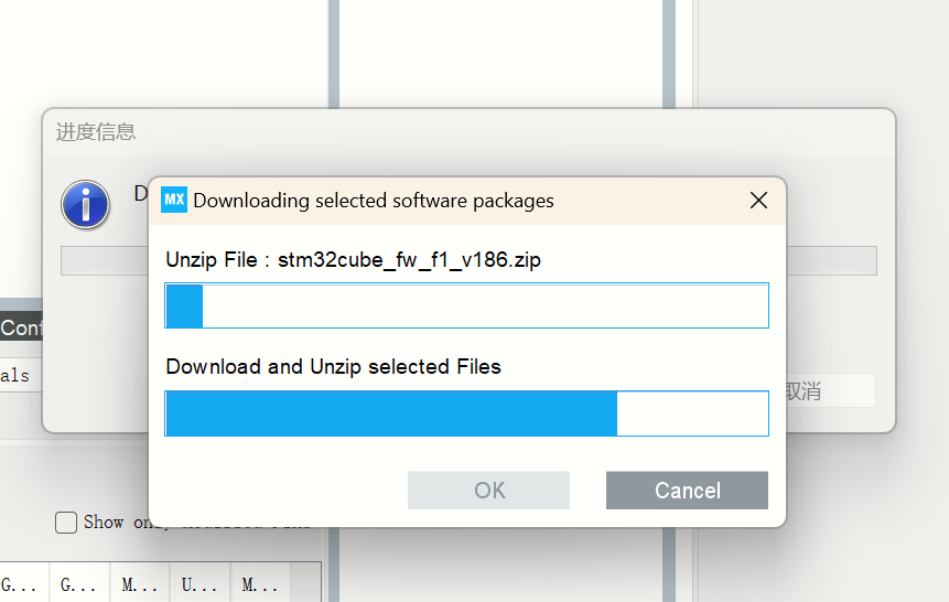
结果没生成,然后我配置了好久的网络,TM D才正常生成,我要问候ST公司一下,我要超市里的🐎

/* USER CODE BEGIN Header */
/**
  ******************************************************************************
  * @file           : main.c
  * @brief          : Main program body
  ******************************************************************************
  * @attention
  *
  * Copyright (c) 2025 STMicroelectronics.
  * All rights reserved.
  *
  * This software is licensed under terms that can be found in the LICENSE file
  * in the root directory of this software component.
  * If no LICENSE file comes with this software, it is provided AS-IS.
  *
  ******************************************************************************
  */
/* USER CODE END Header */
/* Includes ------------------------------------------------------------------*/
#include "main.h"
#include "gpio.h"

/* Private includes ----------------------------------------------------------*/
/* USER CODE BEGIN Includes */

/* USER CODE END Includes */

/* Private typedef -----------------------------------------------------------*/
/* USER CODE BEGIN PTD */

/* USER CODE END PTD */

/* Private define ------------------------------------------------------------*/
/* USER CODE BEGIN PD */

/* USER CODE END PD */
/* Private macro -------------------------------------------------------------*/
/* USER CODE BEGIN PM */

/* USER CODE END PM */

/* Private variables ---------------------------------------------------------*/

/* USER CODE BEGIN PV */

/* USER CODE END PV */

/* Private function prototypes -----------------------------------------------*/
void SystemClock_Config(void);
/* USER CODE BEGIN PFP */

/* USER CODE END PFP */

/* Private user code ---------------------------------------------------------*/
/* USER CODE BEGIN 0 */

/* USER CODE END 0 */

/**
  * @brief  The application entry point.
  * @retval int
  */
int main(void)
{

  /* USER CODE BEGIN 1 */

  /* USER CODE END 1 */

  /* MCU Configuration--------------------------------------------------------*/

  /* Reset of all peripherals, Initializes the Flash interface and the Systick. */
  HAL_Init();

  /* USER CODE BEGIN Init */

  /* USER CODE END Init */

  /* Configure the system clock */
  SystemClock_Config();

  /* USER CODE BEGIN SysInit */

  /* USER CODE END SysInit */

  /* Initialize all configured peripherals */
  MX_GPIO_Init();
  /* USER CODE BEGIN 2 */

  /* USER CODE END 2 */

  /* Infinite loop */
  /* USER CODE BEGIN WHILE */
  while (1)
  {
	  //写在这儿,防止编译器不认
	  HAL_GPIO_WritePin(GPIOA, GPIO_PIN_0, GPIO_PIN_RESET);
	  HAL_Delay(500);
	  HAL_GPIO_WritePin(GPIOA, GPIO_PIN_0, GPIO_PIN_SET);
	  HAL_Delay(500);
	  /* USER CODE END WHILE */

    /* USER CODE BEGIN 3 */
  }
  /* USER CODE END 3 */
}

/**
  * @brief System Clock Configuration
  * @retval None
  */
void SystemClock_Config(void)
{
  RCC_OscInitTypeDef RCC_OscInitStruct = {0};
  RCC_ClkInitTypeDef RCC_ClkInitStruct = {0};

  /** Initializes the RCC Oscillators according to the specified parameters
  * in the RCC_OscInitTypeDef structure.
  */
  RCC_OscInitStruct.OscillatorType = RCC_OSCILLATORTYPE_HSI;
  RCC_OscInitStruct.HSIState = RCC_HSI_ON;
  RCC_OscInitStruct.HSICalibrationValue = RCC_HSICALIBRATION_DEFAULT;
  RCC_OscInitStruct.PLL.PLLState = RCC_PLL_NONE;
  if (HAL_RCC_OscConfig(&RCC_OscInitStruct) != HAL_OK)
  {
    Error_Handler();
  }

  /** Initializes the CPU, AHB and APB buses clocks
  */
  RCC_ClkInitStruct.ClockType = RCC_CLOCKTYPE_HCLK|RCC_CLOCKTYPE_SYSCLK
                              |RCC_CLOCKTYPE_PCLK1|RCC_CLOCKTYPE_PCLK2;
  RCC_ClkInitStruct.SYSCLKSource = RCC_SYSCLKSOURCE_HSI;
  RCC_ClkInitStruct.AHBCLKDivider = RCC_SYSCLK_DIV1;
  RCC_ClkInitStruct.APB1CLKDivider = RCC_HCLK_DIV1;
  RCC_ClkInitStruct.APB2CLKDivider = RCC_HCLK_DIV1;

  if (HAL_RCC_ClockConfig(&RCC_ClkInitStruct, FLASH_LATENCY_0) != HAL_OK)
  {
    Error_Handler();
  }
}

/* USER CODE BEGIN 4 */

/* USER CODE END 4 */

/**
  * @brief  This function is executed in case of error occurrence.
  * @retval None
  */
void Error_Handler(void)
{
  /* USER CODE BEGIN Error_Handler_Debug */
  /* User can add his own implementation to report the HAL error return state */
  __disable_irq();
  while (1)
  {
  }
  /* USER CODE END Error_Handler_Debug */
}

#ifdef  USE_FULL_ASSERT
/**
  * @brief  Reports the name of the source file and the source line number
  *         where the assert_param error has occurred.
  * @param  file: pointer to the source file name
  * @param  line: assert_param error line source number
  * @retval None
  */
void assert_failed(uint8_t *file, uint32_t line)
{
  /* USER CODE BEGIN 6 */
  /* User can add his own implementation to report the file name and line number,
     ex: printf("Wrong parameters value: file %s on line %d\r\n", file, line) */
  /* USER CODE END 6 */
}
#endif /* USE_FULL_ASSERT */
然后用下载个STM32 ST-LINK Utility
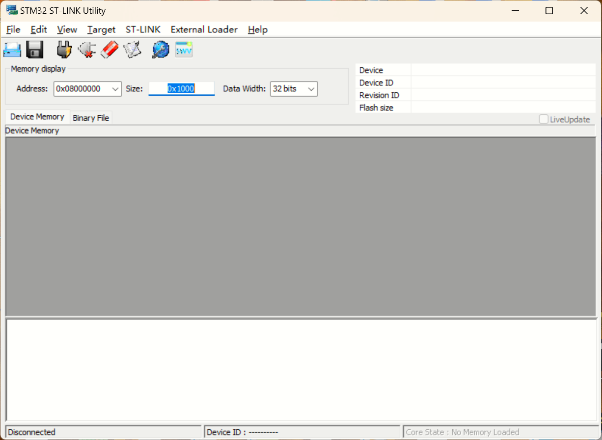
把刚才编译得到的hex文件烧录进STM32
这个软件的用法详见:https://www.bilibili.com/video/BV1LjojYxEm5
LED流水灯
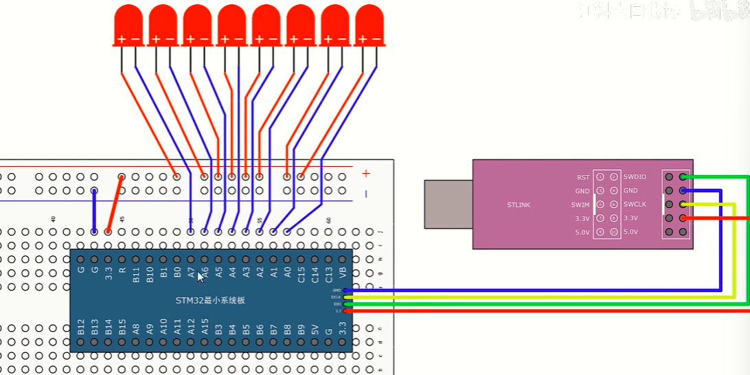
接线图
用标准库实现
#include "stm32f10x.h"                  // Device header
#include "Delay.h"

int main(void)
{
	//点亮PA0口的LED,需要RCC APB2外设 GIOPA
	//打开了APB2总线时钟
	RCC_APB2PeriphClockCmd(RCC_APB2Periph_GPIOA, ENABLE);
	GPIO_InitTypeDef GPIO_InitStruct; //GPIO外设参数结构体
	GPIO_InitStruct.GPIO_Mode = GPIO_Mode_Out_PP; //设置推挽输出
	//用或的方式打开多个端口
	GPIO_InitStruct.GPIO_Pin = GPIO_Pin_0 | GPIO_Pin_1 |
	GPIO_Pin_2 | GPIO_Pin_3 | GPIO_Pin_4 | GPIO_Pin_5 |
	GPIO_Pin_6 | GPIO_Pin_7;
	GPIO_InitStruct.GPIO_Speed = GPIO_Speed_50MHz; //端口配置50Mhz
	GPIO_Init(GPIOA, &GPIO_InitStruct); //初始化GPIO_Init
	while(1)
	{
		GPIO_Write(GPIOA, ~0x0001); //0000 0000 0000 0001 设置的是PA0低电平(按位取反)
		Delay_ms(100); //延迟50ms
		GPIO_Write(GPIOA, ~0x0002); //0000 0000 0000 0010 设置的是PA1低电平(按位取反)
		Delay_ms(100); //延迟50ms
		GPIO_Write(GPIOA, ~0x0004); //0000 0000 0000 0100 设置的是PA2低电平(按位取反)
		Delay_ms(100); //延迟50ms
		GPIO_Write(GPIOA, ~0x0008); //0000 0000 0000 1000 设置的是PA3低电平(按位取反)
		Delay_ms(100); //延迟50ms
		GPIO_Write(GPIOA, ~0x0010); //0000 0000 0001 0000 设置的是PA4低电平(按位取反)
		Delay_ms(100); //延迟50ms
		GPIO_Write(GPIOA, ~0x0020); //0000 0000 0010 0000 设置的是PA5低电平(按位取反)
		Delay_ms(100); //延迟50ms
		GPIO_Write(GPIOA, ~0x0040); //0000 0000 0100 0000 设置的是PA6低电平(按位取反)
		Delay_ms(100); //延迟50ms
		GPIO_Write(GPIOA, ~0x0080); //0000 0000 1000 0000 设置的是PA7低电平(按位取反)
		Delay_ms(100); //延迟50ms
		//高8位暂时不用
	}
}
此时LED流水灯依次亮起来
用HAL库实现
新建工程,把GPIO A0-A7口全都设置为输出模式,然后都是默认高电平,推挽输出(图形化界面设置)
main.c
/* USER CODE BEGIN Header */
/**
  ******************************************************************************
  * @file           : main.c
  * @brief          : Main program body
  ******************************************************************************
  * @attention
  *
  * Copyright (c) 2025 STMicroelectronics.
  * All rights reserved.
  *
  * This software is licensed under terms that can be found in the LICENSE file
  * in the root directory of this software component.
  * If no LICENSE file comes with this software, it is provided AS-IS.
  *
  ******************************************************************************
  */
/* USER CODE END Header */
/* Includes ------------------------------------------------------------------*/
#include "main.h"

/* Private includes ----------------------------------------------------------*/
/* USER CODE BEGIN Includes */

/* USER CODE END Includes */

/* Private typedef -----------------------------------------------------------*/
/* USER CODE BEGIN PTD */

/* USER CODE END PTD */

/* Private define ------------------------------------------------------------*/
/* USER CODE BEGIN PD */

/* USER CODE END PD */

/* Private macro -------------------------------------------------------------*/
/* USER CODE BEGIN PM */

/* USER CODE END PM */

/* Private variables ---------------------------------------------------------*/

/* USER CODE BEGIN PV */

/* USER CODE END PV */

/* Private function prototypes -----------------------------------------------*/
void SystemClock_Config(void);
static void MX_GPIO_Init(void);
/* USER CODE BEGIN PFP */

/* USER CODE END PFP */

/* Private user code ---------------------------------------------------------*/
/* USER CODE BEGIN 0 */

/* USER CODE END 0 */

/**
  * @brief  The application entry point.
  * @retval int
  */
int main(void)
{

  /* USER CODE BEGIN 1 */

  /* USER CODE END 1 */

  /* MCU Configuration--------------------------------------------------------*/

  /* Reset of all peripherals, Initializes the Flash interface and the Systick. */
  HAL_Init();

  /* USER CODE BEGIN Init */

  /* USER CODE END Init */

  /* Configure the system clock */
  SystemClock_Config();

  /* USER CODE BEGIN SysInit */

  /* USER CODE END SysInit */

  /* Initialize all configured peripherals */
  MX_GPIO_Init();
  /* USER CODE BEGIN 2 */

  /* USER CODE END 2 */

  /* Infinite loop */
  /* USER CODE BEGIN WHILE */
  while (1)
  {
	  // 依次点亮PA0~PA7(低电平有效,通过直接操作ODR寄存器实现)
	  GPIOA->ODR = ~0x0001;  // PA0输出低电平,其他高电平
	  HAL_Delay(100);        // 延迟100ms(HAL库自带延迟函数)

	  GPIOA->ODR = ~0x0002;  // PA1输出低电平
	  HAL_Delay(100);

	  GPIOA->ODR = ~0x0004;  // PA2输出低电平
	  HAL_Delay(100);

	  GPIOA->ODR = ~0x0008;  // PA3输出低电平
	  HAL_Delay(100);

	  GPIOA->ODR = ~0x0010;  // PA4输出低电平
	  HAL_Delay(100);

	  GPIOA->ODR = ~0x0020;  // PA5输出低电平
	  HAL_Delay(100);

	  GPIOA->ODR = ~0x0040;  // PA6输出低电平
	  HAL_Delay(100);

	  GPIOA->ODR = ~0x0080;  // PA7输出低电平
	  HAL_Delay(100);
    /* USER CODE END WHILE */

    /* USER CODE BEGIN 3 */
  }
  /* USER CODE END 3 */
}

/**
  * @brief System Clock Configuration
  * @retval None
  */
void SystemClock_Config(void)
{
  RCC_OscInitTypeDef RCC_OscInitStruct = {0};
  RCC_ClkInitTypeDef RCC_ClkInitStruct = {0};

  /** Initializes the RCC Oscillators according to the specified parameters
  * in the RCC_OscInitTypeDef structure.
  */
  RCC_OscInitStruct.OscillatorType = RCC_OSCILLATORTYPE_HSI;
  RCC_OscInitStruct.HSIState = RCC_HSI_ON;
  RCC_OscInitStruct.HSICalibrationValue = RCC_HSICALIBRATION_DEFAULT;
  RCC_OscInitStruct.PLL.PLLState = RCC_PLL_NONE;
  if (HAL_RCC_OscConfig(&RCC_OscInitStruct) != HAL_OK)
  {
    Error_Handler();
  }

  /** Initializes the CPU, AHB and APB buses clocks
  */
  RCC_ClkInitStruct.ClockType = RCC_CLOCKTYPE_HCLK|RCC_CLOCKTYPE_SYSCLK
                              |RCC_CLOCKTYPE_PCLK1|RCC_CLOCKTYPE_PCLK2;
  RCC_ClkInitStruct.SYSCLKSource = RCC_SYSCLKSOURCE_HSI;
  RCC_ClkInitStruct.AHBCLKDivider = RCC_SYSCLK_DIV1;
  RCC_ClkInitStruct.APB1CLKDivider = RCC_HCLK_DIV1;
  RCC_ClkInitStruct.APB2CLKDivider = RCC_HCLK_DIV1;

  if (HAL_RCC_ClockConfig(&RCC_ClkInitStruct, FLASH_LATENCY_0) != HAL_OK)
  {
    Error_Handler();
  }
}

/**
  * @brief GPIO Initialization Function
  * @param None
  * @retval None
  */
static void MX_GPIO_Init(void)
{
  GPIO_InitTypeDef GPIO_InitStruct = {0};
  /* USER CODE BEGIN MX_GPIO_Init_1 */

  /* USER CODE END MX_GPIO_Init_1 */

  /* GPIO Ports Clock Enable */
  __HAL_RCC_GPIOA_CLK_ENABLE();

  /*Configure GPIO pin Output Level */
  HAL_GPIO_WritePin(GPIOA, GPIO_PIN_0|GPIO_PIN_1|GPIO_PIN_2|GPIO_PIN_3
                          |GPIO_PIN_4|GPIO_PIN_5|GPIO_PIN_6|GPIO_PIN_7, GPIO_PIN_SET);

  /*Configure GPIO pins : PA0 PA1 PA2 PA3
                           PA4 PA5 PA6 PA7 */
  GPIO_InitStruct.Pin = GPIO_PIN_0|GPIO_PIN_1|GPIO_PIN_2|GPIO_PIN_3
                          |GPIO_PIN_4|GPIO_PIN_5|GPIO_PIN_6|GPIO_PIN_7;
  GPIO_InitStruct.Mode = GPIO_MODE_OUTPUT_PP;
  GPIO_InitStruct.Pull = GPIO_NOPULL;
  GPIO_InitStruct.Speed = GPIO_SPEED_FREQ_LOW;
  HAL_GPIO_Init(GPIOA, &GPIO_InitStruct);

  /* USER CODE BEGIN MX_GPIO_Init_2 */

  /* USER CODE END MX_GPIO_Init_2 */
}

/* USER CODE BEGIN 4 */

/* USER CODE END 4 */

/**
  * @brief  This function is executed in case of error occurrence.
  * @retval None
  */
void Error_Handler(void)
{
  /* USER CODE BEGIN Error_Handler_Debug */
  /* User can add his own implementation to report the HAL error return state */
  __disable_irq();
  while (1)
  {
  }
  /* USER CODE END Error_Handler_Debug */
}

#ifdef  USE_FULL_ASSERT
/**
  * @brief  Reports the name of the source file and the source line number
  *         where the assert_param error has occurred.
  * @param  file: pointer to the source file name
  * @param  line: assert_param error line source number
  * @retval None
  */
void assert_failed(uint8_t *file, uint32_t line)
{
  /* USER CODE BEGIN 6 */
  /* User can add his own implementation to report the file name and line number,
     ex: printf("Wrong parameters value: file %s on line %d\r\n", file, line) */
  /* USER CODE END 6 */
}
#endif /* USE_FULL_ASSERT */
hal库没有GPIOWrite这样的寄存器,只能直接设置寄存器

 浙公网安备 33010602011771号