
Modbus采集 + MQTT传输 分控板控制协议 Modbus 协议
在工业物联网(IIoT)架构中,Modbus扮演着连接传统设备与现代云平台的关键桥梁角色:
-
边缘采集层:通过Modbus RTU/TCP采集现场设备数据
-
协议转换:使用物联网网关将Modbus转换为MQTT等云协议
-
数据上云:将工业数据上传至云端进行AI分析与可视化展示
这种Modbus采集 + MQTT传输的组合架构,已成为工业物联网数据采集的事实标准。
报文实例:读取保持寄存器
以读取从站地址1的保持寄存器(起始地址0x0000,读取2个寄存器)为例:
主站请求帧:01 03 00 00 00 02 C4 0B
| 字节 | 值 | 含义 |
|---|---|---|
| 1 | 0x01 | 从站地址=1 |
| 2 | 0x03 | 功能码=读保持寄存器 |
| 3-4 | 0x00 0x00 | 起始地址=0(对应寄存器40001) |
| 5-6 | 0x00 0x02 | 读取2个寄存器 |
| 7-8 | 0xC4 0x0B | CRC-16校验码 |
从站正常响应帧:01 03 04 00 0A 00 14 84 0A
| 字节 | 值 | 含义 |
|---|---|---|
| 1 | 0x01 | 从站地址回显 |
| 2 | 0x03 | 功能码回显 |
| 3 | 0x04 | 后续数据字节数(4字节) |
| 4-5 | 0x00 0x0A | 第1个寄存器值=10 |
| 6-7 | 0x00 0x14 | 第2个寄存器值=20 |
| 8-9 | 0x84 0x0A | CRC-16校验码 |
🏗️ 核心架构:主从模式
Modbus采用主从(Master/Slave)通信模型,也叫客户端-服务器模型:
-
主站:通信的发起者,一个网络中有且只有一个主站
-
从站:响应主站请求的设备,一个网络中最多可连接247个从站(地址范围1-247)
-
广播地址0:主站可向地址0发送广播命令,所有从站都接收执行,但无需响应
通信过程遵循请求-响应机制:只有主站能发起通信,从站只能被动响应,不能主动发送数据或与其他从站通信。
📦 数据模型:四种寄存器
Modbus定义了四种数据类型,每个类型有独立的地址空间:
| 数据类型 | 大小 | 访问权限 | 实际用途 |
|---|---|---|---|
| 线圈(Coil) | 1位 | 可读写 | 控制继电器、开关等输出设备 |
| 离散输入(Discrete Input) | 1位 | 只读 | 读取按钮、传感器开关状态 |
| 保持寄存器(Holding Register) | 16位 | 可读写 | 存储设备参数、设定值 |
| 输入寄存器(Input Register) | 16位 | 只读 | 采集模拟量数据(温度、压力、电压) |
关于地址编号:Modbus协议中实际传输的地址从0开始(零基地址),但很多设备厂商在文档中使用基于1的地址编号(如40001、30002),通信时需要转换:第n号寄存器的地址 = n-1。
🎯 功能码:操作指令集
功能码决定了要执行的具体操作,位于报文中的第二个字节:
| 功能码(Hex) | 功能名称 | 操作对象 |
|---|---|---|
| 0x01 | 读线圈 | 读取一个或多个线圈状态 |
| 0x02 | 读离散输入 | 读取一个或多个离散输入状态 |
| 0x03 | 读保持寄存器 | 读取一个或多个保持寄存器的值 |
| 0x04 | 读输入寄存器 | 读取一个或多个输入寄存器的值 |
| 0x05 | 写单个线圈 | 写入单个线圈 |
| 0x06 | 写单个寄存器 | 写入单个保持寄存器 |
| 0x0F | 写多个线圈 | 写入多个线圈 |
| 0x10 | 写多个寄存器 | 写入多个保持寄存器 |
异常处理:当从站无法执行请求时,会返回异常响应。此时响应中的功能码 = 请求功能码 + 0x80,数据域携带异常码(如01=非法功能,02=非法数据地址)。
📡 三种主要实现形式
| 特性 | Modbus RTU | Modbus ASCII | Modbus TCP |
|---|---|---|---|
| 物理层 | RS-232/RS-485串口 | RS-232/RS-485串口 | 以太网(TCP/IP) |
| 数据编码 | 二进制 | ASCII字符 | 二进制 |
| 帧界定 | 时间间隔(3.5字符静默) | 起始符:、结束符CR/LF |
TCP连接 |
| 校验机制 | CRC-16(2字节) | LRC(1字节) | 依赖TCP校验 |
| 传输效率 | 高 | 低(文本冗长) | 高 |
| 调试便利性 | 需专用工具 | 可直接阅读 | 需网络抓包 |
| 适用场景 | 工业现场串行链路 | 低速调试环境 | 以太网/物联网 |
RTU是目前最主流的串行实现,在工厂车间、能源管理等场景中应用最为广泛。
🔐 安全性与局限性
Modbus协议的设计初衷是工业内部网络的简单高效通信,因此存在一些先天不足:
-
无加密机制:所有数据(包括密码、控制指令)以明文传输
-
无身份认证:任何能访问网络的设备都可以成为主站
-
易受攻击:中间人攻击、伪造指令、重放攻击等
安全加固方案:
-
通过VPN隧道(IPsec/SSL/TLS)加密通信
-
物理隔离(专用工业网络)
-
部署工业防火墙,设置访问控制白名单
-
使用Modbus Security扩展(RFC 8981,添加TLS加密和认证)
分控板控制协议 Modbus 协议
详解modbus-上 - 知乎 https://zhuanlan.zhihu.com/p/77502146
Modbus通讯协议_百度百科 https://baike.baidu.com/item/Modbus%E9%80%9A%E8%AE%AF%E5%8D%8F%E8%AE%AE/5972462?fromtitle=ModBus&fromid=305501&fr=aladdin
An Introduction to the Modbus Communication Protocol https://www.solisplc.com/tutorials/modbus
The Modbus Organization https://modbus.org/
Introduction to the modbus protocol
Original equipment manufacturers (OEMs) all have proprietary communication protocols such as Profinet, CIP, DeviceNet, and ControlNet used to communicate with all their devices on the plant floor. As we know, there are different manufacturers of controllers, instruments, and peripheral devices, which leaves the question of how to make them exchange data with each other. This led to open-source protocols that bridge the gap left by proprietary protocols in communicating with third-party devices. Standard open protocols are Modbus, OPC DA, OPC UA, MQTT. This article will look in-depth into the MODBUS protocol, its benefits, types, and implementation.
What is Modbus
MODBUS is a communication protocol developed by Modicon in 1979 (now Schneider Electric) used by programmable logic controllers. Modbus transmission of data can be over serial lines or ethernet. Many devices are now Modbus compliant since it's now a widely accepted communication protocol. Supervisory Control and Data Acquisition mainly use Modbus (SCADA) to receive data from remote terminal units (RTU) and PLCs.
Modbus communication types
Modbus can be grouped into three broad types:
- Modbus RTU
- Modbus ASCII
- Modbus TCP
Modbus RTU
Modbus RTU is the most often used Modbus protocol. Modbus RTU is a straightforward serial protocol that may be sent using standard UART technology. At baud speeds ranging from 1200 bits per second (baud) to 115200 bits per second, data is delivered in 8-bit bytes, one bit at a time. The majority of Modbus RTU devices support only 38400 bits per second. A Modbus RTU operates a Master to slave structure. A Modbus master can connect with up to 254 slaves and exchange data. Each slave has its own 8-bit device address, often known as a unit number. The address of the slave for whom the communication is intended is included in the packets transmitted by the master. The slave must only answer if its address is recognized, and it must do so within a specific amount of time, or the master will consider it a "no response" error.
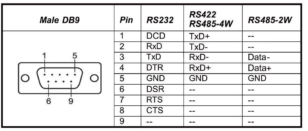
A slave is any peripheral device that analyzes data and delivers a response message to the master using Modbus, such as an I/O transducer, valve, network drive, or other measuring devices. The communication media for an RTU network is serial, either using RS232, RS422, or RS485.
Modbus ASCII
Modbus ASCII is an older version of the protocol that contains all of the elements of an RTU packet but is entirely written in understandable ASCII characters. Modbus ASCII isn't supported, isn't widely used, and isn't included in the official Modbus protocol specification.
Modbus Protocol TCP
Since its inception, Ethernet IP/TCP has been the most common network protocol. Modbus TCP wraps Modbus RTU data packets in a TCP packet that can be sent over conventional Ethernet networks. In TCP, the slave address is not the primary method of addressing. The IP address, for example, 192.168.0.20, is the most essential here. The regular Modbus TCP port is 502, but it is frequently reconfigured if necessary. Modbus TCP follows the OSI network model.
Modbus shifts from the conventional master to slave relationship to the client to server, where the master becomes the client and the slave the server. There can be multiple clients and multiple slaves, which is one of the beauties of Modbus TCP made possible through the peer-to-peer communication of Ethernet IP. A standard RJ 45 cable (LAN) is used for physically connecting Modbus TCP compliant devices.
Modbus message structure
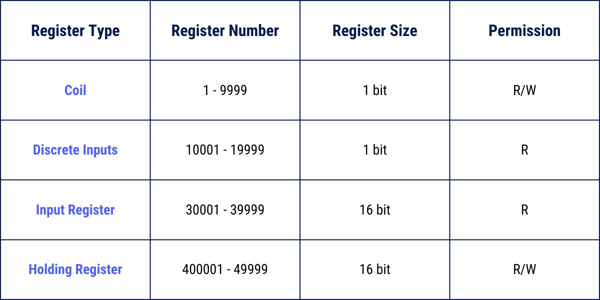
To be able to use any technology to its full capacity, it is pertinent to understand how it functions. Modbus makes use of registers in sending the different types of data. Registers are like ‘buckets’ that house data points. Some of the registers used in Modbus include the following;
- Discrete inputs (contacts): Discrete inputs are bit contact registers, and they can only be read. They can best be described as the contacts in PLC programming.
- Discrete Outputs (Coils): Coils are one-bit registers used as outputs. They are both read and write registers.
- Input registers: Inputs registers are 16-bit registers used for inputs. They are read only.
- Holding registers: Holding registers are 16-bit registers that are both read and write. They are the most universal register as they can be used for inputs, outputs, and for holding any kind of data.
Modbus function codes
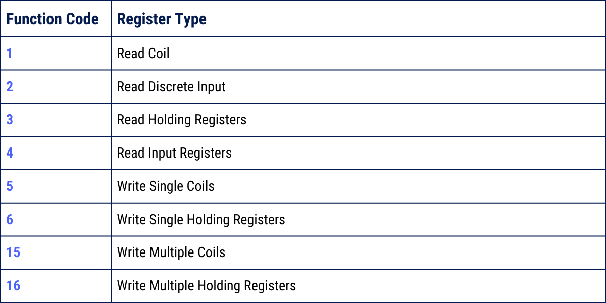
The Modbus protocol specifies the number of function codes that can be used to access Modbus registers. Modbus defines four separate data blocks, each with addresses or register numbers that overlap. As a result, both the address (or register number) and the function code are required to comprehensively explain where to find a piece of data (or register type).
The function codes recognized by Modbus are listed in the table below. Although this is not an exhaustive list of function codes, they are the most used and important ones to familiarize with.
Modbus error (exception) code explanation
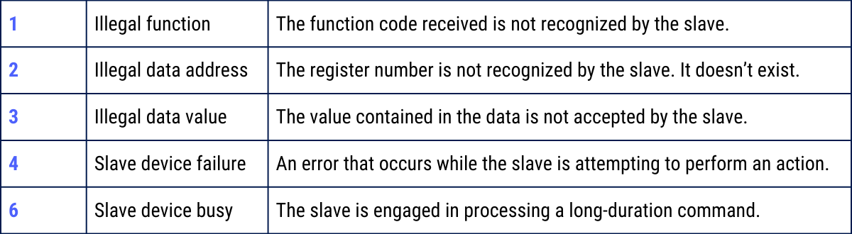
When a Modbus slave detects a packet but concludes that the request contains an error, it responds with an exception code rather than a data response. The slave address or unit number, a copy of the function code with the high bit set, and an exception code make up the exception reply.
Conclusion
This is only an introduction to what the Modbus protocol is all about. Numerous resources on the internet will explain some of these concepts. I encourage the reader to explore some of these resources. The Modbus protocol is a versatile industrial network protocol that has gained relevance in the automation society; hence having a good understanding is imperative.

 浙公网安备 33010602011771号