ESP8266 RTOS SDK开发
ESP8266 RTOS SDK开发
源码RTOS SDK包的下载和编译
SDK 版本: 18c3a1944ac3b1454a87e578705cd90026525608
git clone https://gitee.com/xuhongv/ESP8266_RTOS_SDK.git

修改.gitmodules文件
[submodule "components/json/cJSON"]
        path = components/json/cJSON
        url = https://gitee.com/xuhongv/cJSON.git
[submodule "components/mbedtls/mbedtls"]
        path = components/mbedtls/mbedtls
        url = https://gitee.com/xuhongv/mbedtls.git
[submodule "components/lwip/lwip"]
        path = components/lwip/lwip
        url = https://gitee.com/xuhongv/esp-lwip.git
[submodule "components/mqtt/esp-mqtt"]
        path = components/mqtt/esp-mqtt
        url = https://gitee.com/xuhongv/esp-mqtt.git
[submodule "components/coap/libcoap"]
        path = components/coap/libcoap
        url = https://gitee.com/xuhongv/libcoap.git
更新子模块
git submodule update --init --recursive
添加环境变量
export IDF_PATH=~/Esp/ESP8266_RTOS_SDK
export ~/Esp/Toolchain/xtensa-lx106-elf/bin
python -m pip install --user -r /home/mo/Esp/ESP8266_RTOS_SDK/requirements.txt
固件烧录
1.管脚定义
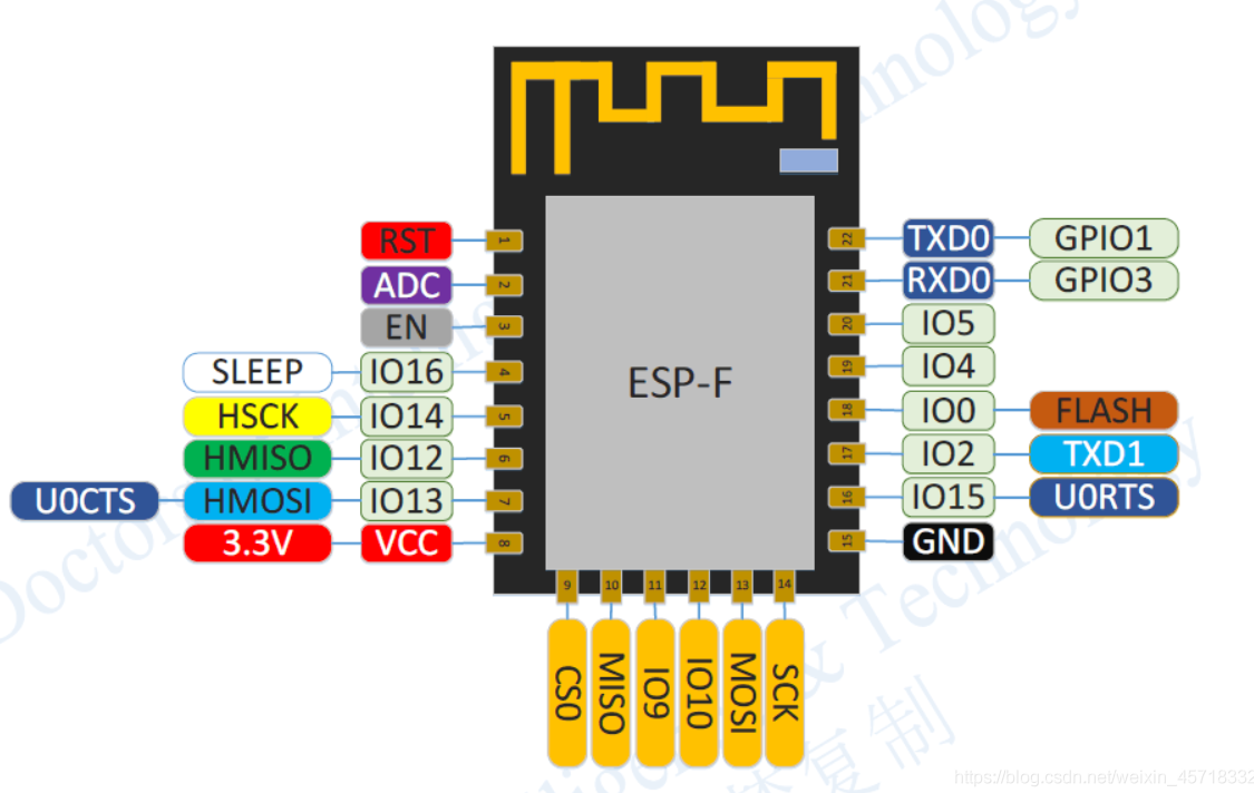
| 模式 | CH_PD(EN) | RST | GPIO15 | GPIO0 | GPIO2 | TXD0 |
|---|---|---|---|---|---|---|
| 下载模式 | 高 | 高 | 低 | 低 | 高 | 高 |
| 运行模式 | 高 | 高 | 低 | 高 | 高 | 高 |
| 测试模式 | 高 | 高 | - | - | - | 低 |
注:GPIO6~GPIO11被用于连接开发板的闪存(Flash Memory)因此建议不要使用GPIO6~GPIO11。请谨慎使用GPIO10,请勿使用GPIO9。(IO2 log调试默认波特率74880)
内存分布
ESP8266 的内存分布涉及不同类型的存储区域,包括指令 RAM(IRAM)、数据 RAM(DRAM)、闪存和 RTC 内存。
在ESP8266_RTOS_SDK中的esp8266.ld中:
MEMORY
{
  /* All these values assume the flash cache is on, and have the blocks this uses subtracted from the length
  of the various regions. */

  /* IRAM for cpu. The length is due to the cache mode which is able to be set half or full mode. */
  iram0_0_seg (RX) :                 org = 0x40100000, len = CONFIG_SOC_IRAM_SIZE

  /* Even though the segment name is iram, it is actually mapped to flash and mapped constant data */
  iram0_2_seg (RX) :                 org = 0x40200010 + (APP_OFFSET & (0x100000 - 1)),
                                     len = APP_SIZE - 0x10

  /*
    (0x18 offset above is a convenience for the app binary image generation. The .bin file which is flashed
    to the chip has a 0x10 byte file header. Setting this offset makes it simple to meet the flash cache.)
  */


  /* Length of this section is 96KB */
  dram0_0_seg (RW) :                 org = 0x3FFE8000, len = 0x18000

  /* (See iram0_2_seg for meaning of 0x10 offset in the above.) */

  /* RTC memory. Persists over deep sleep */
  rtc_data_seg(RW) :                 org = 0x60001200, len = 0x200
}
内存映射示意图
0x3F400000 |---------------------------|
           |       DROM (Data ROM)     |
           |---------------------------|
0x3FFE8000 |---------------------------|
           |       DRAM (Data RAM)     |
           |---------------------------|
0x40100000 |---------------------------|
           |   IRAM (Instruction RAM)  |
           |---------------------------|
0x40200000 |---------------------------|
           |IROM(Flash Instruction ROM)|
           |---------------------------|
0x60001200 |---------------------------|
           |       RTC RAM             |
           |---------------------------|
- IRAM (iram0_0_seg 和 iram0_2_seg): 用于存储指令和常量数据。地址和长度配置是为了适应缓存模式的设置。
- DRAM (dram0_0_seg): 用于存储动态数据,包括全局变量和堆栈数据。该段内存的配置固定为 96KB。
- RTC 内存 (rtc_data_seg): 用于存储需要在深度睡眠模式下保留的数据,通常用于保存系统状态或关键数据。
典型的内存分布示例:
0x3FFE8000: .data, .bss
0x3FFF0000: .heap_start
0x3FFF8000: .heap_end (动态分配区)
0x40100000: .text (IRAM 中的代码)
0x40200000: .irom0.text (从闪存中映射的代码)
如何查看内存分布
ESP8266 SDK 提供了一些工具和函数来查看内存的使用情况:
- heap_caps_get_free_size():获取可用的堆大小。
- heap_caps_get_largest_free_block():获取最大的连续可用堆块大小。
- system_get_free_heap_size():获取剩余的堆大小。
修改内存分配
可通过修改链接脚本esp8266.project.ld.in来调整内存分配。
- 找到/ESP8266_RTOS_SDK/components/esp8266/ld/esp8266.project.ld.in
- 调整 _bss_end 的地址来改变堆的大小。例如,将 _bss_end 向后移动以增加堆大小。
.dram0.bss (NOLOAD) :
{
    . = ALIGN (8);
    _bss_start = ABSOLUTE(.);

    mapping[dram0_bss]

    *(.dynsbss)
    *(.sbss)
    *(.sbss.*)
    *(.gnu.linkonce.sb.*)
    *(.scommon)
    *(.sbss2)
    *(.sbss2.*)
    *(.gnu.linkonce.sb2.*)
    *(.dynbss)
    *(.share.mem)
    *(.gnu.linkonce.b.*)

    . = ALIGN (8);
    _bss_end = ABSOLUTE(. + 0x1000);  /* 增加 0x1000 大小的堆 */
} > dram0_0_seg
注意,这里 0x1000 是增加的堆大小,你可以根据需要调整这个值。
程序例程
1.PWM设置
频率范围:100Hz ~ 1kHz
#include <stdio.h>
#include <string.h>
#include <stdlib.h>

#include "freertos/FreeRTOS.h"
#include "freertos/task.h"
#include "freertos/queue.h"

#include "esp_log.h"
#include "esp_system.h"
#include "esp_err.h"

#include "esp8266/gpio_register.h"
#include "esp8266/pin_mux_register.h"

#include "driver/pwm.h"

#define PWM_0_OUT_IO_NUM 15

static const char *TAG = "main";

// pwm pin number
const uint32_t pin_num[1] = {PWM_0_OUT_IO_NUM};

// phase table, delay = (phase[x]/360)*PERIOD
float phase[1] = {0};

void buzzer_freq_set(uint32_t freq)
{
    uint32_t period = 1000000 / freq;
    uint32_t duty   = period / 2;

    pwm_set_period(period);
    pwm_set_duty(0, duty);
    pwm_start();
}

void app_main()
{
    uint32_t pwm_period = 1000;    // 1kHz
    uint32_t pwm_duty   = 500;

    ESP_LOGI(TAG, "M.Y.Dodo\n");
    pwm_init(pwm_period, &pwm_duty, 1, pin_num);
    // pwm_set_phases(phase);
    pwm_start();

    uint32_t freq = 100;
    buzzer_freq_set(freq);

    int16_t count = 0;

    while (1) {
        count++;
        if (count == 3) {
            count = 0;
            freq += 100;
            buzzer_freq_set(freq);
        }

        vTaskDelay(1000 / portTICK_RATE_MS);
    }
}
连接MQTT
强制门户认证
强制门户:它的原理是DNS劫持,在手机等设备连接热点后,会尝试去请求DNS服务器获取一些网址的IP地址,此时wifi设备端就可以监听请求包,然后将自己的IP地址作为DNS解析结果返回给连接设备。
DNS采用UDP协议,端口号是53。
连接wifi后,手机自动弹出一个网页,跳转wifi配网页面。
注意
连接 Wi-Fi 时扫描AP会失败
如果 Wi-Fi 正在连接,则调用函数 esp_wifi_scan_start() 后扫描将立即失败,因为 Wi-Fi 连接优先级高于扫描。如果扫描是因为 Wi-Fi 连接而失败的,此时推荐采取的策略为:等待一段时间后重试。因为一旦 Wi-Fi 连接完成后,扫描将立即成功。
错误处理
Guru Meditation Error报错定位分析
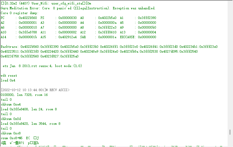
打印了异常时,PC、PS等各个寄存器的值,其中Backtrace打印了可能异常的地方,可以根据这个定位到具体对应的代码。
在终端输入
xtensa-lx106-elf-addr2line -pfiaC -e build/PROJECT_NAME.elf ADDRESS 0x4022b560:0x3fff2390 0x4022b5e0:0x3fff23b0 0x40226ff1:0x3fff23c0 0x40226f41:0x3fff23d0 0x402234b1:0x3fff23e0 0x40223511:0x3fff23f0 0x40224420:0x3fff2440 0x402248e9:0x3fff24e0 0x4023fb8a:0x3fff2530 0x4027d095:0x3fff2540 0x4023f758:0x3fff2560 0x4023f827:0x3fff25a0
使用 cJSON_PrintUnformatted函数时始终返回NULL
原因:由于 'nano' 版本是简化版,某些复杂的格式化功能可能会受到限制。
解决方法:make menuconfig > Component config > Newlib > [ ] Enable 'nano' formatting options for printf/scanf family 取消此项选择

 浙公网安备 33010602011771号