
一、前言
APU系统中CPU以串行执行代码的方式完成操作,软件方式很难做到精准计时,因此调用内部定时器硬件完成计时是更好的选择。本文以定时器中断方式控制LED周期性闪烁为例学习私有定时器的使用。同时学习如何将软件程序与硬件比特流文件一起固化到SD卡中,实现上电自动配置与启动自定义系统。
功能定义:通过定时器中断实现与MIO连接的单个LED每200ms变化依次电平,即点亮,200ms后熄灭,200ms后再次点亮,周期往复。
硬件平台:米联客Miz702N
软件工具:VIVADO 2017.4+SDK
二、硬件系统搭建
私有定时器属于APU内部专用硬件资源,无需在VIVADO中做出配置。由于需要将软硬件系统固化到SD卡中,选择与SD控制器连接的I/O。
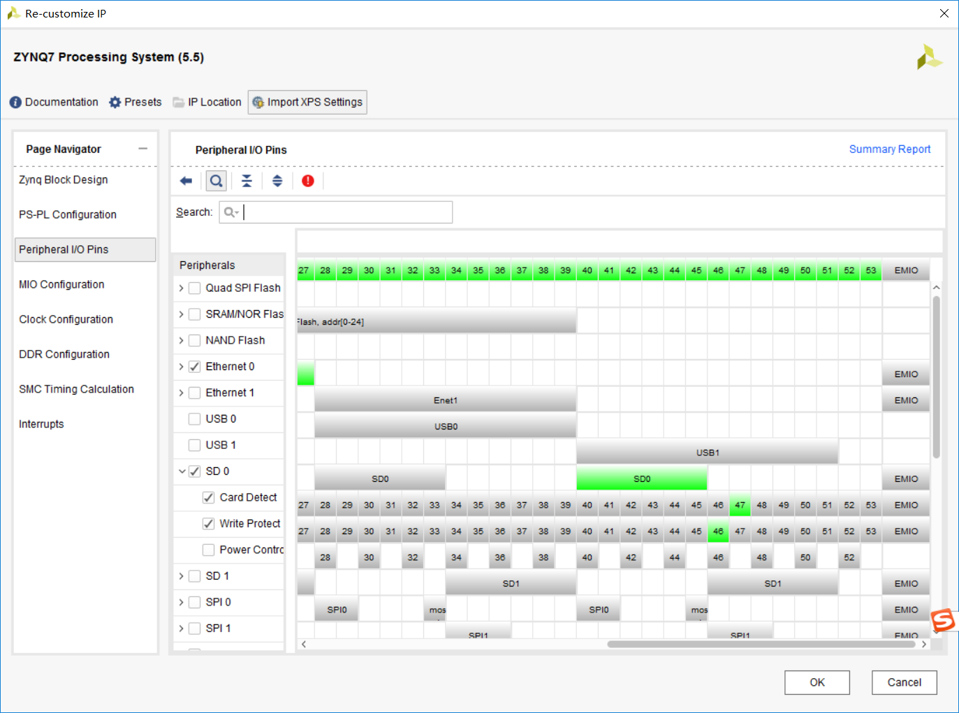
根据原理图,SD卡连接在MIO40~47,这也与UG585中的描述一致:

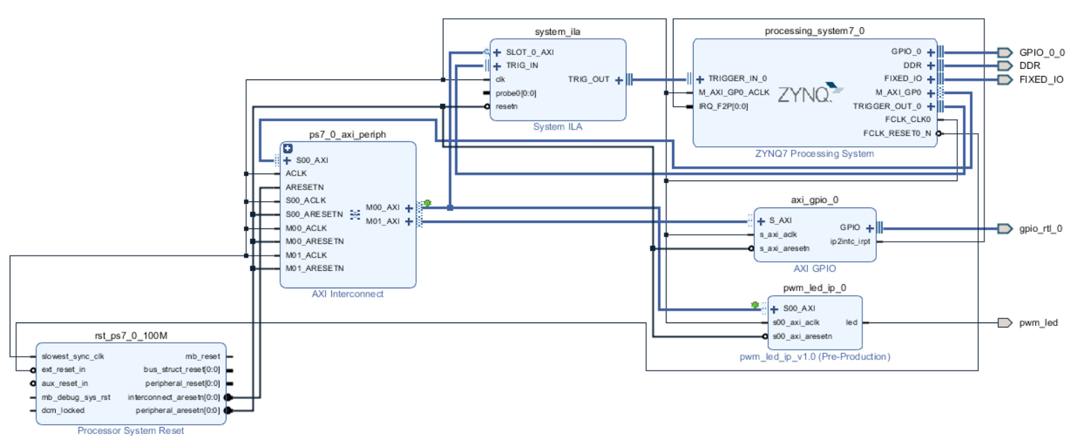
这里直接使用PWM产生呼吸灯效果工程中的硬件系统,可以更直观地观察出定时器控制LED与PWM控制LED互不影响。
依然是重新产生输出文件、生成HDL Wrapper、RUN Synthesis、Run Implementation、Generate bitstream、export Hardware with bitfile、Launch SDK. 剩下的任务均在SDK中完成。
三、软件设计
关于私有定时器使用方式,xilinx同样提供了文档和示例程序。

软件代码中使用的定时器相关函数均来自示例程序。使用私有定时器第一步当然是初始化配置,老套路调用XScuTimer_LookupConfig和XScuTimer_CfgInitialize两个函数。为了保证LED周期性闪烁,必须使能定时器的自动重载,这样每当计数器计数完成后会重新计数。之后最重要的是向定时器装载寄存器写入计数周期数值。实际上私有定时器是一个递减计数器,当从最大值递减到0时刻会产生定时器中断。如和将所要定时的时间长度换算为装载计数器周期数值呢?
很简单,n=t/T=t*f即可算出装载数值,其中n、t和T分别指所要定时的时间和定时器工作时钟周期。因为定时器工作时钟频率一直是CPU工作时钟的一半,在本系统中即为333MHz。这个n=200*10^(-3)*333*10^6=666*10^5。计数器是N-1~0的计数方式,装载值在n的基础上减1,对应的十六进制数值是0x3F83C3F。
装载完毕后调用XScuTimer_Start定时器随即开始工作。最后在定时器中断回调函数中对MIO进行反转操作就可以满足功能预期。另外,对之前PWM实现呼吸灯效果的工程做些改善,软件程序如下:


  1 /*
  2  * main.c
  3  *
  4  *  Created on: 2020年2月22日
  5  *      Author: s
  6  */
  7
  8
  9 #include "environment.h"
 10
 11
 12
 13 int main()
 14 {
 15     int Status;
 16     u8 i=0;
 17
 18     freq_step_value = 10;
 19
 20     Status = gpiops_initialize(&GpioPs,GPIOPS_DEVICE_ID);
 21     if (Status != XST_SUCCESS) {
 22         return XST_FAILURE;
 23     }
 24
 25     Status = gpio_initialize(&Gpio,GPIO_DEVICE_ID);
 26     if (Status != XST_SUCCESS) {
 27         return XST_FAILURE;
 28     }
 29
 30     Status = timer_initialize(&TimerInstance,TIMER_DEVICE_ID);
 31     if (Status != XST_SUCCESS) {
 32         return XST_FAILURE;
 33     }
 34     /*
 35      * Set the direction for the pin to be output and
 36     * Enable the Output enable for the LED Pin.
 37      */
 38     gpiops_setOutput(&GpioPs,MIO_OUT_PIN_INDEX);
 39
 40     for(i=0;i<LOOP_NUM;i++){
 41         gpiops_setOutput(&GpioPs,EMIO_OUT_PIN_BASE_INDEX+i);
 42     }
 43
 44     gpio_setDirect(&Gpio, 1,GPIO_CHANNEL1);
 45
 46     Status = setupIntSystem(&Intc,&Gpio,&TimerInstance,
 47             INTC_GPIO_INTERRUPT_ID,TIMER_IRPT_INTR);
 48     if (Status != XST_SUCCESS) {
 49             return XST_FAILURE;
 50         }
 51
 52     /*
 53     * Enable Auto reload mode.
 54     */
 55     XScuTimer_EnableAutoReload(&TimerInstance);
 56
 57     /*
 58     * Load the timer counter register.
 59     */
 60     XScuTimer_LoadTimer(&TimerInstance, TIMER_LOAD_VALUE);
 61
 62     /*
 63      * Start the timer counter and then wait for it
 64     * to timeout a number of times.
 65     */
 66     XScuTimer_Start(&TimerInstance);
 67
 68
 69
 70     Status = pwm_led_setFreqStep(freq_step_value);
 71     if (Status != XST_SUCCESS) {
 72             return XST_FAILURE;
 73         }
 74
 75     printf("Initialization finish.\n");
 76
 77     while(1){
 78
 79         for(i=0;i<LOOP_NUM;i++){
 80             if(int_flag == 0)
 81             {
 82                 gpiops_outputValue(&GpioPs, EMIO_OUT_PIN_BASE_INDEX+i, 0x1);
 83                 usleep(200*1000);
 84                 gpiops_outputValue(&GpioPs, EMIO_OUT_PIN_BASE_INDEX+i, 0x0);
 85             }
 86             else
 87             {
 88                 gpiops_outputValue(&GpioPs, EMIO_OUT_PIN_BASE_INDEX+LOOP_NUM-1-i, 0x1);
 89                 usleep(200*1000);
 90                 gpiops_outputValue(&GpioPs, EMIO_OUT_PIN_BASE_INDEX+LOOP_NUM-1-i, 0x0);
 91             }
 92         }
 93
 94
 95     }
 96     return 0;
 97 }
 98
 99
100
101 int setupIntSystem(XScuGic *IntcInstancePtr,XGpio *gpioInstancePtr,
102         XScuTimer * TimerInstancePtr,u32 gpio_IntrId,u32 timer_IntrId)
103 {
104     int Result;
105     /*
106     * Initialize the interrupt controller driver so that it is ready to
107     * use.
108     */
109
110     Result = gic_initialize(&Intc,INTC_DEVICE_ID);
111     if (Result != XST_SUCCESS) {
112             return XST_FAILURE;
113         }
114
115     XScuGic_SetPriorityTriggerType(IntcInstancePtr, gpio_IntrId,
116                         0xA0, 0x3);
117
118     /*
119     * Connect the interrupt handler that will be called when an
120      * interrupt occurs for the device.
121      */
122     Result = XScuGic_Connect(IntcInstancePtr, gpio_IntrId,
123                 (Xil_ExceptionHandler)GpioHandler, gpioInstancePtr);
124     if (Result != XST_SUCCESS) {
125         return Result;
126     }
127
128     Result = XScuGic_Connect(IntcInstancePtr, timer_IntrId,
129                     (Xil_ExceptionHandler)TimerIntrHandler,
130                     (void *)TimerInstancePtr);
131     if (Result != XST_SUCCESS) {
132             return Result;
133         }
134
135     /* Enable the interrupt for the GPIO device.*/
136     XScuGic_Enable(IntcInstancePtr, gpio_IntrId);
137
138     /*
139      * Enable the GPIO channel interrupts so that push button can be
140     * detected and enable interrupts for the GPIO device
141     */
142     XGpio_InterruptEnable(gpioInstancePtr,GPIO_CHANNEL1);
143     XGpio_InterruptGlobalEnable(gpioInstancePtr);
144
145     /*
146     * Enable the interrupt for the device.
147     */
148     XScuGic_Enable(IntcInstancePtr, timer_IntrId);
149     XScuTimer_EnableInterrupt(TimerInstancePtr);
150
151     /*
152     * Initialize the exception table and register the interrupt
153     * controller handler with the exception table
154     */
155     exception_enable(&Intc);
156
157     IntrFlag = 0;
158
159     return XST_SUCCESS;
160 }
161
162 void GpioHandler(void *CallbackRef)
163 {
164     XGpio *GpioPtr = (XGpio *)CallbackRef;
165     u32 gpio_inputValue;
166
167
168     /* Clear the Interrupt */
169     XGpio_InterruptClear(GpioPtr, GPIO_CHANNEL1);
170     printf("gpio interrupt.\n");
171
172     //IntrFlag = 1;
173     gpio_inputValue = gpio_readValue(GpioPtr, 1);
174     switch(gpio_inputValue)
175     {
176     case 30:
177         //printf("button up\n");
178         usleep(5);
179         gpio_inputValue = gpio_readValue(GpioPtr, 1);
180         if(gpio_inputValue == 30){
181             freq_step_value = freq_step_value < FREQ_STEP_MAX ?
182                     freq_step_value+10 : freq_step_value;
183             printf("%d\n",freq_step_value);
184             pwm_led_setFreqStep(freq_step_value);
185         }
186         break;
187     case 29:
188         //printf("button center\n");
189         usleep(5);
190         gpio_inputValue = gpio_readValue(GpioPtr, 1);
191         if(gpio_inputValue == 29){
192             freq_step_value = FREQ_STEP_SET_VALUE;
193             pwm_led_setFreqStep(freq_step_value);
194         }
195         break;
196     case 27:
197         //printf("button left\n");
198         usleep(5);
199         gpio_inputValue = gpio_readValue(GpioPtr, 1);
200         if(gpio_inputValue == 27)
201             int_flag = 0;
202         break;
203     case 23:
204         //printf("button right\n");
205         usleep(5);
206         gpio_inputValue = gpio_readValue(GpioPtr, 1);
207         if(gpio_inputValue == 23)
208             int_flag = 1;
209         break;
210     case 15:
211         //print("button down\n");
212         usleep(5);
213         gpio_inputValue = gpio_readValue(GpioPtr, 1);
214         if(gpio_inputValue == 15){
215             freq_step_value = freq_step_value > FREQ_STEP_MIN ?
216                     freq_step_value-10 : freq_step_value;
217             printf("%d\n",freq_step_value);
218             pwm_led_setFreqStep(freq_step_value);
219         }
220         break;
221     }
222
223 }
224
225 void TimerIntrHandler(void *CallBackRef)
226 {
227     XScuTimer *TimerInstancePtr = (XScuTimer *) CallBackRef;
228
229     XScuTimer_ClearInterruptStatus(TimerInstancePtr);
230
231     gpiops_outputValue(&GpioPs, MIO_OUT_PIN_INDEX, sys_led_out);
232     sys_led_out  = sys_led_out == 0x0 ? 0x1 : 0x0;
233 }
 1 /*
 2  * timer.h
 3  *
 4  *  Created on: 2020年3月5日
 5  *      Author: s
 6  */
 7
 8 #ifndef SRC_TIMER_H_
 9 #define SRC_TIMER_H_
10
11 #include "xscutimer.h"
12
13 #define TIMER_DEVICE_ID        XPAR_XSCUTIMER_0_DEVICE_ID
14 #define TIMER_IRPT_INTR        XPAR_SCUTIMER_INTR
15
16 //333*n(ms)*10^3-1 = 333*5*1000-1 = 1664999 0x1967E7
17 #define TIMER_LOAD_VALUE    0x3F83C3F
18
19 int timer_initialize(XScuTimer * TimerInstancePtr,u16 TimerDeviceId);
20
21
22 #endif /* SRC_TIMER_H_ */
 1 /*
 2  * timer.c
 3  *
 4  *  Created on: 2020年3月5日
 5  *      Author: s
 6  */
 7
 8
 9 #include "timer.h"
10
11 int timer_initialize(XScuTimer * TimerInstancePtr,u16 TimerDeviceId)
12 {
13     XScuTimer_Config *ConfigPtr;
14     /*
15     * Initialize the Scu Private Timer driver.
16     */
17     ConfigPtr = XScuTimer_LookupConfig(TimerDeviceId);
18
19     /*
20     * This is where the virtual address would be used, this example
21     * uses physical address.
22     */
23     return XScuTimer_CfgInitialize(TimerInstancePtr, ConfigPtr,
24                     ConfigPtr->BaseAddr);
25 }
相比原来的程序,在GpioHandler中添加了对freq_step_value最值的限制以及按键消抖延时。
四、程序固化
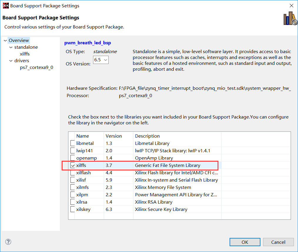
本工程固化程序时要使用FAT文件系统,更改板级支持包设置,勾选xilffs库并重新生成BSP。
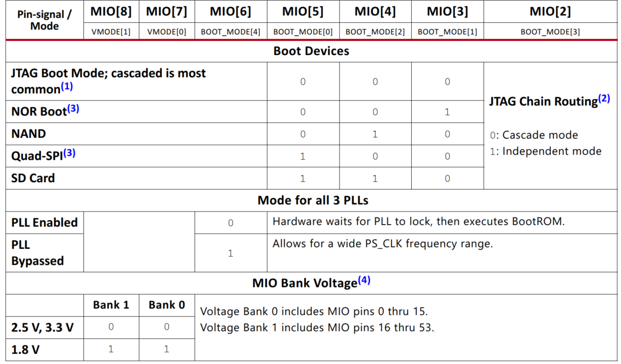
在固化程序之前,了解CPU的启动过程是非常必要的,这部分概念主要来自UG585文档。在上电复位后,硬件逻辑会根据启动模式引脚的高低电平选择启动方式。
硬件一些初始化操作后执行CPU内部一个ROM中的代码来启动整个系统,这个ROM的名字叫BootROM。BootROM中的程序是第一个被CPU执行的代码,其主要任务是配置系统,并从boot device中拷贝系统镜像到OCM,配置DDR操作。
Boot device可以是Quad-SPI,NAND,NOR或者SD卡。Boot device中存储的是boot image,其由BootROM Header和FSBL以及User Code组成,当然也可包括用于配置PL的bitstream和软件OS。软件boot分为三个阶段:

其中FSBL起到组织作用,将PS部分软件生成的ELF文件和PL部分硬件bit文件组合在一起。该文件利用xilinx的FSBL示例工程生成,用户无需关注内部实现细节。
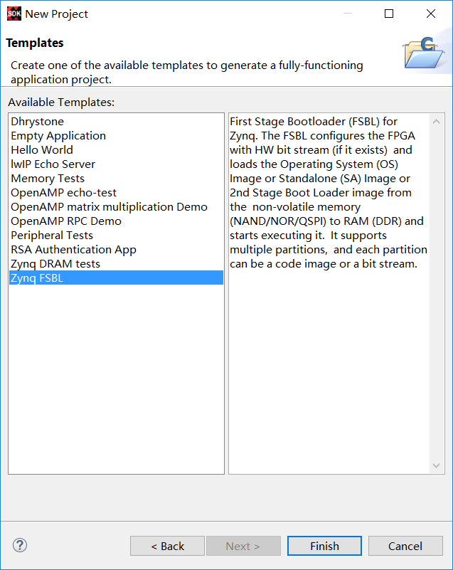
创建工程后会自动编译并生成ELF文件。点击工具栏xilinx -> create boot image。按照如下顺序添加三个文件:fsdb.elf --> bit --> <user_code>.elf
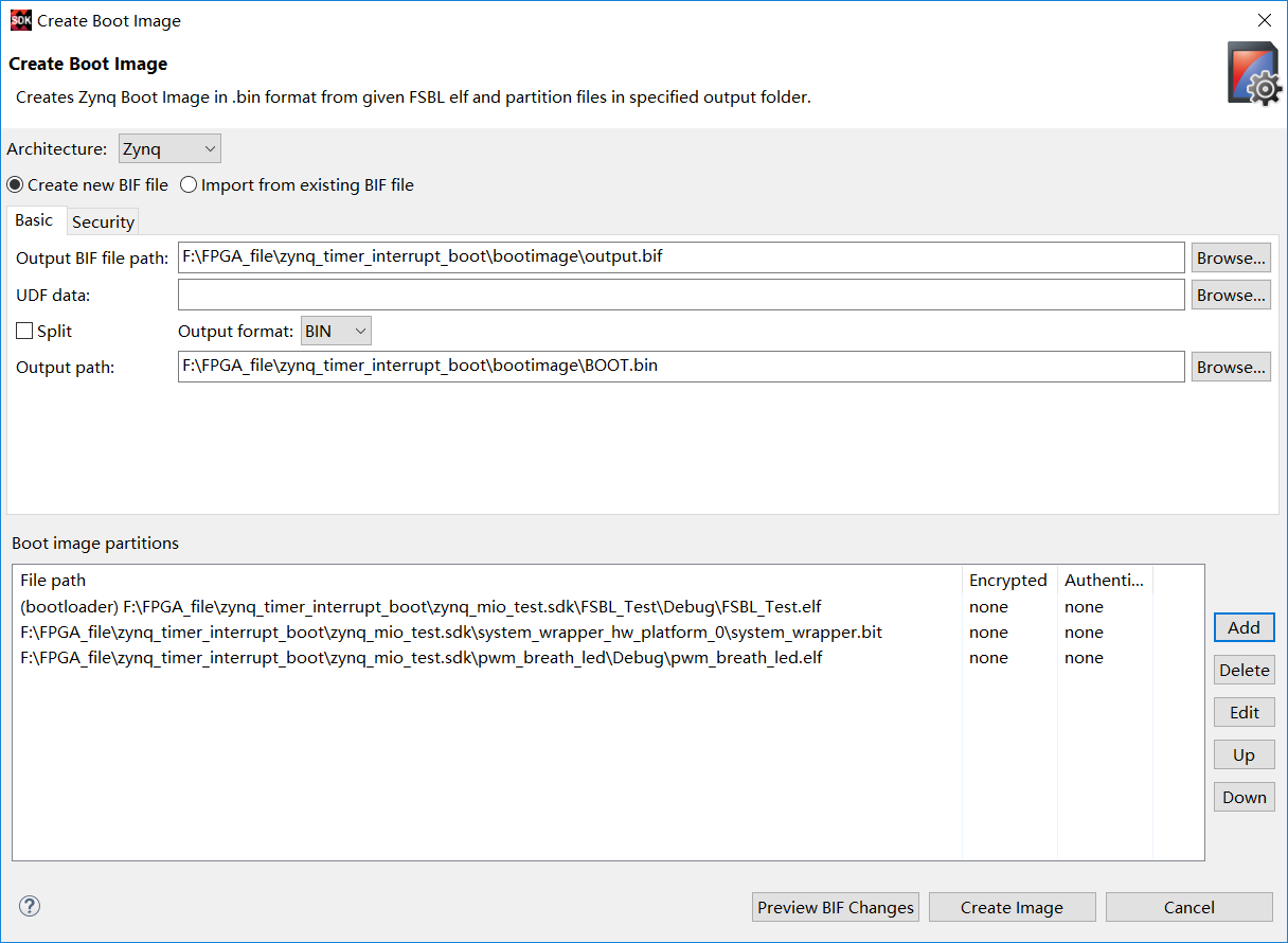
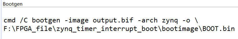
create image后会生成对应的bin文件,也就是之前阐述的启动镜像。
我们将BOOT.bin文件拷贝到空的SD卡中,利用拨码开关配置Boot Mode MIO Strapping Pins从SD卡启动。上电后等待一段时间MIO连接的LED灯周期性闪烁,PWM呼吸灯频率与流水灯方向根据按键变换,系统正常工作,完成了定时器中断应用和程序固化。

 浙公网安备 33010602011771号